Learning CAD with Alibre Atom3D

Advert

Learning CAD with Alibre Atom3D

Home Forums Model Engineers’ Workshop. Learning CAD with Alibre Atom3D

Viewing 25 posts - 76 through 100 (of 841 total)
  • Author
    Posts
  • #378752
    John Hinkley
    Participant
      @johnhinkley26699

      Jason,

      Yes, I can see that would be an easier way – but my copy of Atom3D only gives the option to "save as" files with a ".AD_PRT" extension. Is this is the only file format that will be available after the trial period?

      Probably better asked of David Jupp?

      John

      Advert
      #378755
      David Jupp
      Participant
        @davidjupp51506

        John,

        Try Export instead of Save As – see image. STP, ACIS(SAT) and STL are available.

        atomexport.jpg

        #378759
        John Hinkley
        Participant
          @johnhinkley26699

          David,

          Thank you. Don't know why I didn't think to do that!

          John

          #378796
          Neil Wyatt
          Moderator
            @neilwyatt

            Two examples:

            Rendered directly in Alibre by assigning colours , transparency and reflectivity to sketches:

            p1110 again.jpg

            Rendered in the free version Simlab Light. Note I made this as a single part and I haven't got the knack of special colouring in Simlab yet, this was my first try:

            p1110.jpg

            #378825
            Muzzer
            Participant
              @muzzer

              Just be aware that when you save in a generic format such as IGS, STP or STL, what you are saving is not parametric ie you can no longer change the dimensions of the model, you lose the design history and often the dimensions are not exactly how you created them. It's possible to use "direct editing" in some programs but you are still not working on or creating parametric models in that mode.

              Similarly, if you actually found another CAD program that would import native Alibre models (I've yet to find one), you would lose that parametric data, while any assemblies you imported would lose their mates / joints. In the end, when I tried to resurrect previous "orphan" files including Alibre (Geomagic) CAD models, I ended up printing out the 2D drawings and recreating them from scratch in whatever I was using (Solidworks, Inventor, Fusion etc). There's no clever way to do it.

              Not trying to pee on anyone's parade (accusations of tribalism etc) but be aware that "save as" has distinct limitations as a way to pass models to other systems. Spoken from experience…

              Murray

              #378963
              Rik Shaw
              Participant
                @rikshaw

                What is the cost of continuing to use the software once the free six months comes to an end.?

                Rik

                #378964
                JasonB
                Moderator
                  @jasonb

                  £199 one off purchase

                  Edited By JasonB on 03/11/2018 12:41:09

                  #378965
                  Neil Wyatt
                  Moderator
                    @neilwyatt

                    Hi Rik,

                    Licence only (not time limited) is £199.

                    http://www.mintronics.co.uk/product-page/alibre-atom-3d-license-only

                    There's the possibility of offers or bundles down the line.

                    Neil

                    #378988
                    Paul Abrams
                    Participant
                      @paulabrams18342

                      re Alibre

                      I'm a beginner and have successfully produced the drawing in issue 274. On completion and exporting it as an STL file for printing with Cura. I find on opening in Cura, the drawing is reproduced as SQUARE!!

                      What should I have done or done wrong?

                      Paul

                      #379010
                      David Jupp
                      Participant
                        @davidjupp51506

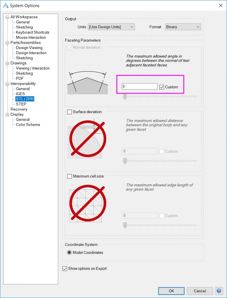
                        System Options -> Interoperability -> STL/ZPR , set surface deviation value to (say) 5 degrees. You may need to experiment a bit.

                        All 3 regions give different ways to control 'smoothness' of the STL output – my first suggestion should get you started. See image.

                        stl param2.jpg

                        #379014
                        Neil Wyatt
                        Moderator
                          @neilwyatt
                          Posted by Paul Abrams on 03/11/2018 16:18:15:

                          re Alibre

                          I'm a beginner and have successfully produced the drawing in issue 274. On completion and exporting it as an STL file for printing with Cura. I find on opening in Cura, the drawing is reproduced as SQUARE!!

                          What should I have done or done wrong?

                          Paul

                          Hello Paul

                          I don't know!

                          I've accepted the defaults in the dialogue David has highlighted and all my 3D prints have come out fine!

                          Neil

                          #379056
                          Neil Wyatt
                          Moderator
                            @neilwyatt

                            You can switch the 3D view between perspective and orthographic, but then I had a shock when this part was rendered as getting bigger as it went 'into' the screen!

                            I checked and the setting is orthographic too!

                            optical illusion.jpg

                            It's actually an optical illusion! Calipers on the screen reveal the panel is drawn the same length at each end, despite appearances.

                            This does show an interesting possibility of 3D printing. I've printed a load of two-part shells for 30-amp connectors to clip into the panel, then I realised that I could print holders directly into the panel (like for the dual USB connector). I will either glue them in or add a simple clip to stop them lifting out.

                            Neil

                            #379073
                            Mark Rand
                            Participant
                              @markrand96270

                              MEW and ME arrived in the post yesterday. Downloaded AA after tea time and spent four hours playing. Did the MEW exercise, then had a go at the milling machine raising block I'm still making.

                              It's a bit frustrating that the included help includes Alibre Design features that aren't there on Atom.

                              Need to find some examples of how to use the assembly tools to orient and position parts, dragging things around in 3D is obviously not the way it should be done!

                              #379088
                              Dennis
                              Participant
                                @dennis66942

                                Hi all,i have tried to draw a simple 2D drawing and find the grid box is missing and no snap commands.also cannot save to cut 2d soft ware to use on mach 3 is this not possible.

                                #379092
                                Stuart Bridger
                                Participant
                                  @stuartbridger82290

                                  Thanks to MEW for giving me the opportunity and incentive to learn 3D CAD. I have run through the first tutorial without issue. Trying get a bit more advanced, I find that I am really struggling with constraints. I must be missing something obvious as sometimes I can't get an item fully defined and have no idea why. It would be really useful to be able to display the properties of an object, to understand what is missing?

                                  For example I am trying to model a flywheel and am trying to position holes to define the spokes. The diagram I am using as a reference specifies a PCD and a horizontal offset from the centre axis. I have a guide circle for the PCD and a horizontal guide line. It looks like an intersection constraint should do the job, but I can't get it to work. Somehow the hole circle is constrained to the PCD line, but I don't know how!

                                  Anay tips would be appreciated, will this be covered in future article?

                                  Stuart

                                  #379100
                                  JasonB
                                  Moderator
                                    @jasonb

                                    Stuart you need to make sure each part of your construction is defined so

                                    1. When you draw your guide circle enter it's diameter.

                                    2. Next as you move the cursor towards the guide circle watch it change then draw your circle, this will place it's ctr point on the guide circle and also give the hole a diameter

                                    3. Your hole is free to move about anywhere on that guide circle so you need to set that position, select dimension, click the ctr of the flywheel and then the ctr of the hole and enter zero when the dim lines are for a horizontal dimension.

                                    4. Now select circular pattern to place the other holes.

                                    Myself I would not use a guide circle just place a hole along the horizontal axis and set its length from the flywheel ctr as half the PCD.

                                    #379101
                                    JasonB
                                    Moderator
                                      @jasonb

                                      Dennis Grid and snap to grid can be turned on and off but mine is not the same as Atom so David or Neil will have to answer though personally I never use snap and neither does David.

                                      Draw the part as a sketch then extrude it even if it is only 1mm thickness and then save. Now create a drawing of the saved part and use that to produce a DWG or DXF 2D drawing


                                      EDIT

                                      4th or 5th page of this tutorial shows where grid and snap can be activated


                                      Edited By JasonB on 04/11/2018 13:57:23

                                      Edited By JasonB on 04/11/2018 13:57:51

                                      #379102
                                      JasonB
                                      Moderator
                                        @jasonb

                                        Mark, if you click "Alibre Atom3D" at the top of this thread by the logo you can download the boring head parts and then go here to download the assemble which will let you see how it was put together

                                        #379119
                                        David Jupp
                                        Participant
                                          @davidjupp51506

                                          Mark – if you want to move on to assemblies ahead of the tutorial, take a look at this group of videos. They do show Alibre Design, but the basic principles apply equally to Atom3D.

                                          #379141
                                          Mark Rand
                                          Participant
                                            @markrand96270

                                            Jason and David. Thank you both very much. This'll keep me occupied for a while tonight (and through the dark winter nights…).


                                            I'd like to grow beyond the Visio that I've been using for 2D and IT related stuff since the Visio company was formed and feel the need to build up some new 'mental muscle memory'.


                                            I can see it costing me some money next year!

                                            Edited By Mark Rand on 04/11/2018 16:57:48

                                            #379146
                                            Les Brown
                                            Participant
                                              @lesbrown65384

                                              New to this link. Very interested to learn about this package. BUT, I am a Mac Book Pro user. Is there a version that works on a Mac. I am sure a lot of your reader are Mac users.

                                              #379151
                                              Neil Wyatt
                                              Moderator
                                                @neilwyatt

                                                Sorry Les,

                                                The problem is that most packages are written for just one operating system.

                                                Neil

                                                #379152
                                                Neil Wyatt
                                                Moderator
                                                  @neilwyatt

                                                  To switch on/adjust the grid:

                                                  File … system options (near bottom right)

                                                  In the options box choose Drawings–Sketching

                                                  Display, snap and sizing for the grid are among the options.

                                                  You can also change them for Parts/Assemblies.

                                                  Hope that helps,

                                                  Neil

                                                  #379461
                                                  Paul Abrams
                                                  Participant
                                                    @paulabrams18342
                                                    Posted by Neil Wyatt on 04/11/2018 17:38:42:

                                                    To switch on/adjust the grid:

                                                    File … system options (near bottom right)

                                                    In the options box choose Drawings–Sketching

                                                    Display, snap and sizing for the grid are among the options.

                                                    You can also change them for Parts/Assemblies.

                                                    Hope that helps,

                                                    Neil

                                                    I have tried all as above – ticking and unticking – 1" and 0.5" But my grid stays at 25". I am trying to work through the 'Alibre Design Exercise Manual' and having great difficulty. At the moment I'm using Direct Ordinate Entry but am having difficulty remembering the existing sizes!

                                                    The answer re conversion to an STL file works fine – Thanks

                                                    #379472
                                                    Neil Wyatt
                                                    Moderator
                                                      @neilwyatt
                                                      Posted by Paul Abrams on 06/11/2018 17:15:45:

                                                      I have tried all as above – ticking and unticking – 1" and 0.5" But my grid stays at 25". I am trying to work through the 'Alibre Design Exercise Manual' and having great difficulty. At the moment I'm using Direct Ordinate Entry but am having difficulty remembering the existing sizes!

                                                      The answer re conversion to an STL file works fine – Thanks

                                                      Hi Paul,

                                                      My brief experience shows it's best to ignore the grid, place your main block using dimensions from the centre point, and then place all the other sketches by reference to that main block or each other.

                                                      The best approach is to make dimensions follow from each other rather than trying to dimension everything. If you lay out four circles in a square in a sketch you will notice that once the first circle is dimensioned and placed dotted red guidelines appear when other circles are aligned with it, also new circles will 'tend' towards the same size once they are close.

                                                      Once you have placed a figure in a sketch. It's easy to check the size of a sketch other than what you are editing with a temporary dimension (which will show as a driven dimension) you can either choose the red cross or just delete it if you don't want it to be permanent.

                                                    Viewing 25 posts - 76 through 100 (of 841 total)
                                                    • Please log in to reply to this topic. Registering is free and easy using the links on the menu at the top of this page.

                                                    Advert

                                                    Latest Replies

                                                    Viewing 25 topics - 1 through 25 (of 25 total)
                                                    Viewing 25 topics - 1 through 25 (of 25 total)

                                                    View full reply list.

                                                    Advert

                                                    Newsletter Sign-up