Learning CAD with Alibre Atom3D

Advert

Learning CAD with Alibre Atom3D

Home Forums Model Engineer & Workshop Learning CAD with Alibre Atom3D

Viewing 25 posts - 426 through 450 (of 841 total)
  • Author
    Posts
  • #390492
    Tomk
    Participant
      @tomk39956
      Posted by TomK on 10/01/2019 23:18:22:

      Hello Been learning Alibre Atom3D. have run into a problem with creating a hole in a cylinder at an angle.

      Can anyone show me how to put a hole half way along a tapered cylinder at an angle of 25 degrees to the axis of the cylinder to a depth of half the cylinder diameter..

      Cylinder is 0.5" dia at larger end an 0.25 " dia at small end.

      Thanks

      Tom

      Hi

      Thanks to all that have replied to my question. The information supplied has answered my question.

      Thanks

      Tom

      Advert
      #390534
      David George 1
      Participant
        @davidgeorge1

        Hi I have been trying to model a bevel gear but have come to a standstill. I have modelled the outside shape in sketch and then rotated it to make a gear shape then extruded the bore and keyway but I can't work out how to cut the teeth from the blank gear shape.

        David

        #390537
        JasonB
        Moderator
          @jasonb

          David, are you after an exact bevel gear or just something that will look like one on a model?

          #390539
          David George 1
          Participant
            @davidgeorge1

            One that looks like on a model as it is a bought in item from decal.

            David

            #390541
            David Jupp
            Participant
              @davidjupp51506

              For bevel gears take a look at this this thread on the Alibre user forum. I think the part file in post #11 is the easiest to download and play with, but you'll probably need to read earlier posts to understand how to use it.

              I should mention that I am not skilled in the fine detail of such gears, so I can't vouch for the equations used etc. The basic approach to the modelling should give some ideas.

              I have checked that the template does indeed work with the current Atom3D – just open the equation editor and change the Z values, then wait for the model to update.

              EDIT – later in that thread is a version for producing skewed bevel gears.

              Edited By David Jupp on 11/01/2019 14:35:42

              #390547
              JasonB
              Moderator
                @jasonb

                I came up with this while David was typing

                Similar to his post earlier today create a plane to the sloping side of the gear blank

                bevel1.jpg

                Then sketch your gear profile on this, I just did a simple straight sided form for this example

                bevel2.jpg

                Cute extrude this to the inside edge with some draft

                bevel3.jpg

                Then make a circular pattern with the number of teeth you want, I then rounded a few edges to get something a bit more like a gear

                bevel4.jpg

                bevel 5.jpg


                Edited By JasonB on 11/01/2019 14:57:16

                #390552
                Tim Taylor 2
                Participant
                  @timtaylor2
                  Posted by David Jupp on 11/01/2019 08:10:16:

                  Tim, what I assume to be the first plane in your description can perhaps be created more easily – see image.

                  Apologies in advance if I mis-interpreted your method.

                  Nope, I missed using the tangent slope function. We got the same result, but your way is simpler.

                  Thanks,

                  Tim

                  #390561
                  Chris Gill
                  Participant
                    @chrisgill22114

                    After lots of messing around I finally managed to model something I may, one day, try to make.

                    I even got the various items working and it highlighted several small problems in the original design. Thanks for all the expert comments on this thread.

                    I have to admit I do keep hitting frustrating problems – reference lines that don't stay put and may vanish without trace, stack dumps and sketches that were editable before I clicked Save and then become locked in some way. Looking on Alibre's forum it seems even the professionals are having problems.

                    eh cataract.jpg

                    #390599
                    eddie dicker
                    Participant
                      @eddiedicker50763

                      Has anyone had issues with the top menus disappearing when saving?

                      I bought a new graphics card (its a Nvidia gigabyte 1030) as my old one wouldn't run the software at all.

                      I looked the issue up on line and it said the graphics drivers can be an issue; so I downloaded the latest from Nvidia and thought all was good.

                      But I just saved that latest bit of the magazine model and its done it again?

                      #390613
                      Lionel Pullum
                      Participant
                        @lionelpullum53107

                        Hi guys

                        I think I have found a possible bug in AA3D. I'm trying to fillet a cutout made from lines and ellipse segments, but I cannot select the elipse segment, see the attached figure. Fortunately the workaround is fairly simple, just create a circle the same radius as your filet, constrain it to be tangent to the required lines and trim, as shown. However if this is a bug can it be put on the bug list and addressed

                        BTW David, thanks for the info about spline input, I was in the middle of nowhere (Australia is large) and could not access the web

                        fillet workaround.jpg

                        #390614
                        Anonymous
                          Posted by David George 1 on 11/01/2019 13:46:10:

                          Hi I have been trying to model a bevel gear but have come to a standstill…………………..

                          This is how I modelled a bevel gear, although be aware that I use Alibre Expert. First I calculate all the parameters. Then I set up the construction planes and axes to get a plane that represents the outer face of a tooth. Then I draw a cone that represents the root angle cone. The gear is initially drawn as 1DP.

                          root cone.jpg

                          Then a sketch representing the involute function of a single tooth is placed on the plane representing the face angle of the outer edge and adjusted to line up with the root cone. The involute sketch was imported as a DXF gear, the unwanted parts deleted and the DXF exploded to give a sketch consisting of straight lines. All in all a bit of faff:

                          involute sketch.jpg

                          The sketch is then lofted to a single point at the origin to form one tooth:

                          single tooth.jpg

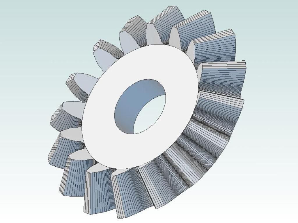
                          There seems to be bug in Alibre here; the loft won't work to a point even though the manual says it will.. I needed to draw a 2 thou square, 7 thou above the origin, and then the loft worked. Note that the outer edge of the tooth isn't a good fit. That's because the sketch was drawn on a plane rather than projected onto the cone that represents the outer surface of the gear. Next is a simple circular pattern for 16 teeth, although it takes a while to compute:

                          all teeth.jpg

                          Finally a nunber of simple revolve cuts tidy up the model so we have a proper gear:

                          complete bevel.jpg

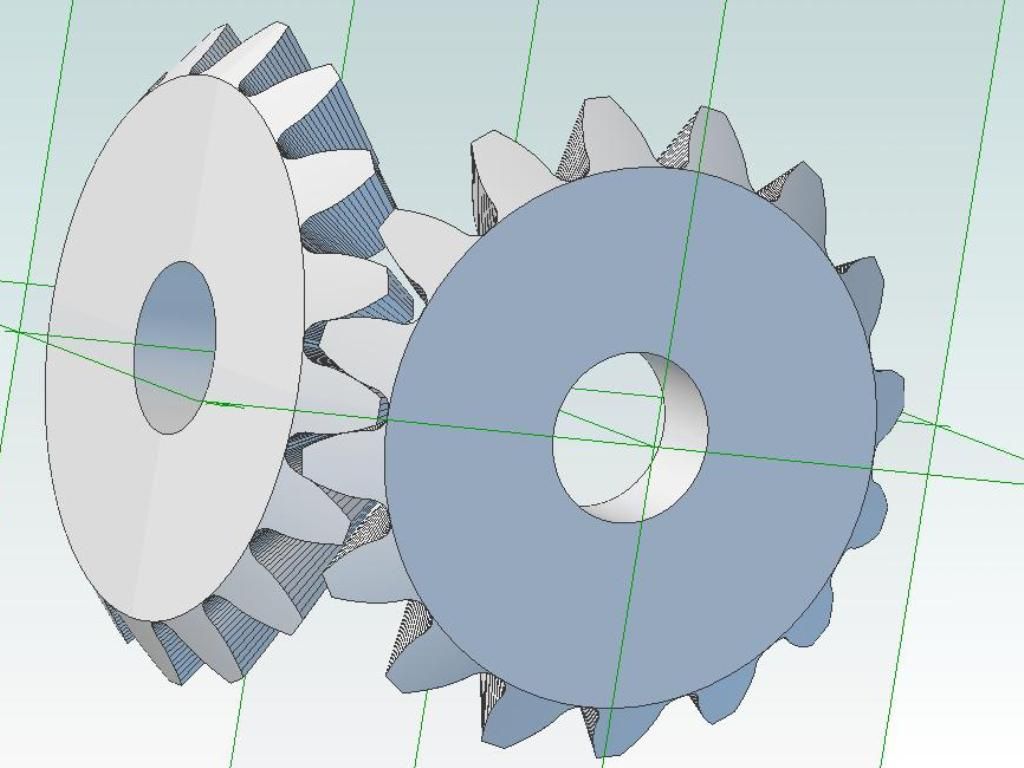
                          An assembly can then be created to visually check meshing:

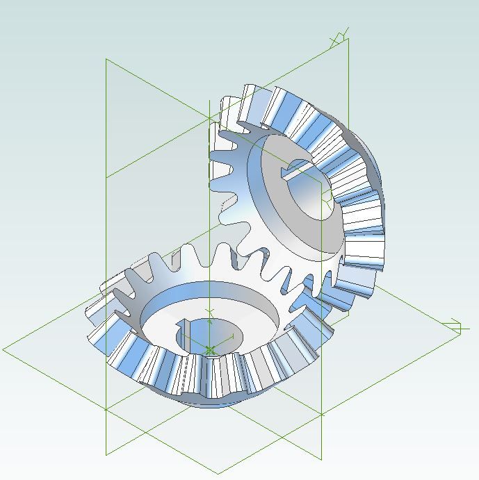
                          assembly.jpg

                          Andrew

                          #390615
                          Anonymous

                            Thought I'd better split the previous post into sections in case I got dumped for rambling on for too long!

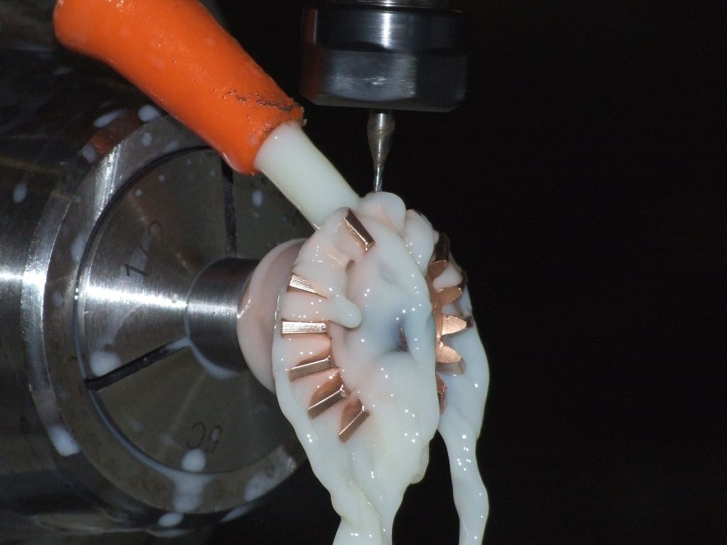
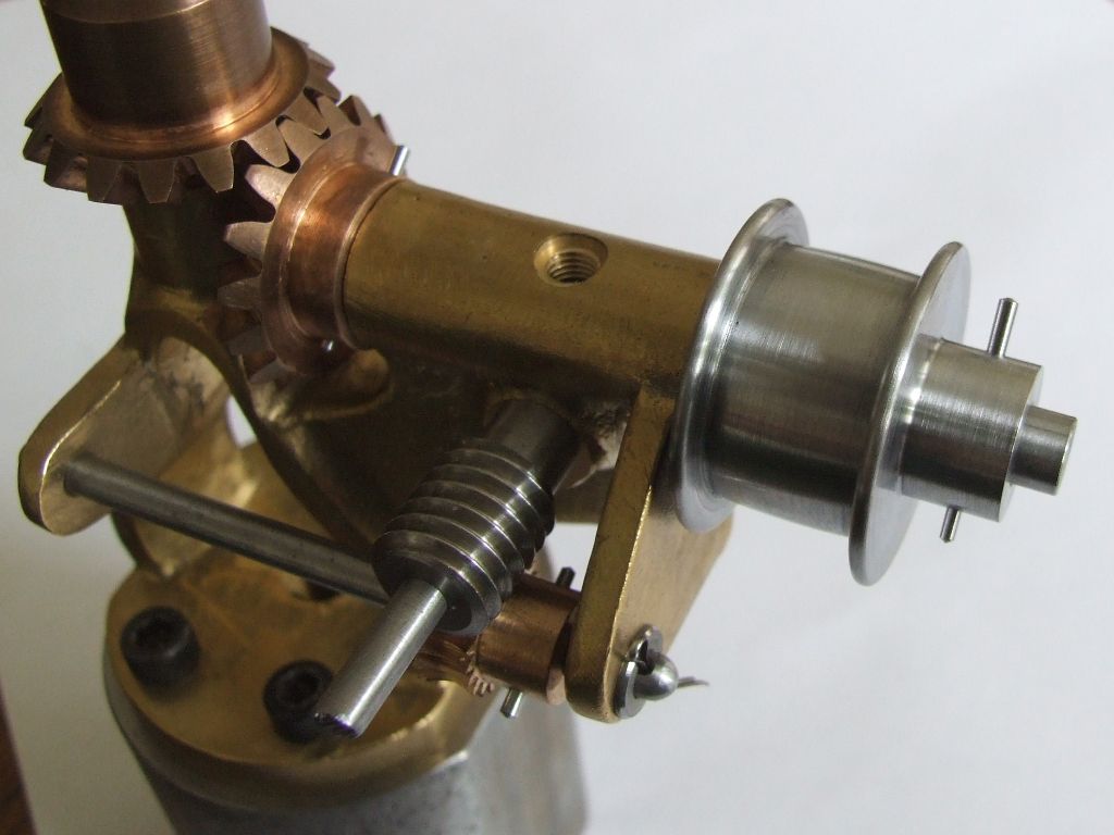
                            Although the model creation is involved I needed it to accurately represent the gear as I would be making real gears from the model. The gears above were created as 1DP; to get the final 16DP gears it's a simple scale by 1/16. All the little errors created in the original modelling usefully get reduced by the scale factor. After some faffing with the CAM program the bevel gear can be machined on a CNC mill, with a 1mm ballnose cutter:

                            governor bevel gear cnc.jpg

                            And the gears fitted on the governor:

                            governor pulley pinned.jpg

                            The meshing is smooth. Some while back at a SCMTEG meeting a member, who is also on the forum, was observed having a detailed look at the gears and turning them to check meshing. He didn't comment to me, so either they were dreadful, or he couldn't find any imperfection to point out. smile

                            Andrew

                            #390617
                            Anonymous
                              Posted by David Jupp on 11/01/2019 14:15:37:

                              For bevel gears take a look at this this thread on the Alibre user forum.

                              Thanks for that David. I'm interested in skew bevel gears, just out of idle curiosity. I'm aware of the work by Kozo and others modelling the gears for logging locomotives. But their pinions have teeth that have considerable lean on them, not at all like the full size gears. I want to have a go at making a set that look like the real thing. I must have a login to the Alibre forum; simply (?) a case of finding out what it is.

                              I started modelling a set of skew gears. A passable version of the gear is fairly simple using a loft to a point on a circle rather than to the centre of the gear:

                              skew bevel gear.jpg

                              But I miserably failed to model a pinion. Skew gears are a complete fudge. As the pinion rotates the gear teeth not only rotate with the pinion but they must also slide along it. So that means the DP must be changing. So the gears can't mesh along a line, but must be at a point. I gather the original gears were rather noisy and prone to wear. On the Alibre forum post it was surmised that the full size originals were mucked about with in wood until they meshed, and then were cast from the wooden patterns. I'd go along with that.

                              Andrew

                              #390648
                              JasonB
                              Moderator
                                @jasonb
                                Posted by Lionel Pullum on 11/01/2019 23:05:01:

                                Hi guys

                                I think I have found a possible bug in AA3D. I'm trying to fillet a cutout made from lines and ellipse segments, but I cannot select the elipse segment, …………………………………..

                                Lionel, ellipses can have a few quirks to them. You may well find it better to leave the corners as they are on your 2D sketch then extrude or cut that sketch. Once you have done that use the fillet tool in part modeling and select the lines of the internal corners you want to fillet and it will pick up all the ones that intersect the ellipse

                                fillet ellipse.jpg

                                fillet ellipse2.jpg


                                Edited By JasonB on 12/01/2019 07:49:32

                                #390651
                                David Jupp
                                Participant
                                  @davidjupp51506
                                  Posted by eddie dicker on 11/01/2019 21:01:44:

                                  Has anyone had issues with the top menus disappearing when saving?

                                  I bought a new graphics card (its a Nvidia gigabyte 1030) as my old one wouldn't run the software at all.

                                  I looked the issue up on line and it said the graphics drivers can be an issue; so I downloaded the latest from Nvidia and thought all was good.

                                  But I just saved that latest bit of the magazine model and its done it again?

                                  Eddie – if the Ribbon gets replaced by a Red X – this is a known issue caused by a Windows update – see this article for explanation and a way to resolve it.

                                  #390679
                                  John Hinkley
                                  Participant
                                    @johnhinkley26699

                                    Having come to the conclusion that my design for a four-cylinder engine will only ever be a virtual construction, I have ditched the water-cooled version in favour of an air-cooled one. This has massively simplified the block and head design and allowed me to progress a little further. Spurred on by the recent discussion in this thread concerning the use of the sweep tool, I have smoothed out the inlet and exhaust ports to follow an angled path from head side face to valve throat. Very satisfying – but it took some figuring out with the new planes and axes to insert. Not helped, I suppose, by my use of angled valves and ports! Keeps the grey matter working, though.

                                    Here's what it looks like at the present stage of development:

                                    Air-cooled engine assembly

                                    John

                                    #390681
                                    SillyOldDuffer
                                    Moderator
                                      @sillyoldduffer
                                      Posted by John Hinkley on 12/01/2019 11:12:36:

                                      Having come to the conclusion that my design for a four-cylinder engine will only ever be a virtual construction, I have ditched the water-cooled version in favour of an air-cooled one. This has massively simplified the block and head design and allowed me to progress a little further. Spurred on by the recent discussion in this thread concerning the use of the sweep tool, I have smoothed out the inlet and exhaust ports to follow an angled path from head side face to valve throat. Very satisfying – but it took some figuring out with the new planes and axes to insert. Not helped, I suppose, by my use of angled valves and ports! Keeps the grey matter working, though.

                                      Here's what it looks like at the present stage of development:

                                      Air-cooled engine assembly

                                      John

                                      I'm impressed! smiley

                                      Dave

                                      #390798
                                      Lionel Pullum
                                      Participant
                                        @lionelpullum53107

                                        Thanks Jason

                                        Thats obviously a mu ch better workaround for the ellipse issue

                                        #390799
                                        Tim Taylor 2
                                        Participant
                                          @timtaylor2

                                          Awesome John!

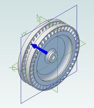
                                          I think I'm starting to get a feel for the A3d software. The picture below is a single row wheel for a steam turbine – I did it as a learning tool…the actual scale model turbine I am designing will have a 2 row wheel with reversing sector.

                                          The most tedious part was figuring out the bucket design – it starts out with an extruded rectangular block, which is then shaped to profile by a couple of extrude cuts. The circular pattern was used to create the buckets in two steps – first the rectangular blocks, then the extrude cuts using the same parameters. I did it this way because as far as I can tell, the circular pattern will only work on one feature at a time.

                                          The wheel body was a couple of extrudes and very straightforward.

                                          The rim was created separately and then projected to a sketch, which was copied and positioned on the wheel using the paste stamp function, then extruded to width.

                                          I did this early in the week, and in retrospect it looks like there are a couple of steps that could have been combined – will play with that when I get a chance.

                                          Tim

                                          turbwhl.jpg

                                          #390806
                                          Tim Taylor 2
                                          Participant
                                            @timtaylor2

                                            I was able to consolidate some operations – this is the 2 row Curtis stage wheel design with a dished rotor……….

                                            2rowturbwhl.jpg

                                            #390820
                                            Neil Wyatt
                                            Moderator
                                              @neilwyatt

                                              Hmmm… Nylon 6 can stand temperatures up to 150C, which is steam at 50psi.

                                              How about 3D printed turbine Blades for a low-pressure steam turbine, say 30-40psi?

                                              Neil

                                              #390823
                                              David Jupp
                                              Participant
                                                @davidjupp51506

                                                Tim – the feature pattern tool should be able to cope with multiple features in a single pattern.

                                                #390842
                                                Keith Rogers 2
                                                Participant
                                                  @keithrogers2

                                                  Neil, as Nylon 6 is hygroscopic would that really work as a steam turbine? I guess it would be fine if run on air though.

                                                  Keith.

                                                  Edited By Keith Rogers 2 on 13/01/2019 11:54:52

                                                  #390857
                                                  Neil Wyatt
                                                  Moderator
                                                    @neilwyatt
                                                    Posted by Keith Rogers 2 on 13/01/2019 11:54:08:

                                                    Neil, as Nylon 6 is hygroscopic would that really work as a steam turbine? I guess it would be fine if run on air though.

                                                    Keith.

                                                    Edited By Keith Rogers 2 on 13/01/2019 11:54:52

                                                    Should be fine as long as allowance is made for slight expansion about 1.6% at maximum water content. You could get around this by running the edge of the turbine in a groove rather then just up against the wall of a tube.

                                                    It would only be meant as a demonstration, not a hard-working turbine.

                                                    Neil

                                                    #390858
                                                    Nige
                                                    Participant
                                                      @nige81730

                                                      Im trying to find an 'Undo' button and failing miserably Any help please guys.

                                                    Viewing 25 posts - 426 through 450 (of 841 total)
                                                    • Please log in to reply to this topic. Registering is free and easy using the links on the menu at the top of this page.

                                                    Advert

                                                    Latest Replies

                                                    Viewing 25 topics - 1 through 25 (of 25 total)
                                                    Viewing 25 topics - 1 through 25 (of 25 total)

                                                    View full reply list.

                                                    Advert

                                                    Newsletter Sign-up