Learning CAD with Alibre Atom3D

Advert

Learning CAD with Alibre Atom3D

Home Forums Model Engineer & Workshop Learning CAD with Alibre Atom3D

Viewing 25 posts - 351 through 375 (of 841 total)
  • Author
    Posts
  • #385653
    John Barber 5
    Participant
      @johnbarber5

      Thanks, both.

      Advert
      #385661
      Neil Wyatt
      Moderator
        @neilwyatt
        Posted by John Harding on 12/12/2018 01:36:13:

        After each attempt to change the units, they reverted to inches. This morning when I opened the program I found it had reset to metric.

        David, I have noted your instructions for future use.

        thank you both

        You need to restart the program if you change the default settings.

        Neil

        #386561
        Neil Wyatt
        Moderator
          @neilwyatt

          I found this unbelievable vehicle today after getting lost down a Wikipedia Wormhole (I started with Karman Limit and went via V2 and a whole load of strange WW2 German weapons). It turns out it is real and there is one in a Russian tank museum, although with only 5mm plate it's probably not meant as an attack vehicle, and it's only 1.5 metres in diameter.

          I will be 3D printing one of these!

          http://www.tanks-encyclopedia.com/ww2-german-prototypes/kugelpanzer/

          Took about an hour to draw this up, hardest bit was getting the tail to look about right playing with fillets and dimensions. It's an assembly of 3 parts, body and 2 wheels.

          kugelpanzer.jpg

          #386796
          John Barber 5
          Participant
            @johnbarber5

            Fascinating. The wheels remind me of the Shepherd ball castor.

            #387046
            John Hinkley
            Participant
              @johnhinkley26699

              Made some more progress with my engine design after a short break to let my brain cool down. It's by no means finished but it's coming on slowly and I'm getting in lots of practice with "inserting new planes".

              Cylinder head

              There will be cast iron valve seats shrunk into the head – that's why the valve locations look a bit big.

              Anyone know why I can't re-size the photos in a post anymore. Are they too big?

              John

              #387061
              Neil Wyatt
              Moderator
                @neilwyatt

                Album images are resized to 1024 pixels in the longest dimension and automatically adjusted for display, usually to 512 across.

                Neil

                #387062
                John Hinkley
                Participant
                  @johnhinkley26699

                  Thanks for the information, Neil.

                  John

                  #387177
                  Andrew Evans
                  Participant
                    @andrewevans67134

                    I am trying to model pipework with bends and twists (not always at right angles). It seems like I should be using the 3D sketching feature and then Sweep but 3D sketching is greyed out – is it available in Atom?

                    Thanks in advance. Andy

                    #387205
                    JasonB
                    Moderator
                      @jasonb

                      Not sure if Atom has all the features shown but this may help

                      #387215
                      David Jupp
                      Participant
                        @davidjupp51506

                        3D sketching isn't available in Atom3D – the button was accidentally left visible. Sorry.

                        There are ways this can be worked around, but they become quite complex for anything beyond fairly simple geometry.

                        #387221
                        Andrew Evans
                        Participant
                          @andrewevans67134

                          Thanks for getting back. My plan then is to create planes at different angles to X, Y,Z and sketch circles then join them with the sweep tool. What would be the best way to create new planes at the right angles? Thanks in advance

                          #387309
                          David Jupp
                          Participant
                            @davidjupp51506

                            You can use edges of solids as sweep paths (then hide or suppress these 'construction solids afterwards' ) – you can't join multiple 2D sketches to create a 3D path.

                            Try any method out with a minimal example, so that you don't waste lots of effort on something that won't work.

                            Edited By David Jupp on 23/12/2018 16:48:24

                            #387326
                            Neil Wyatt
                            Moderator
                              @neilwyatt

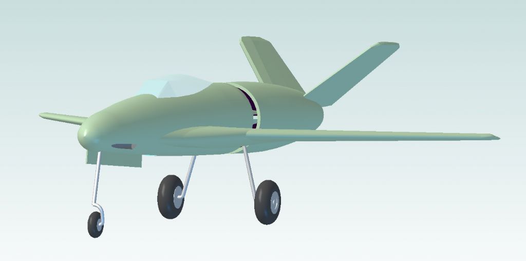
                              Be aware when doing a sweep you have to be very careful that the radius of any bends is greater than the width of the part as if it 'intersects itself' the extrude will fail.

                              The lower section of this nose 'oleo' was done as a sweep after much cursing to to get the path right.

                              p1110 again.jpg

                              #388104
                              John Harding
                              Participant
                                @johnharding75458

                                Reference point Fig.25 p23 (MEW275) With XY plane only one set green lines visible, scrolling round does not pick up grey lines.

                                YZ and ZX planes both display two sets of green lines. (and SWMBO agrees with that)

                                This after clicking on 'Show ref drwg'. Following previous advice I tried "Resetting" Which also meant resetting the units. (thank you Neil for your note) Presumable the arrows are for guidance?

                                each attempt has been with a redrawn base part and obtained 'Alignments.'

                                JH

                                #388111
                                David Jupp
                                Participant
                                  @davidjupp51506

                                  Perhaps your XY planes are already coincident, so don't show up separately…. try dragging the part 'up' and away from the assembly XY plane.

                                  The arrows on fig 25 show the 'direction' of the selected plane. Planes have a direction – an align constraint of 2 plains sets the directions to be common, whereas a mate constraint sets directions to be opposed.

                                  #388153
                                  Tim Taylor 2
                                  Participant
                                    @timtaylor2

                                    Greetings to all!

                                    I am brand new to this forum, but have been using Cubify Invent for several years to design 3D printed fixturing for laser applications. After playing with the eval version for a week or so, I recently upgraded to Alibre Atom3D.

                                    Atom3D is different enough that there has been somewhat of a learning curve, but I'm getting there. Most of the tutorials I've found online were created for Design and reference some features that are not included in A3D, but for the most part. I've found some good information here that has helped.

                                    I just completed my first assembly, which is a rotating adapter for my fly tying vise. I don't remember if it was mentioned previously in this thread, but even though A3D is very versatile in aligning parts, drawing the part in the axis it will be in relative to the other parts of the assembly makes it a lot easier.

                                    Eventually I will be using it for the design of a scale model steam turbine that I want to design and build.

                                    Tim

                                    #388176
                                    Chris Gill
                                    Participant
                                      @chrisgill22114

                                      Hi all

                                      I've only just installed A3D but I've made it through the on-line tutorial (that 100-page PDF) and the first two parts of the MEW series. In part 3 I keep hitting a problem.

                                      After creating two circles and three lines I created two tangent constraints and a dimension followed by trimming the excess off the lines. That leaves me at figure 7 but when I try to deactivate the sketch or extrude it, I get an error saying there are open loops. Selecting the "open loop" in the list of errors highlights the intersetions between the horizontal lines and the outer circle. I don't know if it matters but the tolerance is shown as 0.01mm.

                                      So far I've tried three times without success. Does anyone know what I'm doind wrong?

                                      Thanks

                                      Chris

                                      #388218
                                      David Jupp
                                      Participant
                                        @davidjupp51506

                                        Chris – assuming the draft of the article I'm looking at has the same figure numbers as the published one, figure 7 isn't ready for extrusion. There is a final trimming stage of the outer circle (to reach figure 8) before closing the sketch.

                                        The tolerance value is for the 'Heal' option, that is used for automatically mending small gaps in sketches. I doubt it is relevant to your current problem.

                                        #388232
                                        JasonB
                                        Moderator
                                          @jasonb

                                          Text reads the same in the mag, the black half the outer circle in fig 7 needs to be trimmed so you just have the elongated "D" shape with a hole.

                                          #388318
                                          mick
                                          Participant
                                            @mick65121

                                            I like to think that I'm starting to get to grips with the basics as I tend to spend at least a half an hour a night generating complex models that I wouldn't have the first idea how to set about machining. I realise the monthly tutorials are designed to show different modelling methods and so I've followed this month's tutorial to produce the clamp block occording to the instructions althought it would be easy to produce just using the sketching tools. When I try to trim the obsolete construction lines in fig5 I get a warning saying 'to trim the constraint lines will unlock the constraints' and a yes or no option. If I click yes then I can't extrude the block, if I click no then I can't trim the excess construction lines. Sorry about the spelling but the spell checker seems to have taken a Christmas break!

                                            #388321
                                            Chris Gill
                                            Participant
                                              @chrisgill22114

                                              David, Jason – many thanks. I read that lot three times and still missed it! sad And now for my next screw-up …

                                              #388331
                                              David Jupp
                                              Participant
                                                @davidjupp51506

                                                Mick – can you post an image of what stage you can reach with the sketch? I suspect that you maybe haven't trimmed enough pieces. I presume the warning popped up at your first attempt to use trim? if so there is extra trimming required afterwards. Your sketch should look like Figure 8 before you try to extrude.

                                                #388416
                                                Tim Taylor 2
                                                Participant
                                                  @timtaylor2
                                                  Posted by Ken Strauss on 18/11/2018 15:46:24:

                                                  So far so good but has anyone tried Atom3d in conjunction with a CAM package? There doesn't seem to be a .dxf export and .stl is not really appropriate. The Mecsoft CAM costs from than Atom3d!

                                                  I have both SheetCam and LazyCam and have used A3D DXF export for some simple parts just to test it – works OK so far.

                                                  Tim

                                                  #388819
                                                  Andrew Evans
                                                  Participant
                                                    @andrewevans67134

                                                    An update on my progress with modelling the pipes in multiple planes. I have got there in the end and am pleased with the results although it has taken a while. Thanks for the advice.

                                                    The sweep tool makes sense when you realise how it works, you just have to get your head around creating planes at the correct angles and locations and then sketching the sweep path on those planes. Some of what I wanted to do would have been easier with the 3D sketch function which is not available in this version.

                                                    In terms of using David Jupp's suggestion of creating solids purely as basis for paths and edges of other solids and then deleting or suppressing them – that makes total sense and is a great idea but I found does not quite work in practice. Once you delete or suppress a solid anything based on it then becomes invalid in the model (the software needs a feature to allow this in some way – suppressing a solid should just hide it surely but the way it works is that it has the same effect as deleting it but you can undelete at a later point). The way i got around this was to cut away at the 'guide solid' so it only existed within the existing solid and so is not visible – if that makes any sense – but it was a lot of work.

                                                    I did have a few issues, which I consider bugs in the software. e.g. the fillet tool stopped working and gave a popup error each time I used it. It was cured by closing all instances of Alibre and restarting.

                                                    Some things I found could be simpler. I was basing my model on an original drawing which has dimensions on the projected front view, side view etc – e.g. overall height of the part as viewed from the front. I wanted to check these dimensions in Alibre matched to ensure I had modelled it correctly. The only way i found to do that was to create the drawings from the finished model and then create dimensions in the drawing. If I made a mistake I had to go back to the model, fix it and then regenerate the drawing and remeasure. Maybe there is a simple way to get dimensions in the model itself such as overall height in the XY plane etc?

                                                    Overall I really like Alibre Atom3D and it seems great value for such a powerful package.

                                                    #388831
                                                    David Jupp
                                                    Participant
                                                      @davidjupp51506

                                                      Andrew – there is a measurement tool in the 3D workspace (The Ruler symbol – to the right of the view orientations at top of screen). This will give dimensions between selected features in the 3 principal directions, in addition to the 'shortest straight line'.

                                                      Sorry if my suggestion for guide solids wasn't helpful – if you can tolerate the solid remaining present, use of 'Hide' should work better – though this would require other fiddles with drawings etc.

                                                    Viewing 25 posts - 351 through 375 (of 841 total)
                                                    • Please log in to reply to this topic. Registering is free and easy using the links on the menu at the top of this page.

                                                    Advert

                                                    Latest Replies

                                                    Viewing 25 topics - 1 through 25 (of 25 total)
                                                    Viewing 25 topics - 1 through 25 (of 25 total)

                                                    View full reply list.

                                                    Advert

                                                    Newsletter Sign-up