Learning CAD with Alibre Atom3D

Advert

Learning CAD with Alibre Atom3D

Home Forums Model Engineer & Workshop Learning CAD with Alibre Atom3D

Viewing 25 posts - 326 through 350 (of 841 total)
  • Author
    Posts
  • #384315
    David Jupp
    Participant
      @davidjupp51506

      Paul, If you mean a simple hemi-spherical dome (or similar) – I'd probably just add a fillet of appropriate size to the edge of the cylinder.

      If it need to be hollow I'd make sure to fillet the inside 'corner' before the outside one.

      Sketching a half cross section and revolving it around the axis of the cylinder is another obvious way – but requires a bit more proficiency with the sketch tools.

      If I've mis-understood your requirement, can you post here or PM me an image of roughly what you want to achieve?

      Advert
      #384316
      JasonB
      Moderator
        @jasonb

        The easiest way is to use "Fillet" as that will put a curved fillet into internal corners or round over external ones.

        Select fillet from the bar along the top, then you can either select the end face of the cylinder or it's edge where it meets the side followed by entering the radius which should be half the diameter of the cylinder.

        This is a similar function to the chamfer to the base that was shown in part one of the series, if you want to look at that as a guide.

        #384322
        Neil Wyatt
        Moderator
          @neilwyatt
          Posted by Paul Abrams on 07/12/2018 09:56:12:

          I'm trying to put a dome end onto an air cylinder but cannot find the information in the help files. Can you point me in the right direction. I have been trying to adapt the instructions on page 20 of MEW but getting nowhere!

          A written manual or book on the Atom 3D would be really helpful – I know I'm expecting too much but any ideas please!!

          Draw two circles to create the right thickness, use two lines and trim to make a 90-degree segment of the right thickness, then rotate it into a hemisphere.

          Neil

          #384326
          JasonB
          Moderator
            @jasonb
            Posted by Paul Abrams on 07/12/2018 09:56:12:

            A written manual or book on the Atom 3D would be really helpful – I know I'm expecting too much but any ideas please!!

            Paul if you follow this link it will take you to the Atom Tutorial Manual which covers a lot more than the mag articles can. Page 59 shows the end of a solid cylinder being rounded.

            If you want a spout or end fitting to the cylinder then drawing a half section and rotating will be the better option

            #384329
            Paul Abrams
            Participant
              @paulabrams18342

              Hello Jason……….I did originally put a fillet on the edge but needed a more 'bulbous' end to which I can then still fillet the edge afterwards. I didn't want a flat end filleted or a 'rounded end. Doesn't sound as if it's possible?

              I am also having problems with converting to a Cura file (stl). A simple Atom 3D drawing converted ends up in Cura as a 535mb stl file to which it is too big to load or send a copy as an attachment on an email.

              Paul

              #384332
              JasonB
              Moderator
                @jasonb

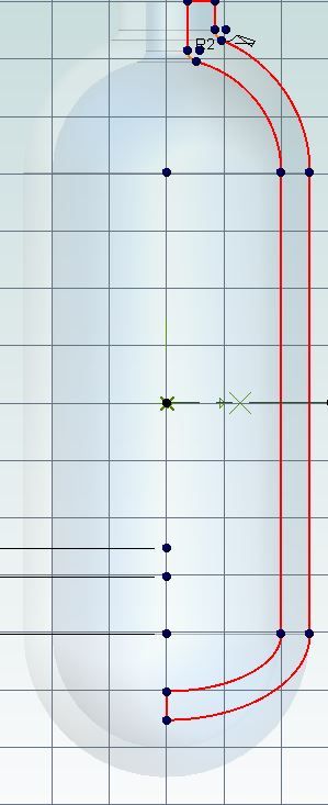
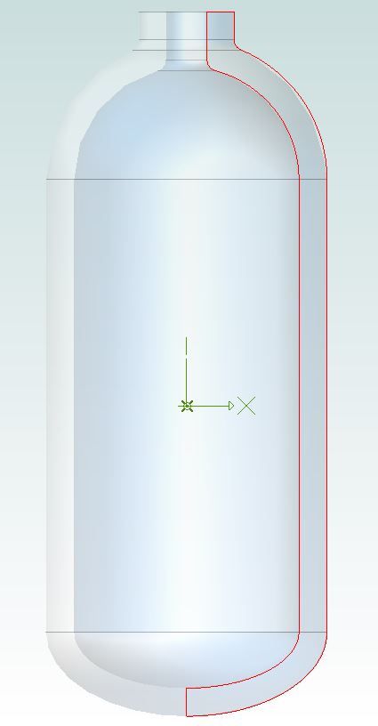
                If you want something other than a pure radius than it will be best to draw a section and then revolve it, something like this where I use circles at the top and elipses at the bottom.

                cylinder2.jpg

                cylinder3.jpg

                #384338
                David Jupp
                Participant
                  @davidjupp51506

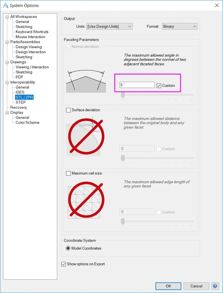
                  STL output from Atom – make sure that Binary rather than ASCII is set as Format the Interoperability options for STL/ZPR (binary file will be a lot smaller). You can additionally adjust any of the 3 Faceting Parameters to balance file size with 'smoothness' of model. You'll probably get away with adjusting Normal Deviation – you have to check the Custom Box to change from the default value.

                  stl param2.jpg

                  #384340
                  David Jupp
                  Participant
                    @davidjupp51506

                    If your cylinder has uniform thickness, you can simplify the construction by only sketching the external (half) profile. Revolve that to create a solid, then used Shell command to 'hollow out' the solid and put a hole in the neck.

                    You could make the hole as a separate operation.

                    #384370
                    Paul Abrams
                    Participant
                      @paulabrams18342

                      Thanks Jason and Neil……I think it is two steps forward and one back. I've changed the ASC11 to Binary & the 5% works OK on the faceting. That problem solved.

                      I had already gone through the Atom Tutorial Manual (inches not in mm) but it is a step by step guide and no way to find individual queries. The 'HELP' button doesn't allow for finding things easy either.

                      Your drawing of the bottle shape comes from a different starting point than the way I was approaching the problem. I was doing it step by step as per the MEW and Manual instructions. This Atom 3D programme looks very promising and hopefully the MEW course will go further than the four months envisaged. Unfortunately age is not on my side and I need to know it all now!!

                      Paul

                      #384435
                      Nick Hughes
                      Participant
                        @nickhughes97026

                        Paul,

                        Check your "Inbox" I have sent you a message that might interest you.

                        Nick.

                        #384840
                        John Barber 5
                        Participant
                          @johnbarber5

                          Hi David and Jason,

                          I have a couple of questions related to the second MEW article:

                          1. I assume he only used 'revolve cut' to teach us the technique, as it would have been easier to use extrude with a draft angle, as we did for the tapered hole in part 1.

                          2. At the assembly stage, is it not possible in Alibre to 'mate' the two conical surfaces, rather than just align them? That would better reflect the physical reality of the situation.

                          Thanks,

                          John

                          #384848
                          David Jupp
                          Participant
                            @davidjupp51506

                            John,

                            1. Yes Rob was trying to show a range of modelling methods. There are actually more ways the taper could have been added (chamfer tool for one).

                            2. Mate works for planar surfaces. Cylindrical or Conical surfaces have their axis picked up, which can be used for Align, but doesn't make any sense for Mate. Rob uses the align of the end face with underside of base to achieve final position.

                            Alibre Design does offer additional constraint types – but even they don't help much in this example.

                            Edited By David Jupp on 10/12/2018 11:34:08

                            #384901
                            John Barber 5
                            Participant
                              @johnbarber5
                              Posted by David Jupp on 10/12/2018 11:26:17:

                              There are actually more ways the taper could have been added (chamfer tool for one).

                              Yes, I've just discovered you can define a chamfer by a length and an angle. That would be a very good method.

                              #384986
                              John Harding
                              Participant
                                @johnharding75458

                                Directions please for changing from inches to metric.

                                John

                                #384993
                                JasonB
                                Moderator
                                  @jasonb

                                  Follow this tutorial to see how to change units and how many decimal places etc.

                                  If you have it set to metric you can still enter an imperial size if you want, just put " at theend of any size you enter and it will drawing to the inch size but display in metric. I tend to use it more the other way round with say a metric tapping hole on an imperial drawing.

                                  #385012
                                  John Harding
                                  Participant
                                    @johnharding75458

                                    Thank you Jason, the tutorial is easy to follow but at stage 7 the APPLY box is just visible half off the screen.

                                    Clicking on that un does the previous stage 6 so no change ( I am working on lap top with 14" screen)

                                    John

                                    #385038
                                    JasonB
                                    Moderator
                                      @jasonb

                                      I may have to defer to David as my version is not quite the same but I just click apply and then close.

                                      This shows me opening a new part and drawing a circle while set to imperial, I then change to metric, apply and close. The next new part I start will still be imperial, had I ticked to save as default then subsequent new parts will all be metric.

                                      J

                                      Edited By JasonB on 11/12/2018 12:11:42

                                      #385079
                                      David Jupp
                                      Participant
                                        @davidjupp51506

                                        John – Apply should do just that. A couple of things to try – first try using TAB to move out of last altered field.

                                        If that doesn't help, it may be that your user profile is damaged – there is a link to re-set this on the Utilities tab of the Home Window. Re-setting User Profile can fix various oddities with the user interface.

                                        #385208
                                        John Harding
                                        Participant
                                          @johnharding75458

                                          After each attempt to change the units, they reverted to inches. This morning when I opened the program I found it had reset to metric.

                                          David, I have noted your instructions for future use.

                                          thank you both

                                          #385497
                                          JasonB
                                          Moderator
                                            @jasonb

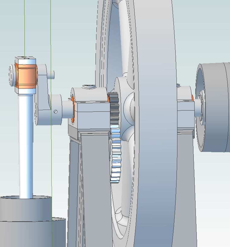
                                            When using gears in an assembly is there a way to have them mesh and revolve as you turn one part? I'm currently drawing up an IC engine and it would be nice if the timing gears would actuate the eccentric that operates the exhaust valve.

                                            Also can a ratchet wheel be assembled so that the pawl will move it one notch at a time?

                                            gear mesh.jpg

                                            Edited By JasonB on 13/12/2018 17:20:25

                                            #385503
                                            David Jupp
                                            Participant
                                              @davidjupp51506

                                              Jason,

                                              Not simply, no. There might be some 'dodges' possible to do some of this using hidden parts, but nothing simple.

                                              I'm struggling to remember if I've seen a dodge for reduction gearing. Ratchet, I'm sure I haven't seen.

                                              Some of the guys over on the Alibre forum come up with some sneaky methods – could be worth posing the question there.

                                              #385507
                                              JasonB
                                              Moderator
                                                @jasonb

                                                Thanks David.

                                                #385608
                                                John Barber 5
                                                Participant
                                                  @johnbarber5

                                                  If I do an Extrude Cut and the sketch goes outside the material, I am left with some red lines in the Part display. What are they for, please, and can I switch them off?

                                                  #385611
                                                  JasonB
                                                  Moderator
                                                    @jasonb

                                                    They show the outline of the sketch that was used for the cut, should be able to switch off in system options as I don't think Atom has a tab but worth clicking the Viewing & analysis tab first to see if there is a toggle

                                                    #385615
                                                    David Jupp
                                                    Participant
                                                      @davidjupp51506

                                                      John, probably the outline of your sketch visible – you can toggle off sketch visibility for the display. Check the Viewing Options portion of the Viewing & Analysis tab of the Ribbon. Ctrl+Shift+K will also toggle sketch visibility.

                                                      Edited By David Jupp on 14/12/2018 11:08:47

                                                    Viewing 25 posts - 326 through 350 (of 841 total)
                                                    • Please log in to reply to this topic. Registering is free and easy using the links on the menu at the top of this page.

                                                    Advert

                                                    Latest Replies

                                                    Viewing 25 topics - 1 through 25 (of 25 total)
                                                    Viewing 25 topics - 1 through 25 (of 25 total)

                                                    View full reply list.

                                                    Advert

                                                    Newsletter Sign-up