Learning CAD with Alibre Atom3D

Advert

Learning CAD with Alibre Atom3D

Home Forums Model Engineer & Workshop Learning CAD with Alibre Atom3D

Viewing 25 posts - 226 through 250 (of 841 total)
  • Author
    Posts
  • #382100
    David Jupp
    Participant
      @davidjupp51506

      JohnF – though not officially supported on Mac, there are people out there successfully running Alibre software on (Intel based) Macs using Parallels (for example) – obviously you need a Windows licence.

      Advert
      #382118
      David Jupp
      Participant
        @davidjupp51506

        Duncan,

        Centre of Mass – Click on 'Viewing and Analysis' tab – click 'Physical Properties' – that will give co-ordiantes of the Centre of Mass. If you have defined the material, it'll tell you part weight too.

        #382148
        duncan webster 1
        Participant
          @duncanwebster1

          David,
          If you have defined the material...…..HOW I can't find a way. I've found the calculation bit.
          You have to import DXF into the 2D drawing workspace….. you might see some icons that you don't have access to……. I can't find any icons referring to import. Google is singularly unhelpful, just refers to the full version
          I've worked through part 2. Keep it coming! I'm actually getting faster, or perhaps less glacial

          #382154
          Neil Wyatt
          Moderator
            @neilwyatt

            Wow, Just found the 'centre of mass' calcs, handy if I ever design a ship…

            Also 'create drawing from part'!

            Neil

            #382167
            duncan webster 1
            Participant
              @duncanwebster1

              And another question. Having made an assembly of 2 parts, if I then modify one of the parts in the part drawing, how do I make the assembly update itself? Again the stuff on Google refers to icons/menus I can't find on Atom

              #382181
              JasonB
              Moderator
                @jasonb

                The assembly will update the next time you open it so if you have both open close the assembly.

                To set material click the Atom gem then at the bottom of that drop down click "Properties" and the tab that comes up has the material options.

                #382186
                David Jupp
                Participant
                  @davidjupp51506

                  Duncan – as I mentioned before, where it says Import in the video, use Open. There used to be separate Import and Open options for files – but they really did the same thing, just listing different file types. The 2 were consolidated into the file Open icon.

                  So click Atom2D icon at top left of screen -> click open, or just click Open on the Home Window and choose the DXF file.

                  OR from Windows, right click DXF file, choose 'Open With', then choose Atom3D.

                  #382190
                  John Hinkley
                  Participant
                    @johnhinkley26699

                    At the risk of monopolising this thread and clogging it with photos, I present my attempt at assembling various parts:

                    First trial assembly

                    This is not the first effort – I tried fitting the block and crankshaft together, only to find that I'd made a couple of fundamental dimensional errors in the block design. I thought that I would have to start all over again, but luckily I realised that Atom allows you to make alterations to the sketches, which meant it only took a short while to remedy things. It also reiterated the fact that, with a large and/or complicated drawings, it makes sense to give each sketch an identifying name. It makes finding it subsequently in the explorer that much easier. I learned the hard way!

                    Once I've put the conrods and pistons "in", I'll investigate the motion system.

                    John

                    Still on the foothills of the learning curve!

                    #382191
                    David Jupp
                    Participant
                      @davidjupp51506

                      Updating Assemblies after editing parts – it's just like Jason said a couple of posts above.

                      There are other options that can shortcut this, and give you very powerful capabilities; see this video.

                      'Edit Here' and 'Edit in Separate Window' allow you to alter parts in the assembly whilst the assembly is open and see the results immediately. There some pitfalls to be aware of though.

                      #382195
                      John Hinkley
                      Participant
                        @johnhinkley26699

                        Thanks, David, I'll have a look later.

                        John

                        #382205
                        JasonB
                        Moderator
                          @jasonb
                          Posted by John Hinkley on 25/11/2018 08:38:56:

                          Once I've put the conrods and pistons "in", I'll investigate the motion system.

                          John

                          John, I would suggest making a separate assembly of the Conrod, cap, any bearing shells and wrist pin. You can this bring this assembly into your main one which makes life a bit easier.

                          You may also find it helps to set the crankcase to semi transparent so it is easier to see what is going on.

                          One other general comment for anyone is that if you go back to alter one of the sketches that make up a part do make sure you click on the "generate to last feature" before saving as the part will get saved at the point where that sketch is down the list on the left. You won't loose any subsequent sketches but the actions won't be shown.

                          This can also be taken advantage of by putting all of your cosmetic actions such as fillets, chamfers, visual threads etc at the end so they can be left off when doing assemblies or drawings to make files load faster and keep the drawings clearer.

                          It is also possible to "suppress" any item which removes it from the model but still has it in the list, just right click in the list and click suppress.

                          #382233
                          duncan webster 1
                          Participant
                            @duncanwebster1

                            Thanks David,

                            I can now set properties and update assemblies. I've also opened a dxf of a section through a disc wheel, but I think I'm going to have wait for a future episode to find how to then rotate the shape to form a 3D model. Probably getting a bit in front of myself.

                            Thanks again

                            On a completely different tack, MEW seems to have taken a great leap forwards in the last few issues. I was thinking of stopping my subscription, but the last few have changed my mind.

                            #382241
                            John Hinkley
                            Participant
                              @johnhinkley26699

                              Jason, re: the conrod assembly – I have been doing just as you have suggested while you were typing! I can't see how to mate the gudgeon pin to the little end bush such that it is central. Any suggestions? Ditto the big end bearing shells, which should extend 0.5mm either side of the big end of the connecting rod, but I can only align it with one outer face or the other. Perhaps use the placement tool? I'm sure there is a simple solution, if only I could work it out.

                              John

                              #382242
                              JasonB
                              Moderator
                                @jasonb

                                I usually do it with Mate but enter the amount it sticks out or -ve if it is a recessed part

                                #382243
                                Neil Wyatt
                                Moderator
                                  @neilwyatt

                                  Just a quick example to show how I have used angled planes to put embossed text on a curved surface (the text isn't curved, just a shallow extruded cut). For each text I created a new plane at an angles through the main Z-axis, then a parallel plane at the radius of the curve.

                                  If there's a way of doing this in one step (rotating a plan around an axis not on the plane) please point it out to me!

                                  planes.jpg

                                  #382251
                                  JasonB
                                  Moderator
                                    @jasonb

                                    Duncan. Once you have your rim profile on the screen you need to set one part of the sketch the right distance from an axis of rotation. Here I have done a rough section and then using dimension entered 50mm from the x-axis to the OD of the running surface.

                                    duncwheel1.jpg

                                    If you now go back to part modeling and select "revolve boss" if your sketch does not automatically come up in the box then click it down the L/H side and then click the axis you want to rotate around, in this case X-axis and as you enter it you will get a rough indication of whats going to happen

                                    duncwheel2.jpg

                                    If all looks OK the click OK and you will have your rim.

                                    duncwheel3.jpg

                                    #382264
                                    Anonymous
                                      Posted by John Hinkley on 25/11/2018 12:19:45:

                                      Jason, re: the conrod assembly – I have been doing just as you have suggested while you were typing! I can't see how to mate the gudgeon pin to the little end bush such that it is central. Any suggestions? Ditto the big end bearing shells, which should extend 0.5mm either side of the big end of the connecting rod, but I can only align it with one outer face or the other.

                                      Align and mate have an offset facility as stated, Also be aware that mate, align and orient give subtly different results. An align can allow other constraints to be placed on the part whereas mate might see the additional constraint as over-constraining the assembly.

                                      For parts like a conrod and gudgeon pin I'd make them symmetric to one of the planes, either by extruding symmetrically about a plane, or by creating half the part and then using mirror. That way when you come to create an assembly the parts can be assembled simply by aligning the appropriate reference planes for each part, rather than mucking about trying to remember what the offset should be.

                                      Andrew

                                      #382265
                                      duncan webster 1
                                      Participant
                                        @duncanwebster1

                                        Jason

                                        I have the half section of the wheel as wheels section.dwg, so I open new part in alibre, then open wheels section.dwg, and the blue screen with grid as your first screendump disappears and I get a white screen with the drawing.
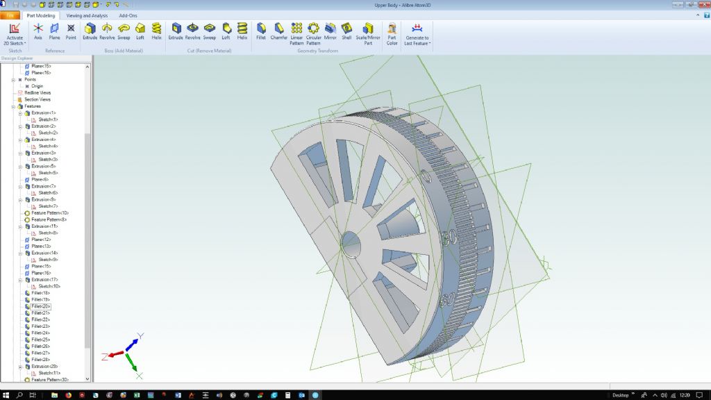
                                        I've worked out how to do boss revolve with something I drew in Alibre, but I want to import the profile, then position it relative to axis and rotate

                                        screendump.jpg

                                        Edited By duncan webster on 25/11/2018 13:36:03

                                        #382270
                                        JasonB
                                        Moderator
                                          @jasonb

                                          David will have to help with this one as like you when I go to open it just opens a DXF or DWG drawing and does not open the drawing as a sketch. I think I used to be able to do it with import.

                                          #382275
                                          JasonB
                                          Moderator
                                            @jasonb

                                            Done it, will come back to you after the F1

                                            #382282
                                            JasonB
                                            Moderator
                                              @jasonb

                                              So basically use Atom to open the DXF or DWG file, check units and that both boxes are ticked.

                                              Once you have the drawing up on screen select Activate 2D sketch which will put the red box around the drawing, then select all which will turn the lines blue (shift and click for individual lines) and then Copy. minimise that screen.

                                              Open up a new part and activate 2D sketch followed by selecting the plane, paste the previously copied item which gives you your new sketch, deactivate sketch.

                                              Select revolve and your axis.

                                              #382285
                                              David Jupp
                                              Participant
                                                @davidjupp51506

                                                To use the reference geometry of parts with assembly constraints, you have to right click on part in assembly (in workspace or in Design Explorer) then select 'Show Reference Geometry'.

                                                If you start to build assemblies in this way, you'll soon realise (like Andrew mentioned) that you can save a lot of time by choosing carefully how to build the individual parts – that that reference geometry is already in a convenient position.

                                                I make nearly all my parts to have at least some symmetry across one of the default planes – but you don't want to worry about that when struggling to make your first parts.

                                                #382306
                                                John Hinkley
                                                Participant
                                                  @johnhinkley26699

                                                  Andrew and David,

                                                  Thank you both for the informative posts. Like I said, I'm still in the foothills, but all these useful tips will – eventually – sink in and hopefully I'll get better organised in future.

                                                  John

                                                  #382307
                                                  duncan webster 1
                                                  Participant
                                                    @duncanwebster1

                                                    Success I think. Followed Jason's instructions and got the section into a sketch, but it is complaining that it is position/magnitude undefined, even tho I've put it in the correct position referred to the origin

                                                    section.jpg

                                                    It did the revolve bit OK, but are there hidden difficulties?

                                                    model.jpg

                                                    If not I'll continue and add the balance weights.

                                                    Must admit I'm enjoying this, even if I do keep asking dumb questions

                                                    #382312
                                                    mick
                                                    Participant
                                                      @mick65121

                                                      Back to basics. I'm trying to assemble the four components of the crank assembly exercise. I can move the wheel until the through holes are in the correct orientation, click and Esc. When I open the link it appears as a cross and there doesn't appear to be any way of changing its orientation without changing the orientation of the wheel. I've tried opening the link first and positioning it in the correct orientation for assembly. The crank handle is the only component that opens in the correct position in relation to the link. I've tried going back to the files and making sure that the component is saved in the correct orientation but when opened for assembly I get the same problem. I suspect I must have missed something when I was generating and saving the components. Thanks

                                                    Viewing 25 posts - 226 through 250 (of 841 total)
                                                    • Please log in to reply to this topic. Registering is free and easy using the links on the menu at the top of this page.

                                                    Advert

                                                    Latest Replies

                                                    Viewing 25 topics - 1 through 25 (of 25 total)
                                                    Viewing 25 topics - 1 through 25 (of 25 total)

                                                    View full reply list.

                                                    Advert

                                                    Newsletter Sign-up