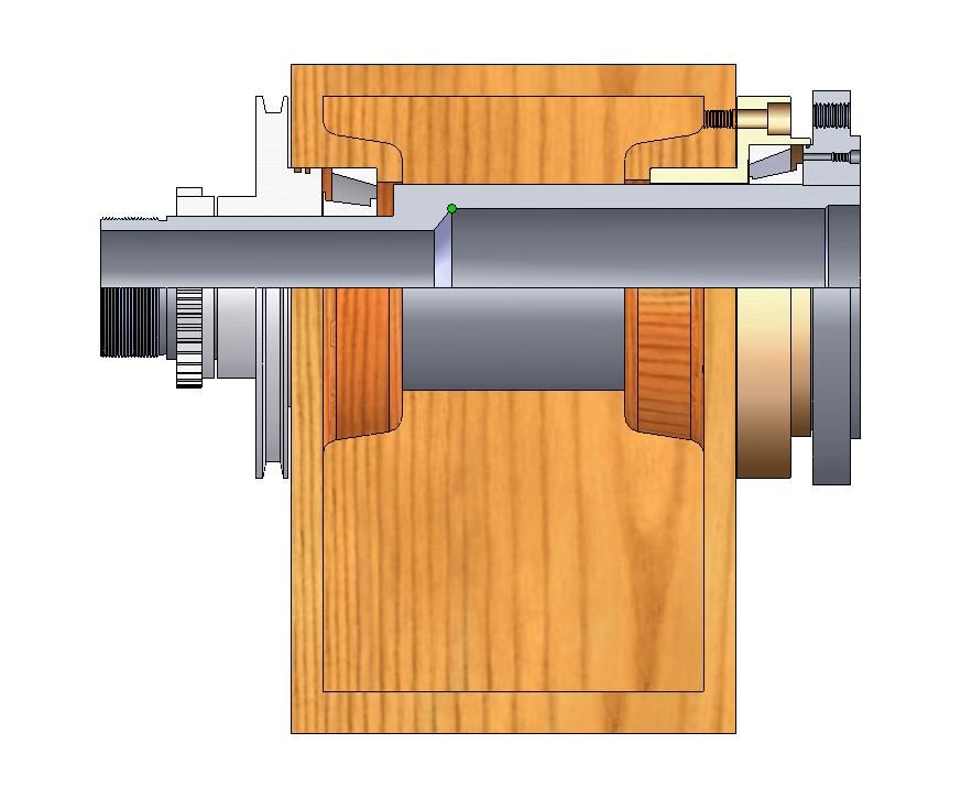
Lathe Rigidity Issues – Modification Opinions

Advert

Lathe Rigidity Issues – Modification Opinions

Home Forums CNC machines, Home builds, Conversions, ELS, automation, software, etc tools Lathe Rigidity Issues – Modification Opinions

Viewing 25 posts - 26 through 50 (of 51 total)
  • Author
    Posts
  • #534804
    Hopper
    Participant
      @hopper

      While you have it apart you might as well ditch the Chinese bearings and put in some good quality SKF or similar. Not all bearings are created equal.

      If the headstock is removeable from the bed it would be worthwhile to blue up the mating surfaces and scrape for a good matching fit. As you have seen, they are not finished to old time precision standards by the factory so could be moving about a bit on poorly matched surfaces. Then of course you have to check spindle alignment to bed etc.

      Welding sounds kinda radical and could bring heat distortion into play etc. A firm seating on the ways should do the job, you would think.

      It probably should do those smaller diamter threads better than the big diameter piston job, once you have all the littte things tightened up. Modern insert tooling works pretty well for screwcutting.

      Edited By Hopper on 19/03/2021 07:02:14

      Advert
      #534811
      JasonB
      Moderator
        @jasonb

        Simple way to get rid of the 0.004" gap would be to mill that amount off the half of the plate that mates to the carriage but leave full thickness where it runs against the underside of the bed, the step will raise the running surface up 4thou.

        Do check that the bed is constant thickness along it's length, may need a bit of scraping on the underside.

        #534815
        John Haine
        Participant
          @johnhaine32865

          toolpost3.jpg

          #534865
          Dave Halford
          Participant
            @davehalford22513
            Posted by Dave Halford on 18/03/2021 11:33:28:

            Firstly skim the plate seating (not the saddle) on the back of the saddle so you have minimal clearance, that will stop the saddle lifting and dropping and lifting ——- in time with you chatter. This is due to the front being forced down by the cut which can't move and so the back is lifted instead, which raises your tool height, and stops cutting.

            Edited By Dave Halford on 18/03/2021 11:34:16

            Jason,

            You said it better than I did smiley

            #534869
            Oily Rag
            Participant
              @oilyrag

              Ed,

              First time I have looked at your post but certain things come to mind straight away.

              1. Mounting the lathe on a wooden table/cabinet will not help. I would make a substantial RSJ stand for it and bolt it down with adjustments for bed twist.

              2. The 4th picture in your OP shows the external gripping chuck jaws at more extension than I would like to see, looks like you need a bigger chuck! Workholding can exacerbate chatter if not secure.

              3. Have you considered a rear toolpost? An inverted tool in a rear post will work with you, reducing chatter as the cross slide will lift and tighten onto the dovetails.

              Apologies if anyone has mentioned these points previously.

              Martin

              #534888
              Niels Abildgaard
              Participant
                @nielsabildgaard33719
                Posted by Niels Abildgaard on 18/03/2021 10:46:52:

                The lathe is a 26mm bore 250 size like the much loved one I had before my son liberated it.He will get a surprice when estate is parted.

                A good advice to Niels:

                Do your homework before touching keyboard. The CQ6128X660A lathe is 280 size with 660mm between points.

                This is more or less a Brother of JasonB s.But a smaller 26mm spindle I think.

                #534896
                Ex contributor
                Participant
                  @mgnbuk

                  I am thinking of something spring loaded

                  No !. Why introduce the possibliity of unwanted movement when load increases ?

                  Just make the strips (plural – there should also be one under the front shear) fit properly, no need to add fudges that will come back to bite you. When properly sorted, the only way the saddle should be able to move is longitudinally along the bed – no lift, no twisting.

                  As Jason suggested, the easiest way is to take the 4 thou of the part of strip surface that the bolts to the saddle.

                  Weld the headstock to the bed – really ?

                  Nigel B.

                  #534905
                  Cabinet Enforcer
                  Participant
                    @cabinetenforcer
                    Posted by Niels Abildgaard on 19/03/2021 13:55:54:

                    This is more or less a Brother of JasonB s.But a smaller 26mm spindle I think.

                    AFAIK all 280s have a 26mm through hole on the spindle, only the 290s have the bigger bearings and larger 31mm spindle. The Chinese one-upmanship that has resulted in the big bore 250s doesn't seem to have hit the 280 class yet.

                    #534916
                    Niels Abildgaard
                    Participant
                      @nielsabildgaard33719
                      Posted by Cabinet Enforcer on 19/03/2021 16:15:01:

                      AFAIK all 280s have a 26mm through hole on the spindle, only the 290s have the bigger bearings and larger 31mm spindle. The Chinese one-upmanship that has resulted in the big bore 250s doesn't seem to have hit the 280 class yet.

                      It is  an offence to us underpriviledged citizens in not going to the moon soon countries ,to ofload us so much iron and then put such a small knitting neddle spindle in.

                      As luck have it I can offer two solutions that do not need any change of headstock.

                      Please enjoy.

                      dok 75 cantilever.jpg

                      total stikleje.jpg

                      Edited By Niels Abildgaard on 19/03/2021 16:51:32

                      Edited By Niels Abildgaard on 19/03/2021 16:53:32

                      Edited By Niels Abildgaard on 19/03/2021 16:54:04

                      Edited By Niels Abildgaard on 19/03/2021 16:54:41

                      #534962
                      Ed Page
                      Participant
                        @edpage45070

                        saddle.jpg20210319_145039.jpg20210319_150549.jpg20210319_152129.jpg20210319_153844.jpg

                        I should have a two updates today, the first being that I milled down the gib strips for underneath the bed. Thankfully I did not screw the scraping up as I removed 4 thou on one strip and 4.5 thou on the other. That resulted in a lift of 0.8 thou on the front and 0.2 thou on the back, slides nicely on the full length of the bed, this part is at least well ground.

                        I did some searching last night on standard taper bearings, so I might pick up some SKF ones or even possibly upgrade the spindle slightly as in Niels post to a beefier setup. I have a threaded mandrel which I originally used to hold the piston, then I changed jaws to hold on the outside to see if that improved it, it did not, I also used a live centre for all operations, a good quality one. I do agree my bench is a little underwhelming, but I can sort that after I've tuned the lathe. I was also joking about the welding , plus you need iron hot to weld it good.

                        I have done some designing for a piece to bolt onto the top slide, made from 6 x 2 x 12.5 steel, a left over, quite a lot of milling to do so hopefully I will get some pictures tonight. I chose lots of slots and tapped holes for lots of arrangements as I intend to use gang tooling. The swing over slide is now 142mm, just enough to do some 140mm diameter tubes, which I have already done without issue.

                        #534978
                        Ed Page
                        Participant
                          @edpage45070

                          20210319_194404.jpg20210319_210233.jpg20210319_210237.jpg

                          Little bit of milling and 62 holes later the bottom side is done.

                          #534979
                          Hopper
                          Participant
                            @hopper

                            Wow that's shifting some metal. What milling machine do you have.?

                            I would go with replacing the existing size bearings with SKF.

                            Bolt on external bearing carriers might allow bigger bearings but are only as rigid as the thinnest wall in the carrier piece. Which is thinner than the headstock casting.

                            Edited By Hopper on 20/03/2021 03:41:16

                            #534980
                            Ed Page
                            Participant
                              @edpage45070

                              I'll have to take a picture of the mill, it's a Fulland Mill, 1985, Taiwan machine, not sure of the model number, about the same size as a Bridgeport. Maximum spindle speed is 3500rpm, so a little limited. I did a 23mm depth of cut, 0.6mm stepover, 80 IPM, 7/16 carbide end mill. Took about 45 minutes to do the milling, and then about 1hr to do the drilling. Running on Mach4 and using fusion 360. Fusion retracts out all the way for each pass whereas Mastercam micro lifts and back traces the previous cut, I think I could have got it down to 30 minute on that software with this machine, but that's the limit, plus I can't afford Mastercam.

                              I think you're right in regards to the spindle bearings. I have started designing my own machine so don't want to go too crazy with this one, in terms of money. I think the external carrier would add some rigidity, but ultimately the castings will let it down. I have also considered filling all of the castings with concrete, or maybe some kind of sand/resin mix, I think that would also dampen the whole thing, wouldn't be all that expensive either.

                              #534981
                              Hopper
                              Participant
                                @hopper

                                Or maybe rather than throwing the baby out woth the bathwater, get some 1" steel plate laser/waterjet cut to shape and weld up your own headstock to fit the existing bed. Looks like you have the milling facilities to bore the bearing holes and cut the ways to sit on the bed.

                                #534985
                                JasonB
                                Moderator
                                  @jasonb

                                  Ed, have you seen Joe's current lathe build thread?

                                  #535001
                                  John Haine
                                  Participant
                                    @johnhaine32865

                                    Before the Myford I had a Mashtroy 220 lathe that gave a horrible finish and would not part anything at any speed. After worrying at it for quite a while I noticed that there was a distinctly gritty feel to the bearings so I too out the spindle and the roller races were quite badly marked even though the lathe was quite new. Then I bugged the supplier to replace the bearings until he sent me some decent ones which transformed it.

                                    I think you said the lathe was CNC? Why do you need a topslide at all?

                                    #535016
                                    John Haine
                                    Participant
                                      @johnhaine32865

                                      I meant to add – how do you keep swarf out of the ballscrews?

                                      #535054
                                      Howard Lewis
                                      Participant
                                        @howardlewis46836

                                        Coming in LATE without having read all of the posts.

                                        Has your lathe got Back Gear?

                                        Unless my calculations are off, turning a 5" diameter at 150 rpm gives surface speed of 196 fpm

                                        To my mind, that seems much too fast for steel, particularly with a wide tool, hence the chatter.

                                        If no Back Gear, but belt drive, make up new pulleys and new belt o slow the speed to under 75 rpm?

                                        What are your thoughts?

                                        Howard

                                        #535123
                                        Ed Page
                                        Participant
                                          @edpage45070

                                          20210320_154100.jpg20210320_155138.jpg20210320_183411.jpg20210320_184345.jpg20210320_184409.jpg

                                          Another update on the build, finally got the top slide done, although I need to cut the bolts down. Note that the holes on the slide are offset to one end because I milled through some original holes to make the bolt pattern symetrical. I used an old HSS chamfer tool which left huge burs on the slots, they were not fun to file. Overall it looks pretty good, I turned about half the original mass into chips. The lathe also has a huge amount of travel on the slide and plenty of space for front and rear tooling.

                                          To address a few questions and comments. Joes build on his CNC is absolutely amazing, can't wait to see it running, and really interested to see his tool changer design. Looks like he used the same supplier for his servo's as me, and that is the same spindle / servo I'm thinking about for the drive. Not worried about swarf on the screws, they have wipers, would be a little more concerned if I were doing iron or grinding. I might make a completely new head for the lathe as Hopper suggested and leave my own lathe build for another time. I'll make an adapter plate so I can swap this new head over to the other lathe in the future. I'm more concerned about spindle bore, which I need to pass 2 inch down. So my current design uses a 2.6" bore, 8 inch chuck and two 80 x 135mm taper roller bearings.

                                          #535144
                                          Niels Abildgaard
                                          Participant
                                            @nielsabildgaard33719
                                            Posted by Ed Page on 21/03/2021 01:16:20:
                                             
                                            I'm more concerned about spindle bore, which I need to pass 2 inch down. So my current design uses a 2.6" bore, 8 inch chuck and two 80 x 135mm taper roller bearings.

                                            I have been thinking very hard how to make my next 62mm bearing bore lathe more capable.Main problem is to make a system of mandrels holding front bearing holder while Chokfast,Non-shrinking loctite or epoxy sets without locking up tool as well.

                                            On the other hand it is only for the brave or rich as it will not be possible to go back.

                                            You can se on picture that the bearing bore stop on front bearing hole has to go.Not a precission job but non recovedokmega. 32915 32910 jpg.jpgrable.

                                            While I am at it it is no big deal to show how it can look on a 290 lathe with 75mm bores.

                                            Edited By Niels Abildgaard on 21/03/2021 08:38:55

                                            #536820
                                            Ed Page
                                            Participant
                                              @edpage45070

                                              20210327_145834.jpg20210328_123703.jpg20210328_143108.jpg20210328_144450.jpg20210328_145408.jpg

                                              Quick update, took me all week to find a bandsaw, so I could finally cut some blocks for the holders. Also waiting on some SKF spindle bearings, surprisingly the stock ones were NSK, but full of paint flecks. Might have gone a little over-kill on the holders, but will allow most tooling setups and a second spindle. Will be keeping the stock spindle and build a second spindle to bolt to the other end of the bed, for larger stuff. Waiting on my encode too, but hopefully in another week I'll be threading. I also really hate hand tapping holes now!

                                              #536828
                                              JasonB
                                              Moderator
                                                @jasonb

                                                Interesting choice in mounting methods. I would have thought the slot for nut access reduced rigidity of the tool holders when the thread seems to be about increasing rigidity. Would through holes on the tailstock side of the holders for HT bolts or cap heads have been a better option?

                                                #536833
                                                Ady1
                                                Participant
                                                  @ady1

                                                  Forgot about a Drummond mod which noticeably improved spindle stiffness

                                                  #536838
                                                  Tony Pratt 1
                                                  Participant
                                                    @tonypratt1
                                                    Posted by JasonB on 29/03/2021 07:32:55:

                                                    Interesting choice in mounting methods. I would have thought the slot for nut access reduced rigidity of the tool holders when the thread seems to be about increasing rigidity. Would through holes on the tailstock side of the holders for HT bolts or cap heads have been a better option?

                                                    I hate to rain on Ed's parade but Jason is spot on.

                                                    Tony

                                                    #536847
                                                    Ed Page
                                                    Participant
                                                      @edpage45070

                                                      I did fear the slot being close to the bottom would reduce rigidity, counter intuitive to what this thread is about. I chose studs over bolts at the back of the holder to reduce wear, / cheaper to replace, but in reality I probably would never wear them out. The base of the holder is 0.5 inch thick by 4 inch long, that would take a huge amount of effort to flex it, especially on a hobby lathe. Also consider a QCTP holder has about the same thickness underneath.

                                                      Worst case if this is a mistake then I will modify for long bolts and fill in the grooves with lead to dampen the holders. Might even do one as a comparison for my own curiosity.

                                                    Viewing 25 posts - 26 through 50 (of 51 total)
                                                    • Please log in to reply to this topic. Registering is free and easy using the links on the menu at the top of this page.

                                                    Advert

                                                    Latest Replies

                                                    Viewing 25 topics - 1 through 25 (of 25 total)
                                                    Viewing 25 topics - 1 through 25 (of 25 total)

                                                    View full reply list.

                                                    Advert

                                                    Newsletter Sign-up