Lathe help information
Lathe help information
- This topic has 26 replies, 14 voices, and was last updated 25 February 2025 at 18:46 by
 Pete Rimmer.
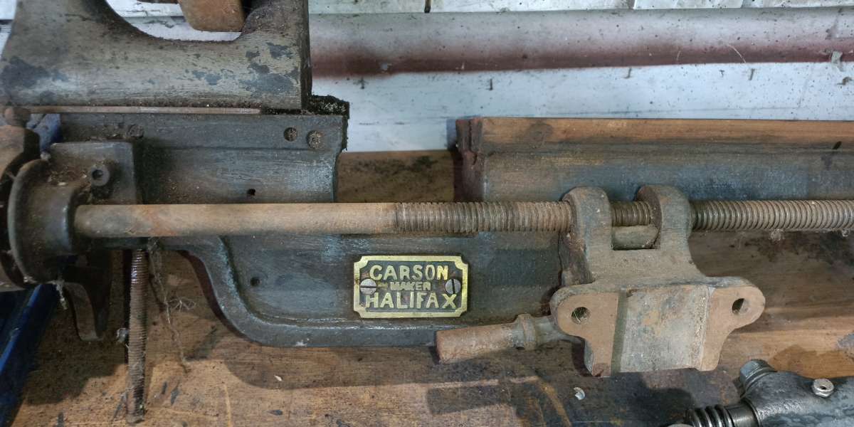

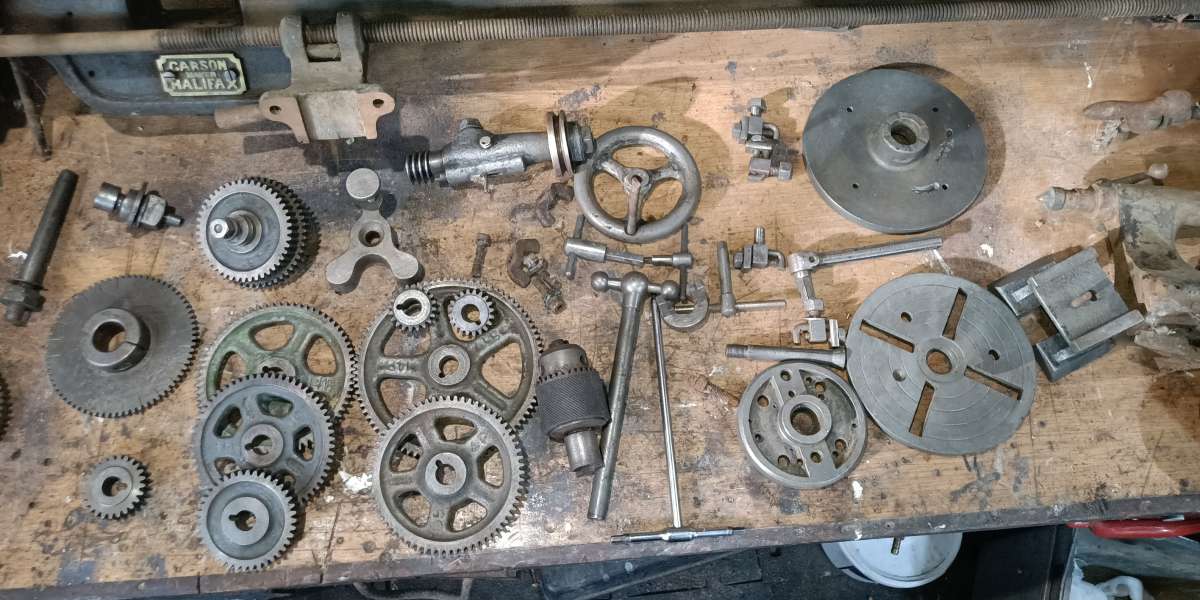
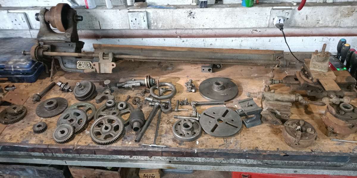
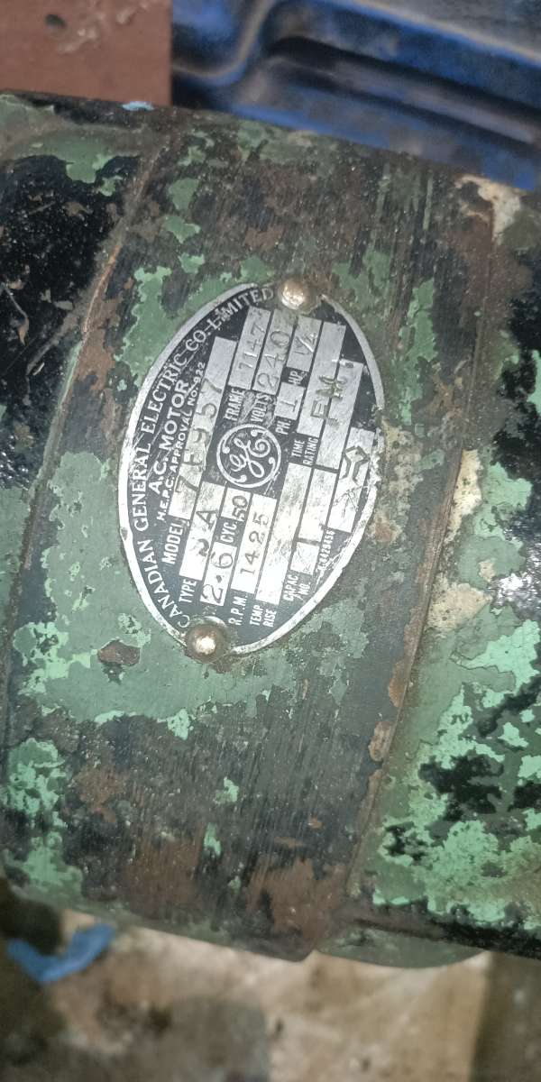
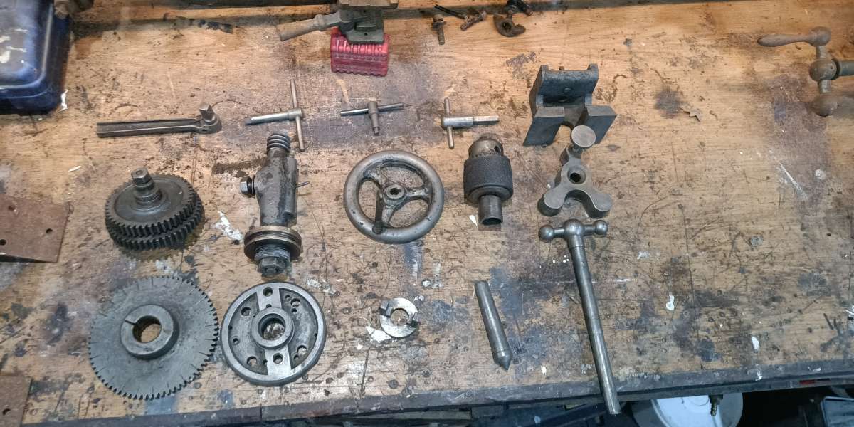
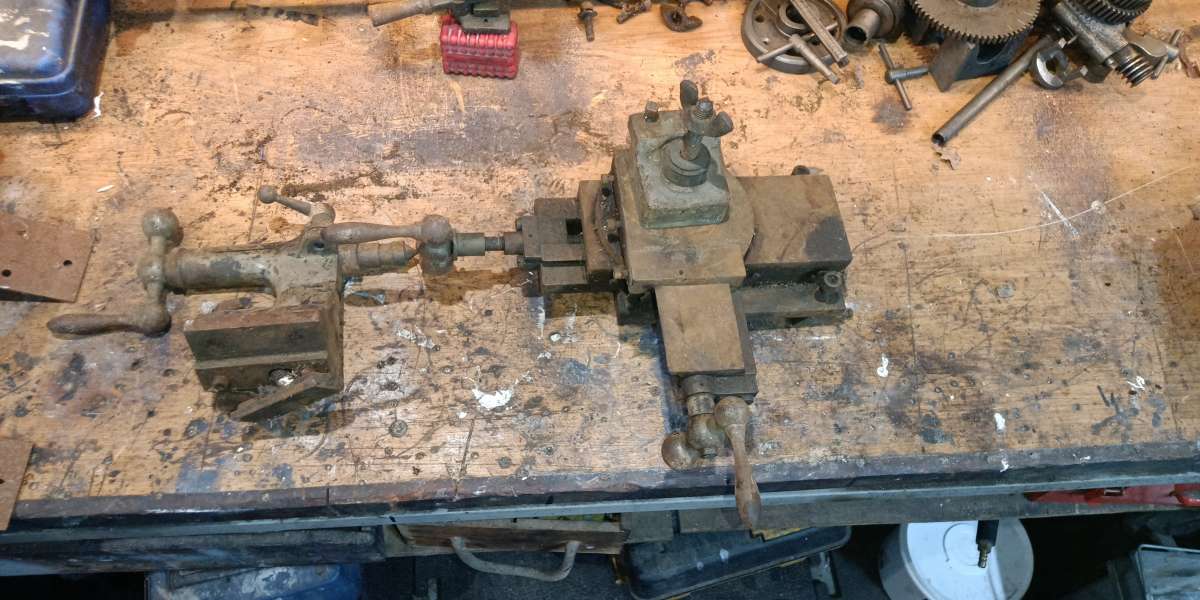
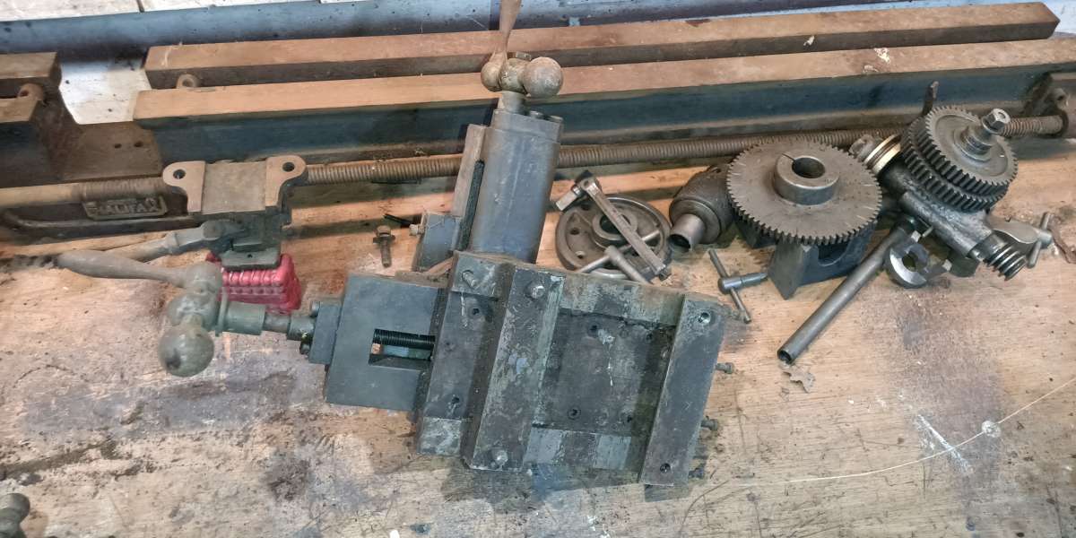
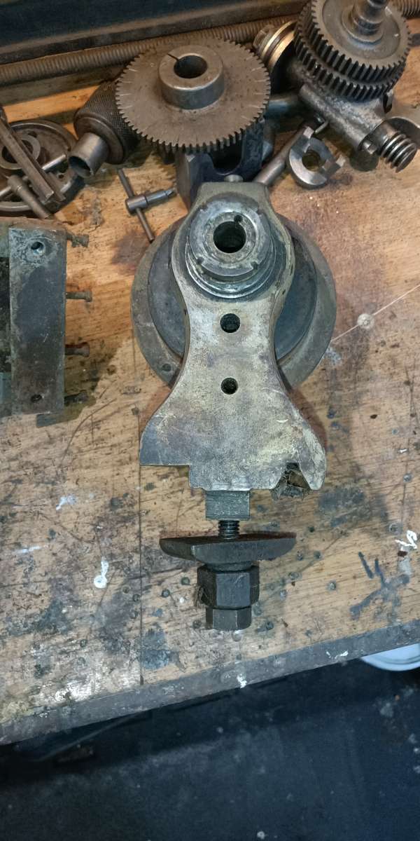
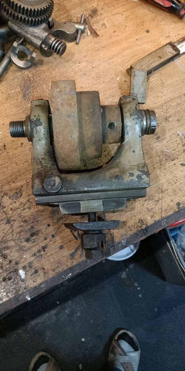
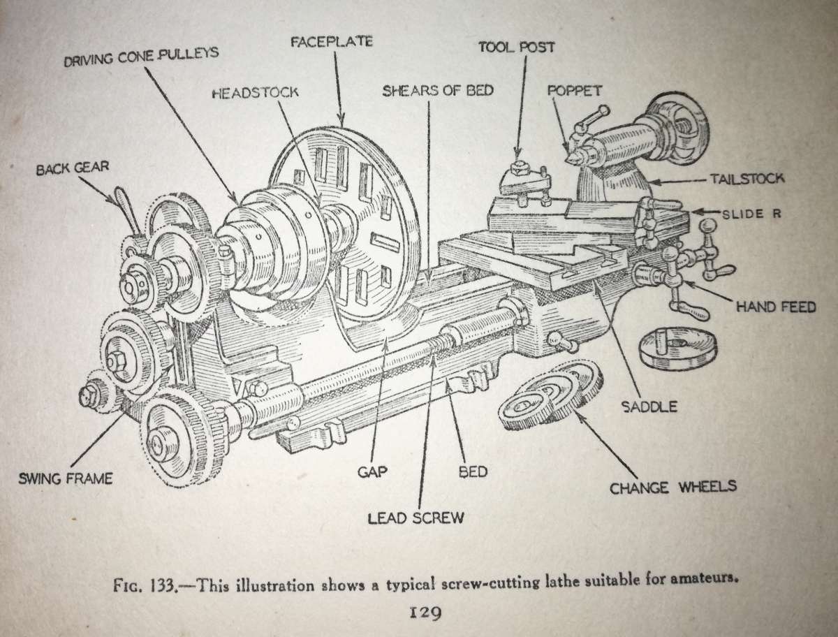
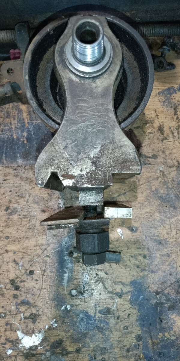
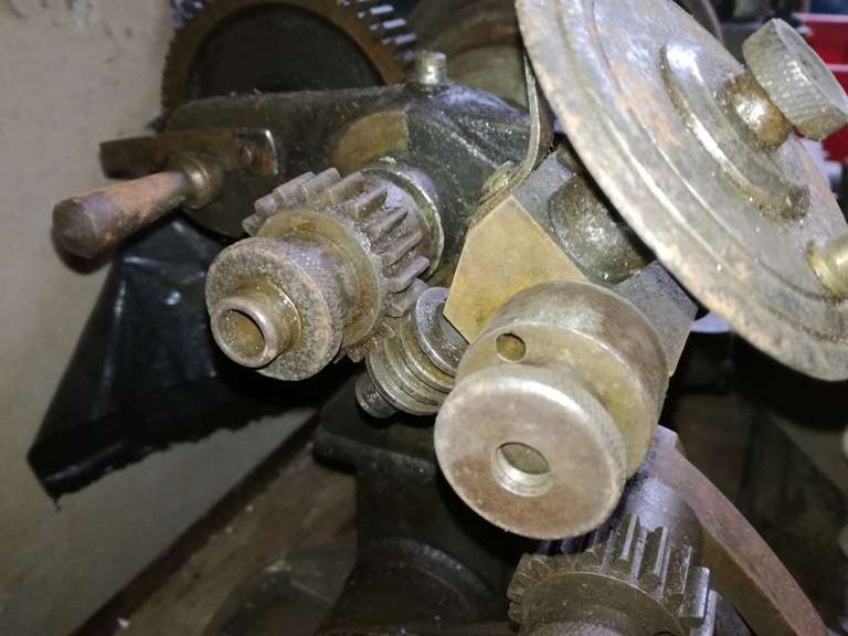
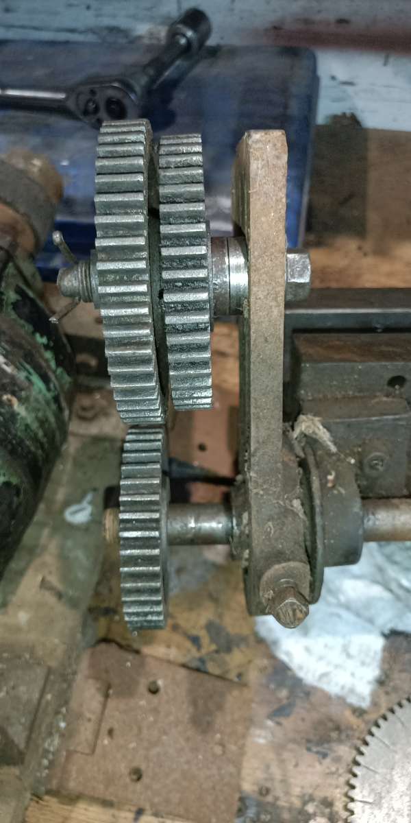
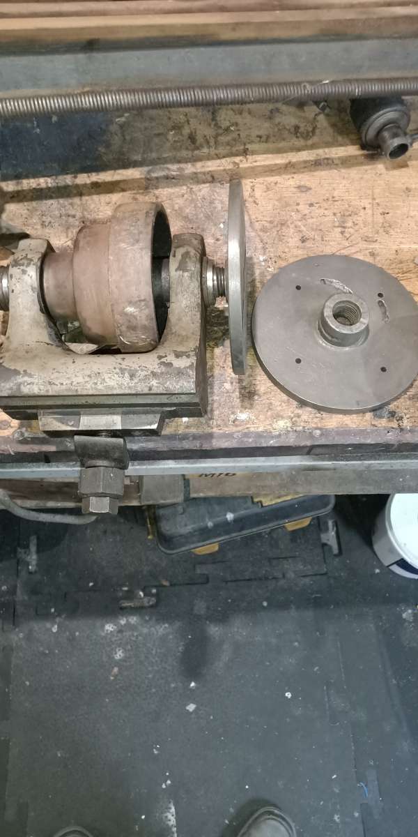
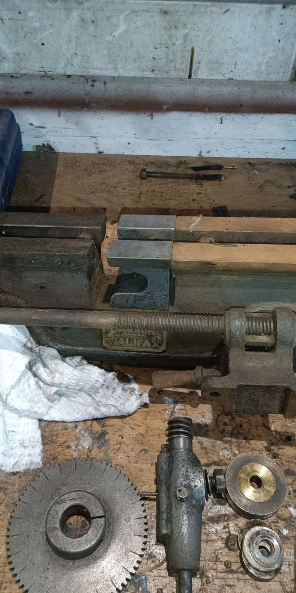
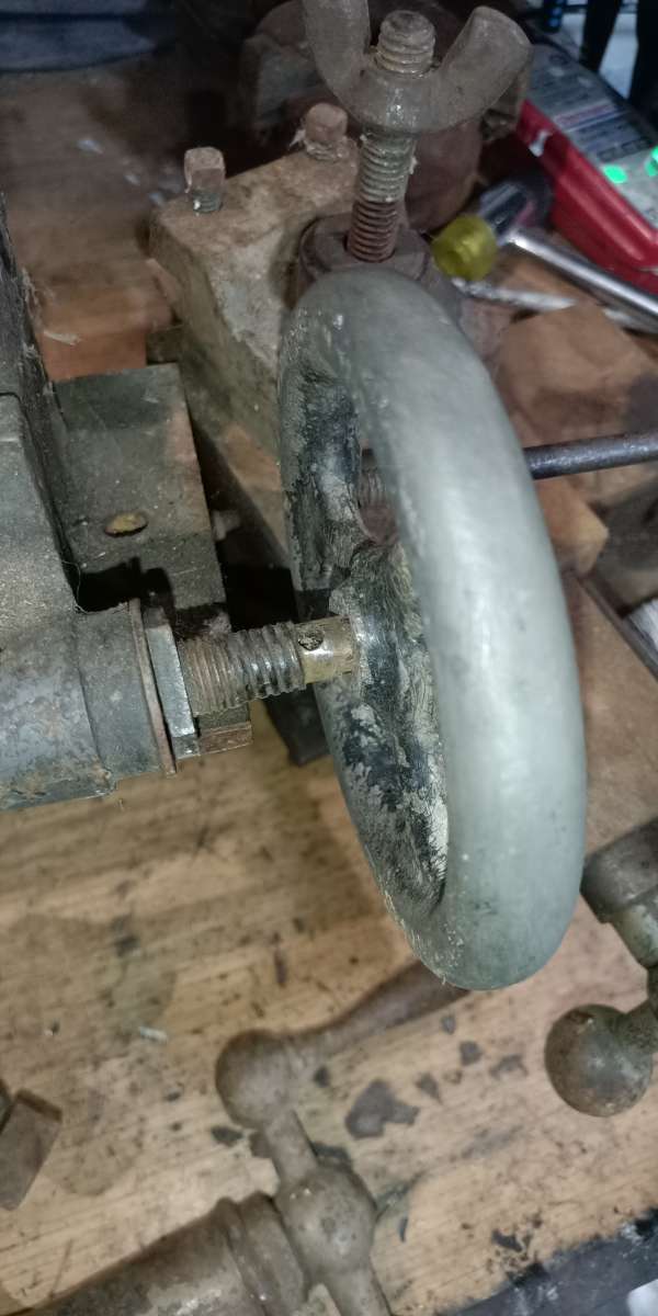
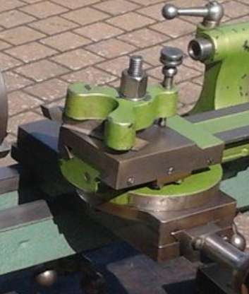
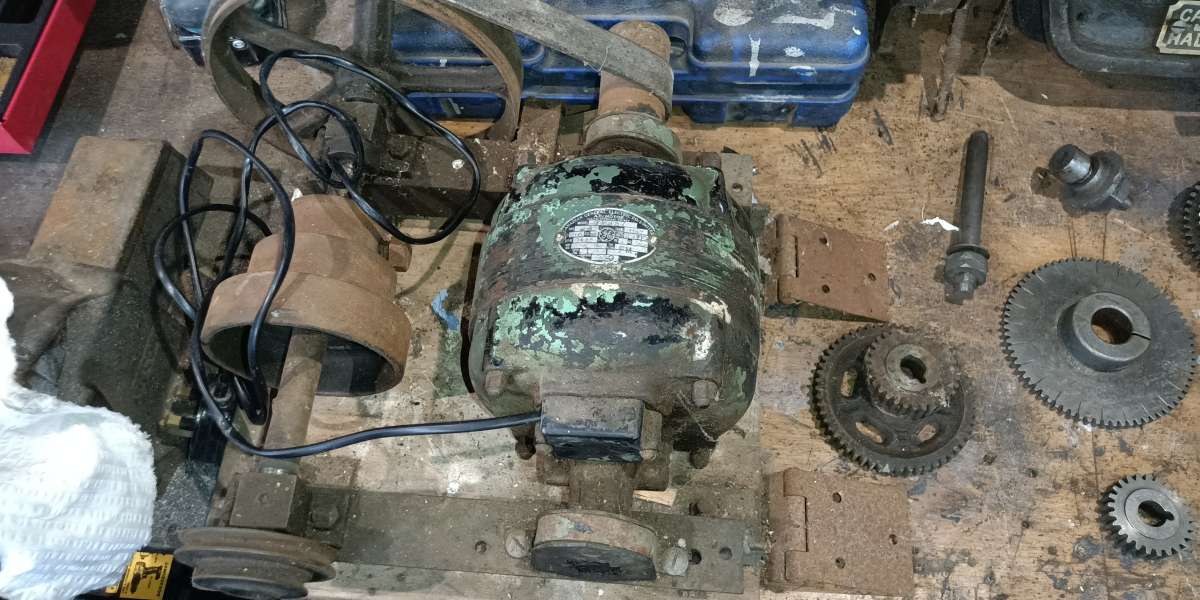 gs but for the life of me can’t see how the link from the spindle forgive me if I get terminology wrong I have 0 knowledge on lathes.
- Please log in to reply to this topic. Registering is free and easy using the links on the menu at the top of this page.
Latest Replies
-
- Topic
- Voices
- Last Post
-
-
Adding a quill lock to a drill press
Started by:
beeza650
in: Manual machine tools
- 3
-
21 July 2025 at 20:46
beeza650
-
Arc Euro Trade Ltd.
Started by:
Ketan Swali
in: General Questions
- 19
-
21 July 2025 at 20:13
not done it yet
-
Amadeal lathes – Any good??
1
2
Started by:
Tim Sallows
in: Workshop Tools and Tooling
- 16
-
21 July 2025 at 19:16
JasonB
-
Issue 4767 and links
Started by:
Andy Stopford
in: Model Engineer & Workshop
- 2
-
21 July 2025 at 19:14
JasonB
-
Pipe bending by hand versus pipe bending tools
Started by:
Greensands
in: Workshop Tools and Tooling
- 2
-
21 July 2025 at 18:58
vintagengineer
-
Round Bar Bender
Started by:
Trevor Howley
in: Workshop Tools and Tooling
- 1
-
21 July 2025 at 18:46
Trevor Howley
-
My vise isn’t at 90 degrees
Started by:
moonman
in: Beginners questions
- 15
-
21 July 2025 at 15:41
JasonB
-
5 inch gauge Stirling single
Started by:
Michael Callaghan
in: Locomotives
- 5
-
21 July 2025 at 15:37
Michael Callaghan
-
Diving in to ATC?
Started by:
Steve355
in: CNC machines, Home builds, Conversions, ELS, automation, software, etc tools
- 4
-
21 July 2025 at 14:55
Martin Connelly
-
Hopeless…Alibre Ass
Started by:
Nigel Graham 2
in: CAD – Technical drawing & design
- 6
-
21 July 2025 at 14:40
blowlamp
-
Edward Thomas excessive wheel slip
Started by:
Ian R
in: Locomotives
- 3
-
21 July 2025 at 14:11
Ian R
-
Hofmann Rollers
Started by:
Martin Kyte
in: General Questions
- 11
-
21 July 2025 at 13:07
DC31k
-
Herbert B drill information?
Started by:
Andrew Tinsley
in: Workshop Tools and Tooling
- 4
-
21 July 2025 at 12:45
Michael Gilligan
-
What’s in the archive?
Started by:
Michael Callaghan
in: General Questions
- 2
-
21 July 2025 at 12:36
Michael Callaghan
-
Myford S7 VFD problem
1
2
Started by:
Glyn Davies
in: Manual machine tools
- 21
-
21 July 2025 at 10:36
Glyn Davies
-
Model Engine running just off a naked flame
Started by:
Blue Heeler
in: Stationary engines
- 6
-
21 July 2025 at 09:26
JasonB
-
Model Engineer Magazine Collection
Started by:
mfengine1
in: Books
- 9
-
21 July 2025 at 09:22
Norman Blackburn 1
-
Panorama : Fighting Cyber Criminals
Started by:
Michael Gilligan
in: The Tea Room
- 2
-
21 July 2025 at 09:20
Nigel Graham 2
-
Lidl castors
Started by:
Michael Gilligan
in: The Tea Room
- 5
-
21 July 2025 at 07:30
larry phelan 1
-
Redwing Cylinder head
Started by:
Durhambuilder
in: I/C Engines
- 3
-
21 July 2025 at 07:24
David George 1
-
What Did You Do Today 2025
1
2
…
8
9
Started by:
JasonB
in: The Tea Room
- 33
-
20 July 2025 at 21:39
Dalboy
-
Polishing compounds for stainless steel (mild abrasives))
Started by:
Simon Williams 3
in: Beginners questions
- 13
-
20 July 2025 at 20:02
Russell Eberhardt
-
Bad design, or am I missing something?
Started by:
half whit
in: Beginners questions
- 5
-
20 July 2025 at 19:16
Julie Ann
-
Mistry dividing attachment
1
2
Started by:
Brian Merrifield
in: Workshop Tools and Tooling
- 17
-
20 July 2025 at 18:43
Tony Jeffree
-
Epoxy or acid etch primer
Started by:
Michael Callaghan
in: Materials
- 1
-
20 July 2025 at 16:46
Michael Callaghan
-
Adding a quill lock to a drill press


