Lathe facing convex or concave

Advert

Lathe facing convex or concave

Home Forums General Questions Lathe facing convex or concave

Viewing 25 posts - 76 through 100 (of 107 total)
  • Author
    Posts
  • #147889
    Mark C
    Participant
      @markc

      Graham, never thought I would find myself agreeing with a toolmaker about tolerances but there you go, perhaps you toolmaker types are evolving into designers?

      Mark

      PS. have to agree about AEC, I have a fondness for the Mercury.

      Advert
      #147890
      jason udall
      Participant
        @jasonudall57142

        This subject has strayed into the realms of religion ..almost

        As to facing and the finished part. .it is poor design to require a face to be dead flat (when drawn that way it is a drawing office short cut )
        Any two parts would be designed without that requirement unless really needed.
        Face concave..maybe but better still design with contact as required and clearance else where..
        Now as to how to measure/verify the main cross slide. .now thats much more interesting. .
        Discuss

        #147893
        Mark C
        Participant
          @markc

          Jason, as Graham mentioned the convention is to face a disc and measure along a diameter. If you really wanted to "map" the deviation you could use slips on a ref. plane as you would check a straight edge (put two slips with a suitable height difference at each end and then measure the position/height along the span).

          Mark

          #147894
          MICHAEL WILLIAMS
          Participant
            @michaelwilliams41215

            Tony Pratt ,

            Hi – I’ve sent you a pm . Very short but explains much .

            Regards ,

            Michael Williams .

            #147899
            John McNamara
            Participant
              @johnmcnamara74883

              Hi All

              So The Cavaliers and roundheads are at it again….

              Anyway…. If you want to check the accuracy of the saddle in relation to the plane at 90 degrees to the spindle axis, all you need is a known to be accurate straight edge long enough to be near the maximum swing of your lathe and for ease of use a 4 jaw chuck and a dial indicator.

              Lightly grip the straight edge in the 4 jaw, (use soft but firm packers to protect your straight edge) then adjust the straight edge to touch and deflect a dial indicator tip set on the saddle at the centreline of the spindle. touching near one end of the test straight edge. Keep adjusting the straight edge until it deflects the indicator the same amount (Exactly) when touching near both ends of the 180deg rotated straight edge. At this point do not move the saddle or cross slide.

              Then set the straight edge flat and level (Be careful not to move or knock it) and by traversing the cross slide with the indicator sliding along the straight edge you can check for any lateral movement errors of the cross slide. Any concavity or convexity will show up, You may find the slope is not linear if the lathe is old, the travel may wander sideways.

              As mentioned in a previous post in this thread you have to first (know) the spindle axis is exactly in line with the bed axis. Do this with a test bar as previously described.

              Both this and the axis test are interrelated. Yes this is art as well as science.

              Regards
              John

              #147906
              speelwerk
              Participant
                @speelwerk

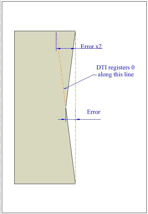
                Well I probably see it wrong being on mainland Europe, but if you face a large diameter and than run a DTI across the whole diameter it will show any deviation from flat. The first halve from where you have started the cut to the centre will measure of course and hopefully zero. But if you pass the centre and move the crosslide with DTI to the other side of the faced part it will show (+) double the devation if the part is convex and (-) halve the deviation if the part is faced concave. Niko.

                Edited By speelwerk on 24/03/2014 13:13:32

                #147907
                blowlamp
                Participant
                  @blowlamp
                  Posted by Nobby on 24/03/2014 10:18:53:

                  HI Niko & Guys
                  If you faced a large Diameter using cross slide . and it faced a slight angle . running a dti across the face using
                  the same cross slide. surly it would follow the same path ie zero . ?
                  Nobby

                  It'll depend upon which side you run the clock, Nobby.

                  Clocking the front side should give a zero reading if the tool was sharp and also took a full cut, but if you run the clock on the back (other side of the axis), it should show double the actual error.

                  Martin.

                  #147921
                  Gary Wooding
                  Participant
                    @garywooding25363
                    Posted by Nobby on 24/03/2014 10:18:53:

                    HI Niko & Guys
                    If you faced a large Diameter using cross slide . and it faced a slight angle . running a dti across the face using
                    the same cross slide. surly it would follow the same path ie zero . ?
                    Nobby

                    Quite so, if you only went to the centre; but if you went right across the face, the DTI would register twice the error when you reached the other side.

                    Gary

                    #147924
                    Nobby
                    Participant
                      @nobby

                      Hi Gary Martin & Guys

                      That,s fine I should have given it more thought it,s my age !!!! I will try it tomorrow Tue 25th . on my S7 , Mk1
                      Nobby

                      #147952
                      John McNamara
                      Participant
                        @johnmcnamara74883

                        Hi All

                        Not many lathes can traverse the cross slide much past the centre line. Using a dial indicator on a freshly the turned face should show minimal or zero error. It is just replacing the tool. and replicating any error

                        That is why the straight edge method is normally used for testing, as long as you know it is straight it is a reference independent of the lathe itself, it is very easy to set it up to be at exactly 90 degrees to the spindle axis.

                        It allows you to test the entire travel of the cross slide for both straightness, and if it faces at exactly 90 degrees, or faces concave or convex.

                        With a sufficiently large disk you are prepared to sacrifice you can face it then check for concave or convex with gauge blocks or feelers against a straight edge applied across that face. A similar result to the straight edge method above but a lot slower and difficult to do accurately.

                        What I find interesting when doing any testing is to graph the results with excel or graph paper. When doing a test write down the results every say 5mm then graph them. If you think you are going to get a straight line with this facing test you are in for a surprise, unless the lathe is in very good condition and from a good maker you are more likely to see the line wavering due to errors in the dovetails or guide rails under the cross slide. You really need an indicator that can resolve .0001 inches for this type of testing.

                        Regards
                        John

                        #147959
                        speelwerk
                        Participant
                          @speelwerk

                          Well, since the first halve of the faced part is zero till the centre line you can turn the crosslide as far out as possible, set the dail near the centre at zero and than move it across the back part. Niko.

                          #147967
                          speelwerk
                          Participant
                            @speelwerk

                            If the lathe faces convex you get twice the error plus, halve minus if it faces concave. Another problem is to get a good quality steel rule, I use them for checking straithnes of musical box combs. When I bought several of them of different length and asked the question what the accuracy was, they where not able to tell me. Niko

                            #147977
                            speelwerk
                            Participant
                              @speelwerk

                              You can clearly read that I have never checked it myself, it should be of course plus twice for convex and minus twice for concave. Niko.

                              #147983
                              John McNamara
                              Participant
                                @johnmcnamara74883

                                Hi All

                                Twice the error?

                                Not really…..You are stopping in the middle of the piece if you are cutting a test disk. The error is simply the error along the radius.

                                Regards
                                John

                                #147984
                                Gary Wooding
                                Participant
                                  @garywooding25363

                                  .


                                  Edited By Gary Wooding on 25/03/2014 07:56:48

                                  Edited By Gary Wooding on 25/03/2014 07:57:57

                                  #147985
                                  Clive Hartland
                                  Participant
                                    @clivehartland94829

                                    What I want to know is how all this will affect the 2mm step on the shaft that I am making? After all most of us only have a model making lathe of approx. 3.5" swing and seldom cut big diameters. I can see that as a test it can prove something so that remedial action can be taken. 2 x the error, its concave or convex and measurable as an error surely.

                                    Clive

                                    #147986
                                    Gary Wooding
                                    Participant
                                      @garywooding25363

                                      This explains it.

                                      Gary

                                      concaveerr.jpg

                                      #147995
                                      MICHAEL WILLIAMS
                                      Participant
                                        @michaelwilliams41215

                                        No argument about the test but before correcting anything on alignment of lathe parts make sure that cause of error is identified properly . Could be many causes but common ones are :

                                        Natural cutting action . Variation of cutting speed radially and tool wear can cause non flat facing anyway if not corrected for .

                                        Loose slides – sometimes biased one way and sometimes another .

                                        Spindle out of line relative to bed axis either because of misaligned headstock or because of worn/poorly adjusted bearings .

                                        Cross slide not at right angles to bed axis or at right angles to the spindle axis as is .

                                        Reference to ‘at right angles’ is in the simple sense and not taking into account any chosen small variation of angle to optimise the whole alignment of lathe when cutting under load .

                                        Facing test needs to be accompanied by a parallel turning test to get real answers .

                                        The question of how flat facing has to be for different purposes has been well discussed .

                                        I’ll just say that the more sophisticated the engineering that is being done the more it matters .

                                        Conversely on small lathes doing model engineering it matters less .

                                        Just what you need at the time really .

                                        Michael Williams .

                                        #147996
                                        speelwerk
                                        Participant
                                          @speelwerk

                                          Thank you very much Gray for letting me know how to check the straigthness, I can blame my instructors for not letting me do that test, but they are now all long gone. Problem is the longest rule I use is 50cm and I only have a small surface table of also unknow accuracy. Niko.

                                          Edited By speelwerk on 25/03/2014 09:31:52

                                          #147998
                                          speelwerk
                                          Participant
                                            @speelwerk

                                            Thanks again Graham, I am sure that that will be more than accurate enough for the work I do, sadly I do not have acces to such equipment. No doubt someone on the forum can sort it out, but I do not think he lives near me in the Netherlands. Niko.

                                            Edited By speelwerk on 25/03/2014 10:06:40

                                            #148000
                                            Michael Gilligan
                                            Participant
                                              @michaelgilligan61133

                                              Niko,

                                              You mentioned, earlier, that you had bought several of the rules/straightedges, so …

                                              A simple check would be to put any two of them edge-to-edge and check for gaps.

                                              Repeat this for every combination/permutation and you should have a pretty good data-set.

                                              … With the option to correct them by filing, if you have the patience

                                              … [not unlike Mr Whitworth's method for making surface plates]

                                              MichaelG.

                                              #148007
                                              speelwerk
                                              Participant
                                                @speelwerk

                                                Yes Michael, that is what I have done when I had them at home, not knowing that that is Mr. Whitworth's method, Niko.

                                                #148012
                                                Neil Wyatt
                                                Moderator
                                                  @neilwyatt

                                                  HI Clive,

                                                  I've been facing 2 3/4" blanks to make wheels for a driving trolley. It doesn't matter that they won't sit flat (although it is irritating). However, I will have two oversize slices of steel left at the end, and I want one to become a bench block. It will need good flat and parallel faces if it is to sit still and be useful for temporary jigs etc.

                                                  Neil

                                                  #148019
                                                  michael m
                                                  Participant
                                                    @michaelm

                                                    Neil

                                                    Assuming you propose to drill a hole through the centre of the bench block then you could at the same time counterbore the base a few thou deep to leave a rim of 3/8 or so for the block to sit down upon. That's how my proprietary bench block's base was done, as is the base of my height gauge. So it's possibly common commercial practice, to avoid the risk of a convex base.

                                                    Michael

                                                    #148023
                                                    MICHAEL WILLIAMS
                                                    Participant
                                                      @michaelwilliams41215

                                                      Gray ,

                                                      Got it ok this time . Thanks .

                                                      Very interested to read part about your professional experience .

                                                      Regards ,

                                                      Michael W

                                                    Viewing 25 posts - 76 through 100 (of 107 total)
                                                    • Please log in to reply to this topic. Registering is free and easy using the links on the menu at the top of this page.

                                                    Advert

                                                    Latest Replies

                                                    Home Forums General Questions Topics

                                                    Viewing 25 topics - 1 through 25 (of 25 total)
                                                    Viewing 25 topics - 1 through 25 (of 25 total)

                                                    View full reply list.

                                                    Advert

                                                    Newsletter Sign-up