Latest issue – thread indicators

Advert

Latest issue – thread indicators

Home Forums Model Engineer & Workshop Latest issue – thread indicators

Viewing 10 posts - 1 through 10 (of 10 total)
  • Author
    Posts
  • #366515
    Tim Stevens
    Participant
      @timstevens64731

      I note the care with which the writer has made his indicators with skew teeth on each gear to fit with the relevant lead screw. I just wonder if it would be easier to make 'straight' gears and then connect the device with an angled bracket so that the mesh is perfect?

      Unless (cynical old me) the object is to show how clever it is to cut skew gears?

      Cheers, Tim

      Advert
      #38487
      Tim Stevens
      Participant
        @timstevens64731

        Is there an easier way?

        #366519
        Neil Wyatt
        Moderator
          @neilwyatt

          If' he'd used straight gears, someone would be complaining he should have used skew gears…

          Neil

          #366528
          I.M. OUTAHERE
          Participant
            @i-m-outahere
            Posted by Neil Wyatt on 09/08/2018 20:05:42:

            If' he'd used straight gears, someone would be complaining he should have used skew gears…

            Neil

            And supplied some obscure theory written two centuries ago to back it up !

            #366539
            Bazyle
            Participant
              @bazyle

              The easy way is to make very thin plate gears so the skew/straight is both unnecessary and imperceptible. then the rivet counter can't tell whether it is or isn't what he wants it to be.

              #366542
              Anonymous

                It's not clear from the article if the gears are proper helical gears, or if the teeth are simply hobbed in a straight line at an angle to the axis. For a TDI the latter would be fine, and in both cases the mesh will be a point contact, so it depends on what calls perfect mesh. For me it would be much easier to machine gear teeth at an angle, or make proper helical gears, than it would be faffing around trying to mount the TDI at the helix angle of the thread.

                Andrew

                #366553
                Mark Rand
                Participant
                  @markrand96270

                  Nah, just cut some slots in the far end of the leadscrew and use it to free hob a worm wheel. cheeky

                  #366560
                  Hopper
                  Participant
                    @hopper

                    Straight cut gears can be meshed with a leadscrew or similar thread without offsetting to the helix angle. You just make either the gear teeth or the profile of the thread thinner to accommodate.

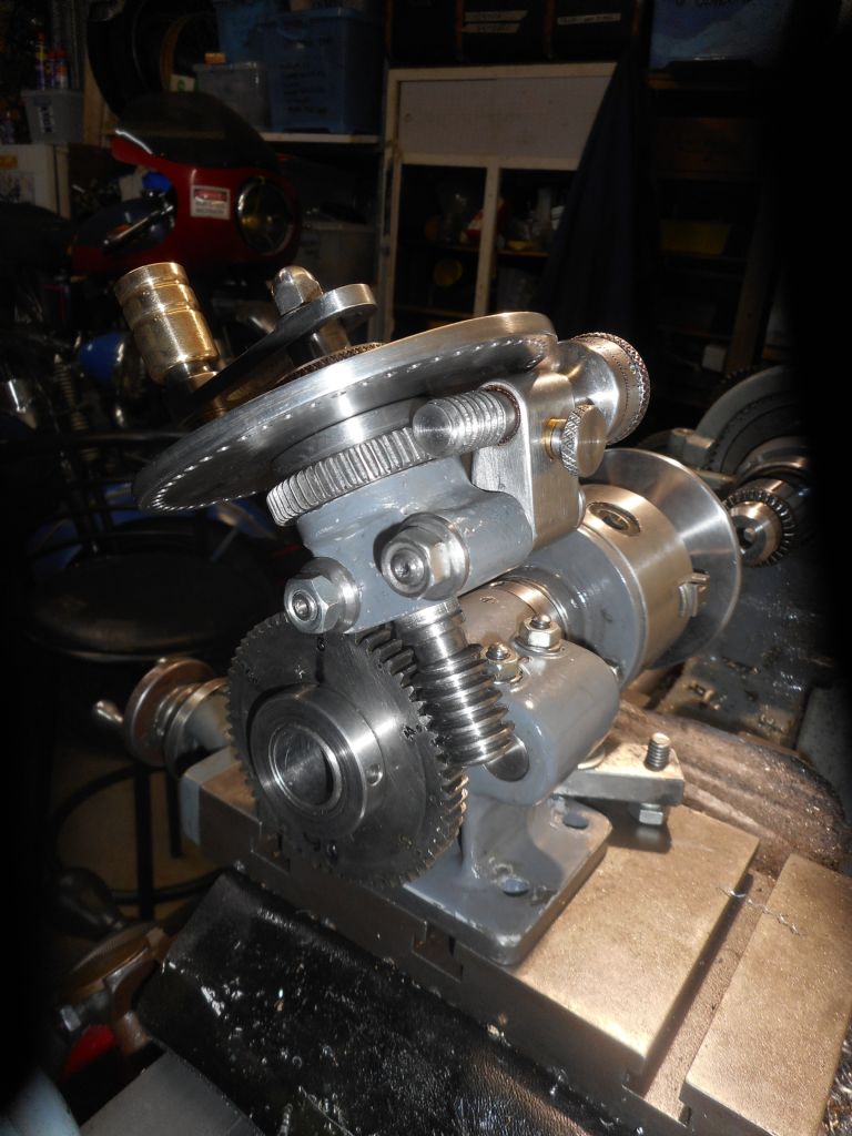
                    I did this with great success on my fabricated Versatile Dividing Head. I used a straight-cut Myford 60T change gear as the main "worm wheel" and turned the worm teeth to a thinner than normal profile so the worm shaft could be twisted from its natural angled position to one straight in line with the Myford gear. Yes, it gives point contact, which is sufficient for positioning only purposes like dividing heads and thread indicators.

                    I can't claim the idea as my own. Martin Cleeve in his book Screwcutting in the Lathe outlines the thinning of teeth/thread to achieve straight alignment between worm and and straight-cut gear.

                    The pic below shows the straight-cut main gear with the worm mounted square to its axis, using the above method. The smaller "worm-wheel" was made at home with the teeth straight but skewed at the helix angle of the worm, just for the sake of it. When cutting the gear it was no extra bother to kick the vertical slide around to the helix angle and cut the teeth skewed.

                    dscn2965.jpg

                    So for a thread chaser dial, proper helical gears would be overkill in most cases. Skewed would work perfectly and straight could be made to work perfectly also, if you cut your own gear with thinner than normal teeth.

                    Neil has a nice article on file on this very topic so I expect it will appear in MEW one day with all the gory details.


                    Edited By Hopper on 10/08/2018 00:56:13

                    Edited By Hopper on 10/08/2018 00:59:41

                    #366584
                    Neil Wyatt
                    Moderator
                      @neilwyatt
                      Posted by Hopper on 10/08/2018 00:49:01:

                      Neil has a nice article on file on this very topic so I expect it will appear in MEW one day with all the gory details.

                      Indeed, but still a few other longer articles ahead of it in the queue.

                      #366638
                      Howard Lewis
                      Participant
                        @howardlewis46836

                        Lots know the theoretically correct way to mesh the gear with the Leadscrew.

                        But bear in mind that the gear on a T D I is only required to transmit enough torque to overcome the friction in the bearings of its shaft.

                        So, I would imagine that a theoretically incorrect spur gear, probably only making point contact, would be quite adequate for the task, as long as the tooth form conformed fairly closely to that of the thread on the Leadscrew..

                        "C'est brusque, mais ca marche"; as someone said of the "crash" gearbox.

                        Howard

                      Viewing 10 posts - 1 through 10 (of 10 total)
                      • Please log in to reply to this topic. Registering is free and easy using the links on the menu at the top of this page.

                      Advert

                      Latest Replies

                      Viewing 25 topics - 1 through 25 (of 25 total)
                      Viewing 25 topics - 1 through 25 (of 25 total)

                      View full reply list.

                      Advert

                      Newsletter Sign-up