Sorry folks, I thought I'd been clear enough in my initial description, but the problem is the same as always without a proper proofreader.
I can visualise what I was saying, I've got the parts to which I was referring as well as a mental picture, but it's obviously not clear the way I worded the question(s)
Firstly, I've never suggested tapping anything from scratch, merely cleaning up a roughed out thread(s) I'd already cut in the lathe, to make sure it's not "drunken"; I'm quite happy cutting left hand internal threads, though it's not something I've had the need to do very often.
Oily, or Mr Rag if you prefer,  on my Clarkson, as you say, there is a left hand ½" BSF thread, which you use with appropriate spacers etc to fix the wheel, exactly in the manner you describe.
I've actually made several extended carriers, duplicating the main spindle, so I can have several different wheels ready mounted.
The little Herbert surface grinder works slightly differently; probably more akin to other surface grinders, and the wheel is held in a demountable carrier.
It's only got a 6" wheel capacity, and the normal bore size seems to be either 1¼" or 32mm, depending on the wheel material and source. Unfortunately, some vendors seem to think the two sizes are interchangeable, and don't always supply what's expected/advertised.
Keith, many thanks for your link, most useful.
My intention is to make a number of carriers, so I don't have to re-balance the wheel/carrier combination every time I change wheels. There will be more than one design, but for the time being I'll more or less duplicate the one which came with the machine in both 1¼" and 32mm.

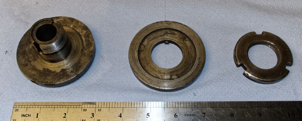
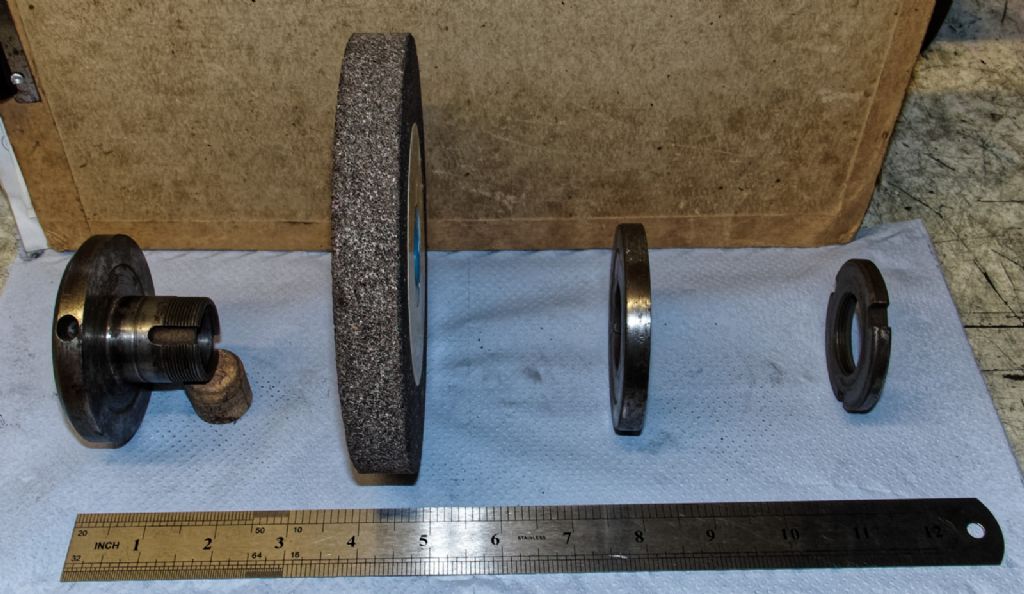
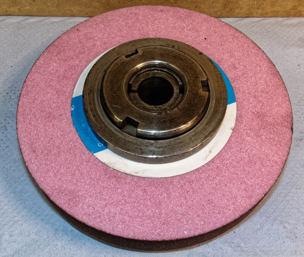
Here's the disassembled wheel carrier;
Left to Right; wheel carrier/rear flange – front flange – securing ring/nut

Assembly order;
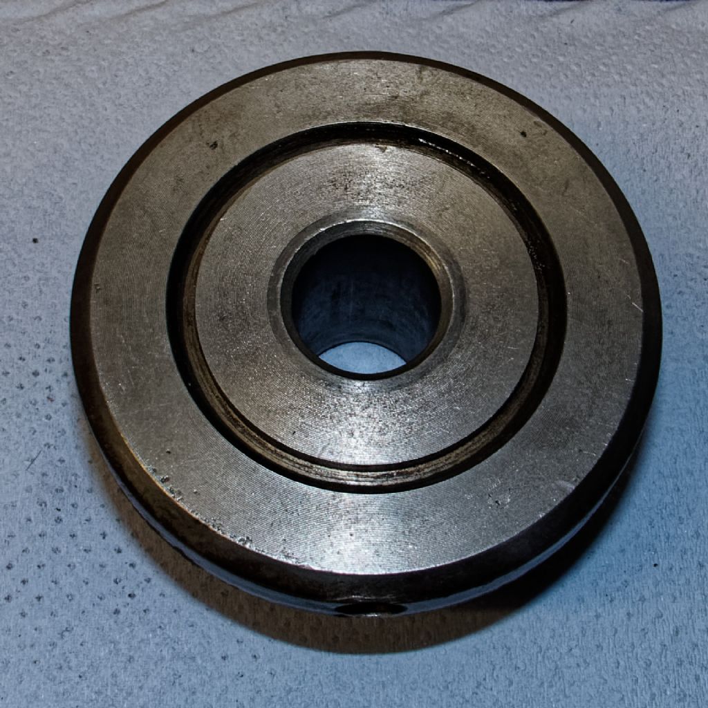
The "Top Hat" on the left has a parallel section 1¼" to suit the bore of the wheel, the front flange/washer is keyed, and also has a different depth recess each side to accommodate either ½" or ¾" wheels.
The washer/flange is actually a very loose fit on the bore size; I don't know if it's original, intentional, or just poor engineering.
That said, I've found that by offsetting it slightly from central, I can use it for balancing the wheel; this design of carrier doesn't allow any other obvious method, and I'm not experienced enough, or comfortable doing it the old way with a masonry bit.
The right hand item holds everything together. I've actually made a spacer so I can use a ¼" thick wheel as well.
The thread twixt left and right parts is undersize from 1¼" and actually measures at 1.22" @ 22tpi
This is the left hand thread I'll be cutting on both parts, as many times as the number of carriers of this style that I make.
The only reason for a tap was to smarten up and standardise the ID of the thread internal to the ring nut, so it's hardly essential, just time saving.

The rear of the top hat carrier also has a concentric ring cut into it, to act as a very basic labyrinth dust shield for the main spindle.
It has a through bore to suit the ¾" main spindle

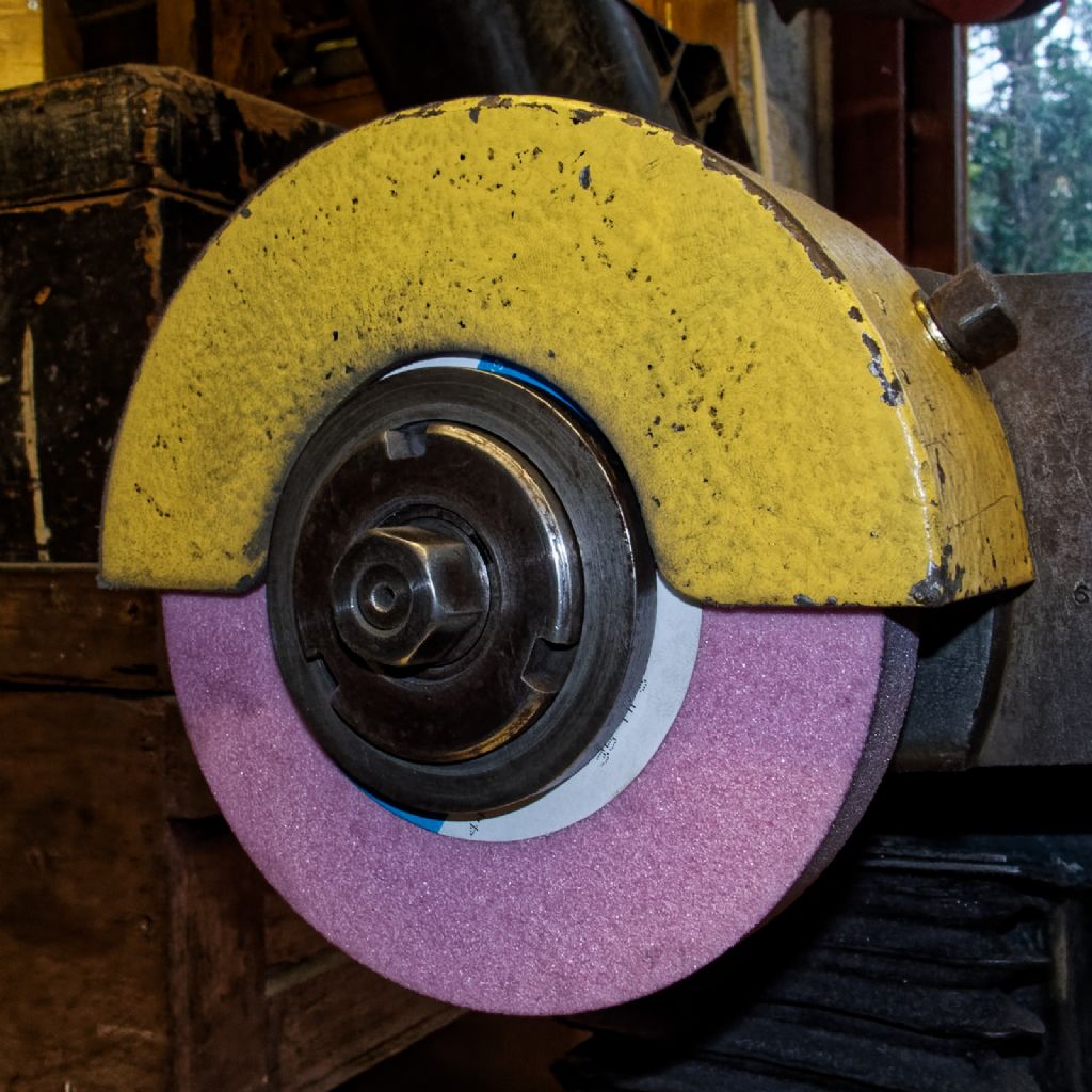
The parts assembled ready to fit to the spindle;

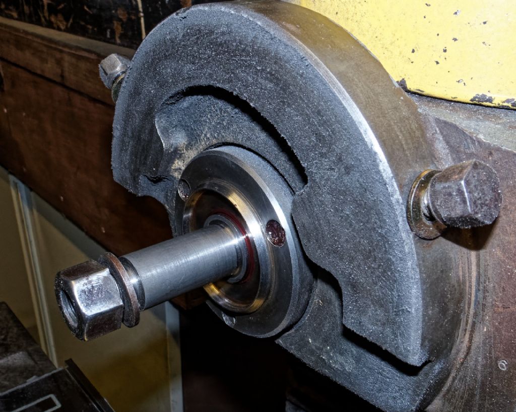
As you can see, the main spindle has a step at the end, and the assembled carrier/wheel is retained by a single ½" L/H BSW nut and plain washer. (annoying as I already have a L/H BSF tap from when I made the Clarkson adaptors)
You can also see the triangular annular ridge which forms the other half of the dust excluder, this is on a static part, and doesn't rotate with the spindle.

Cheers Bill
Edited By peak4 on 13/08/2020 21:19:04
 peak4.

