KERRY TYPE A.G. LATHE

Advert

KERRY TYPE A.G. LATHE

Home Forums Workshop Tools and Tooling KERRY TYPE A.G. LATHE

Viewing 25 posts - 1 through 25 (of 48 total)
  • Author
    Posts
  • #523265
    Steve Ambler 1
    Participant
      @steveambler1

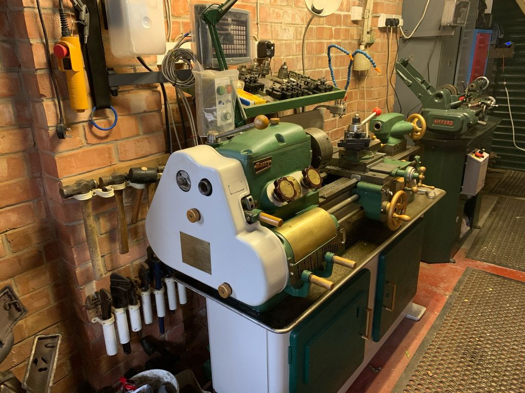
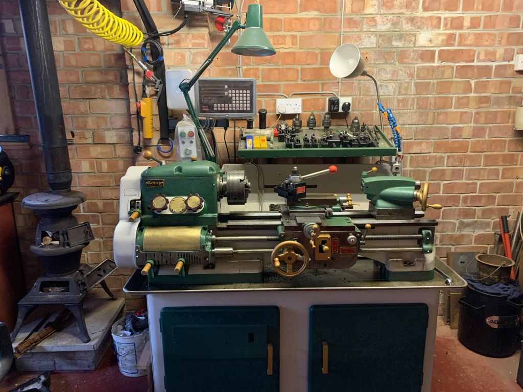
      ef494a9e-1abf-4bd1-b2b1-9dbac7720c47.jpeg8f7c0bcb-67d6-41f3-885b-45c1107254e4.jpeg4ca23f71-9099-4928-8b64-ab3b1c0407b6.jpegaf17f4c9-9842-4eed-808c-506bc0c65546.jpegI have over the last few years stripped down & refurbished my Kerry A.G. lathe 

      Ive also fitted a DRO & transwave phase converter as seen on photos

      I would like to fit a collet chuck & appreciate any advise on what collet chuck would fit my machine as I have no luck in finding a factory fit model

      I didn’t want to machine a backplate & fit a Chinese chuck if possible

      any advice would be appreciated

      I have included pictures of machine before & after


      Edited By Steve Ambler 1 on 28/01/2021 13:22:22

      Advert
      #20127
      Steve Ambler 1
      Participant
        @steveambler1

        Collet chuck advise

        #523276
        John Haine
        Participant
          @johnhaine32865

          That looks nice! The first question is, what is the nose fitting? And do you want to 5C type collets of (probably) ER40 (given the size of the lathe)?

          #523317
          Howard Lewis
          Participant
            @howardlewis46836

            Collet chucks are good, but will limit the diameter, and type of work, that you can hold.

            Also, for any non circular work, you are very likely to need conventional chucks.

            You can't grip the inside, of tubular work or a bore, with a collet chuck. You can with reversed jaws in a 3 or 4 jaw chuck.

            3 Jaw for hexagonal or large diameter round materials, and a 4 jaw independent for square, or irregularly shaped work (Or if you ever want to drill or bore a workp[iece off centre &nbsp

            Some work can only be done by holding the work in a 4 jaw, with one or more jaws reversed.

            Making up and machining backplates will make you more familiar with the machine, and at the same time extend the range of work for which it can be used.

            Howard

            #523321
            Steve Ambler 1
            Participant
              @steveambler1

              Glad you like it

              the spindle nose is 2” 4TPI

              I was thinking of er 32 as I have the collets

              but I do like the 5c system but I am flexible

              thanks for your reply

              regards. Steve

              #523326
              not done it yet
              Participant
                @notdoneityet

                Are you wanting a draw-bar chuck or a screw on chuck? Former is easier, if you do not require a sleeve to reduce from 4 1/2 MT. If the latter, do provide the nose thread – and no, you will likely need to buy or make a back plate if it is not a common size.

                Most of the details are on the lathesdotco site, but I was not going to trawl through it all, when you can do it once for the whole readership to see.

                Edited By not done it yet on 28/01/2021 16:28:28

                #523330
                John Haine
                Participant
                  @johnhaine32865

                  Wow! That's a big thread! Look at Arc Eurotrade's site – they do both 5C and ER collet chucks to fit a backplate, you would need to make that (but I'm sure the lathe could eat it for breakfast). I guess they both will procure their chucks from China but there are probably UK made ones at a premium.

                  Or you could make a chuck from a steel billet – EN8? Bore out to clear the maximum material size and cut and thread a recess to fit the nose register at the same setting. Then reverse and screw onto the nose, bore out for ER collet taper, turn down the outside to threading depth for the nut, and you're done.  Of course you ahve the collets and also I assume a closing not, but a ball bearing closer would be nice.

                  Edited By John Haine on 28/01/2021 16:35:52

                  #523347
                  David Marks 2
                  Participant
                    @davidmarks2

                    I worked in apprentice training for a long time and we had a bank of 6 Kerry AG lathes and the collets were the drawbar type. I cannot recall the female taper in the headstock spindle but possibly 4 Morse. I would think that other machines of different manufacture would have used the same system so there is equipment around that can be adapted.

                    #532524
                    Green Techie
                    Participant
                      @greentechie

                      I also recently purchased a Kerry A.G. Mk3 and am also looking at a collet chuck, the EC type. I know someone with a larger lathe who is very happy with their EC collets.

                      My lathe came with the 127t and 32t change gears fitted, but no other gears. So I can only cut some of the metric threads and no imperial threads.

                      Did yours come with the full set and if not have you found anywhere to supply them? I have read they are 18DP 20PA, is that correct?

                      #532569
                      Howard Lewis
                      Participant
                        @howardlewis46836

                        The Norton gearbox should allow you to cut a variety of thread pitches.

                        If the Leadscrew is Imperial, the 127T gear will allow you to cut, as you say, Metric pitches.

                        If the Leadscrew is Metric, the 32T should allow you to cut more Metric pitches.

                        My lathe (not a Kerry ) has a Metric Leadscrew, and the normal drive gear is 40T, changing this to a 32T allows more pitches to be cut.

                        You have two changewheels, so measuring these and counting the teeth will allow you calculate the DP of the gears.

                        Finding the PA may be a little more difficult, but I believe that data allowing this to be measured and calculated have appeared on the Forum in days gone by.

                        If you cannot find the extra wheels that you need, armed with the dimensions, bore and thickness, and the results of your calculations, it should be possible to cut the  required gears.  With a Norton box, you should not need many.

                        Study the Lathes UK site on Kerry lathes.  You may find a lot of what you want there. 

                        Howard

                        Edited By Howard Lewis on 08/03/2021 13:52:13

                        #532573
                        Howard Lewis
                        Participant
                          @howardlewis46836

                          Looking at the Lathes UK site, it seems that earlier machines had 16 DP, 14.5 PA gears but that later ones used 18 DP 20 PA

                          So measure your two gears, and count the teeth, in that way you can calculate DP and the PA will follow from what you find.

                          The site says that by changing three changewheels a range of metric pitches could be cut.

                          It is a site well worth studying

                          Howard

                          #532670
                          Green Techie
                          Participant
                            @greentechie

                            Thank you Howard, I had looked at the lathes website and even purchased their set of manuals for the Kerry. However I had not measured my gears, and can now report the the DP for the two gears I have comes out at 18.1 and 18.2, so I assume that means they are the 18DP 20PA type.

                            The gears I am missing are the 60T, which with my 32T lets me cut all the imperial threads the lathe supports and the 48T and 56T needed for the rest of the supported metric threads.

                            By the way, I did try looking at draw bar collets, as meantioned by David. But my lathe didn't come with the 4.5MT to 3MT adapter that the lathe would have been originally supplied with (according to lathes.co.uk), so that option seems unavailable. I would love to find one, but they seem very rare. Strangely the lathe came with a 4MT dead centre, which fits neither the head or tail stock!

                            #532812
                            Howard Lewis
                            Participant
                              @howardlewis46836

                              So; a 60T 18 DP gear should be 3.444444" OD (3.444 should suffice )

                              A 48T should be 2.778" OD and a 56T should be 3.222" OD if you want to start turning blanks to cut the missing gears.

                              The other dimensions can be taken from your 32T or 127T gears.

                              4.5MT sleeves and centres are likely to be a bit hard to find. Souinds like you will have to start doing some taper turning. If you could find just one 4.5MT centre or sleve, it would make setting bover thebTop slide easier. Otherwise you will need to clock the mandrel and set over until you can get the clock to remain at Zero whether it is at the inner or end of the taper. Then you can start making your own cntres and sleeves, without altering anything.

                              Personally, I would do all the external turning first before doing the 60 degree for the centres.

                              Being lazy, once satisfied that my all polished tapers were a good (Blued ) fit in the Mandrel, I would buy and use a 3 MT reamer for the internal taper in any sleeves.

                              HTH

                              Howard

                              #533145
                              Green Techie
                              Participant
                                @greentechie

                                Thanks again Howard. I have read your reply several times, but being a newbie there's a lot to process!

                                I don't have the equipment to cut my own gears. Do you think it would be cheaper to buy what's needed than to have gears made? If so it would be useful to have. Looks like it would cost about £300-£500 to get them made.

                                Are you saying that if I had a 4.5MT sleeve or centre I could use it to align with the tailstock, or use it to turn between centres?

                                When you talk about clocking the mandrel are you talking about using a dial gauge along the length of the taper?

                                I didn't know about about MT reamers, so that's a good tip!

                                #533253
                                Howard Lewis
                                Participant
                                  @howardlewis46836

                                  Hi GT!

                                  It may be worth looking at someone like Davall Gears, HPC Gears, Reliance Gears, etc, to see if they have anything in their standard offerings.

                                  The gears could be costly, but where needs must and all that!

                                  Also it may be that they will need modifying to suit; by thinning the boss, or boring or bushing the bore.

                                  All these operations are straightforward turning operations.

                                  But at the end you will have the gears that you need to make use of all the facilities of your lathe.

                                  Howard

                                  #534453
                                  Green Techie
                                  Participant
                                    @greentechie

                                    Hi Howard,

                                    Thanks for the suggestions. I've done some more research on this and had some replies and quotes.

                                    I can buy standard spur gears from HPC, which match the required DP and PA.

                                    The boss would need thinning and the bore enlarging and I would also need to cut a 1/4" keyway.

                                    There is a choice of "Standard duty" (Steel 214M15/045M10) or "Heavy duty steel" (817M40 (En24) or 655M13 (En36)).

                                    Do you have any thoughts on pros/cons between Standard and Heavy duty? It looks like I would need carbide tooling for the heavy duty gears.

                                    My biggest obstacle is that I don't currently have a way to broach the keyways.

                                    It would be expensive to get completed gears from HPC but I can get EN8 made to size (with the keyway) cheaper elsewhere.

                                    #534463
                                    Clive Foster
                                    Participant
                                      @clivefoster55965

                                      Choose standard or heavy duty gears for whichever is the closest match in face width. As Howard says you may need to purchase one with a boss and thin that down to get the alignment right.

                                      The duty isn't heavy so whichever fits best will do. I used standard duty PG style ones for my Smart & Brown 1024 of similar capacity but rather heavier than yours. Smaller gears too, 20 dp, but standard duty is ampley strong enough. Heay duty gears machine justf ine with sharp HSS on the S & B.

                                      Keyways can easily be accurately filed with care or planed out on the lathe itself using a tool bit pointing sideways. Best to start with a drill of slightly smaller diameter than the key width to move most of the material first. Plug the hole before drilling if the drill will overlap the standard bore.

                                      When I did mine for the S & B I drilled the hole first, bored out the centre bore to size, rough filed nearly right and finished off dead to size by planing. Hardest part is resetting the gear in the chuck just so for planing. Mine fitted the key just as well as the standard factory ones.

                                      I suggest practice on some scrap first. Three goes should nail the technique.

                                      For cutting a taper sleeve set things up using the back side of the spindle taper then cut the sleeve thin end outwards. Make it overlenght and cut down as needed when finished.

                                      Clive

                                      #534466
                                      Tony Ray
                                      Participant
                                        @tonyray65007

                                        Hi,

                                        I don’t think you don’t need to spend that amount of money on change wheels

                                        **LINK**

                                        I’m sure this seller can make you what you need. Alternatively If you have access to a 3D printer you can print them, I have been experimenting in making them in 1.5 mod with the 6 spline centre as per the eBay listing, you may need to fettle the key way with a needle file. Many lathes use plastic/ tufnol gears.

                                        Tony

                                        #534469
                                        Green Techie
                                        Participant
                                          @greentechie

                                          Hi Clive, Tony

                                          Thank you both.

                                          Clive: I'm just looking up the differences you mention in the gear sizes between standard/heavy and thank you for the advice on cutting keyways. I'd like to try cutting the taper, but does the method you describe require turning between centres? As I don't have a 4.5MT centre. I've looked on YouTube but people either seem to be using centres or taper turning tools/jigs/motors.

                                          Tony: I do have a 3D printer, although I'm not sure it's precise enough for accurate gears. Perhaps if I try setting the bed level more accurately I could try it. I have actually already been in touch with the seller you mention, but he can only cut 14.5PA teeth and I need 20PA. I did make some recommendations on sources of the correct cutters but have not heard back.

                                          #534509
                                          Tony Ray
                                          Participant
                                            @tonyray65007

                                            Just to clarify you gears do not need to be ‘accurate’ i.e. precision ground to fine tolerances, all they need to is be able to run together. By that I mean all gears in the set must be able to be meshed with each other with no binding and not too much backlash. The purpose of the gear is simply to transfer motion from one to another at the desired ratio and be strong enough to transfer the power. In a 15 T to 30T gear train the ratio is the same whether the gears are precision ground or 3D printed. When cutting a thread that is not a multiple of the lead screw the closeness of the gear ratio to what is theoretically required is a factor. The pitch accuracy of the screw being cut is determined by the lead screw accuracy and the size of the error in the gear train ratio. Backlash in the gear train and lead screw is inevitable but the screw cutting process allows for it; the cut is always taken in the same direction and the tool is always started a few threads distance beyond the work so that the backlash is taken up before the tool contacts the work.

                                            Yes bed levelling is important. Chep on the ‘tube has som excellent advice on this, another tip I used to take up a dip in my bed was to shim it with post it notes between the bed and the removable magnetic build plate. I also took some time to calibrate the extruder and I can get to about 0.2mm on finished parts.The 6 spline on the Harrison gears is finicky and I had to adjust the model until I got a good fit, now I have this sorted it’s just a case of dropping this element into each gear model. In your case a bore with a single key way can be achieved in many ways. It will be worth increasing the fill density around the bore and the teeth. If you need further help on this please ask.

                                            I highly recommend Ivan Law and Martin Cleve’s books on gear and screw cutting respectively.

                                            #534538
                                            Michael Gilligan
                                            Participant
                                              @michaelgilligan61133
                                              Posted by Tony Ray on 18/03/2021 07:56:41:

                                              Just to clarify you gears do not need to be ‘accurate’ i.e. precision ground to fine tolerances, all they need to is be able to run together. By that I mean all gears in the set must be able to be meshed with each other with no binding and not too much backlash. The purpose of the gear is simply to transfer motion from one to another at the desired ratio and be strong enough to transfer the power. In a 15 T to 30T gear train the ratio is the same whether the gears are precision ground or 3D printed. […]

                                              .

                                              Whilst I fully accept the validity of that statement at a routine practical level, Tony … it cannot be the full story.

                                              If the velocity ratio of the gear engagement fluctuates; then even a ‘perfect’ lead-screw will effectively vary in pitch, and the effect must be carried through to the finished item as periodic errors.

                                              Totally irrelevant to most users, of course … just interesting.

                                              To be clear … “In a 15 T to 30T gear train the overall ratio is the same whether the gears are precision ground or 3D printed; but the variations in instantaneous velocity ratio may differ.

                                              MichaelG.

                                              #534540
                                              Howard Lewis
                                              Participant
                                                @howardlewis46836

                                                As already said, the gears do not to be nitrided, and precision ground.. The gear are required to transmit probably no more than one horse power and at low speeds.

                                                Myford gears are cast iron, and survive on 1940s vintage machines, Drummond gears will be much older

                                                Min lathes use plastic moulding for gears since the motor power, is less than one horsepower.

                                                Almost all the gears that need replacement on lathes use for hobby work, and in many industrial setting, are nnot worn, but broken by using backgear to lock the headstock whilst removing a screw on chuck.

                                                Standard steel will be quite adequate. For most purposes 3D printed gears would probably be adequate, unless you plant to cut 2" diameter 2 tpi threads in high grade steel or titanium.

                                                The chances are that, if you can't cut the gears, someone in a local M E club would be prepared to make what you want, in mild steel, either at not much more than cost, or even for a donation to club funds.

                                                With a small drill and a 1/8" square file and some care, keyways can be made, without slottingb or broaching facilities.

                                                (To everyone's horror, no doubt, I once made a 1/8" square hole by drilling out most of them material and then finishing by driving a toolbit to and fro whilst held in the Tailstock! ) I have cut other keyways, using the slotting tool designed by the late Peter Robinson. So it can be done.

                                                Howard

                                                #534557
                                                Clive Foster
                                                Participant
                                                  @clivefoster55965

                                                  Green Techicie

                                                  No need to turn between centres when replicating the headstock internal taper.

                                                  Once the tool travel is lined up with the back wall of the headstock taper just put a suitable length of round bar in the chuck and turn the taper. Sharp tool finishing with light cuts and all will be fine. Maybe rough out first into steps with another tool to save the real sharp one for final finishing.

                                                  Put it in the headstock for doing the inside to whatever is needed. For MT tapers best to make closest job you can with the lathe then finish off with a reamer.

                                                  It has been argued that once set up its worth making a "few" blanks ready for other uses.

                                                  Almost a trivial job with a taper turning attachment so making extras is hardly worth it but if doing with the top slide setting up is enough of a pain to be worth getting ahead of the game.

                                                  Getting the topslide set just so is harder, best way is to come up with temporary bolt on bracket to take a pusher screw. Two opposed screws would be ideal but more work. Mk3 Kerry AG lathes have a T slot in the cross slide which makes bolting something on easier, not sure about the older ones. If you anticipate doing anything move than very occasional taper turning using the top slide its worth making up a "screw pusher thing".

                                                  I think your reference to working between centres comes mostly to the normal practice of mounting a reference taper between centres when doing mores tapers with top slide or taper turning unit. You can do the job between centres, or in a collet, but holding in the chuck is fine as the actual work will be turned true despite any chuck errors. Between centres is easier if working towards the small end, chuck gets in the way rather. but normally there is never a reason to go that way.

                                                  Clive

                                                  #534569
                                                  Hopper
                                                  Participant
                                                    @hopper
                                                    Posted by Michael Gilligan on 18/03/2021 09:32:28:

                                                    If the velocity ratio of the gear engagement fluctuates; then even a ‘perfect’ lead-screw will effectively vary in pitch, and the effect must be carried through to the finished item as periodic errors.

                                                    Totally irrelevant to most users, of course … just interesting.

                                                    Very much so. (Both the irrelevance and the interest). As you know, math is not my thing (being an English Lit graduate and all), but I am thinking that if we take a 4" diameter change gear, with a circumference of just over 12", each one thou of deviation on a tooth profile is an error of (very roughly) 1 in 12,000.

                                                    But that is only in the radial positioning of the gear and the attached leadscrew shaft. The position of the halfnut and thus the carriage and attached cutting tool is determined by the, say, 8tpi leadscrew thread with a pitch of .125" .

                                                    So our one thou deviation from true tooth form becomes an error of 1/12,000th of .125" of carriage position. Which, I think but please check this, comes out to about 0.00001 "

                                                    So each one thou of mispositioning or misprofiling of a gear tooth would result in a screwcutting pitch error of one hundredth of a thou.

                                                    And that is if the error is on the final gear on the leadscrew itself. Error further up the gear train would be reduced by the reduction gearing.

                                                    So even if the total of misplaced gear teeth through the whole train totalled a phenomenal 100 thou, the effect on the screwcutting pitch would be only 1 thou. In reality, total misplacement of gear teeth is going to be a fraction of that. Maybe more like 10 thou max worst case secenario., giving a screwcutting pitch error of one tenth of a thou.

                                                    So still comes out to a way higher level of precision than the mass produced leadscrew on a hobby lathe or most toolroom lathes for that matter.

                                                    Not irrelevant to the current thread because it does demonstrate why there is no need for precision gears on a change gear drive train as queried above. Any old rough gears will do the job really. And the power they are transmitting is negligible. The lathe motor might be 1hp but the force needed to turn a leadscrew can be provided by two fingers on a leadscrew handwheel so is a fraction of that. Hence, change gears can be made out of aluminium or delrin and will probably outlast most of us.

                                                    Just a thought.

                                                    #534571
                                                    Howard Lewis
                                                    Participant
                                                      @howardlewis46836

                                                      Somewhere in my Apprentice Training Notes, I have the formula for calculating tailstock offset to turn a taper.

                                                      In 60 years have NEVER needed to use it.

                                                      If anyone wants it I'll dig it out, 

                                                      Found it! Will try to place the scan of the illustration on my Album

                                                      Instructions below. (For Offsetting Tailstock TOWARDS Operator.  Reverse procedure if offsetting AWAY )

                                                      1 ) Align Tailstock. (Mount Alignment mandrel  between centres and fit DTI on toolpost )

                                                      2) Insert workpiece between centres.

                                                      3 ) Calculate Tailstock set over.  

                                                      (Total length of work x taper per inch ) / 2

                                                      4&nbsp Apply DTI to parallel section of Tailstock. To eliminate backlash, exceed Zero position and set to Zero on return movement.  At this stage Zero Cross Slide dial.

                                                      5 ) Wind DTI away from work an amount equal to the dimension found by the formula.

                                                      6 ) Slacken Tailstock mounting bolts and adjust Tailstock towards DTI until Zero is reached.   

                                                      7 ) Resecure tailstock

                                                      Howard

                                                      Edited By Howard Lewis on 18/03/2021 11:23:35

                                                    Viewing 25 posts - 1 through 25 (of 48 total)
                                                    • Please log in to reply to this topic. Registering is free and easy using the links on the menu at the top of this page.

                                                    Advert

                                                    Latest Replies

                                                    Viewing 25 topics - 1 through 25 (of 25 total)
                                                    Viewing 25 topics - 1 through 25 (of 25 total)

                                                    View full reply list.

                                                    Advert

                                                    Newsletter Sign-up