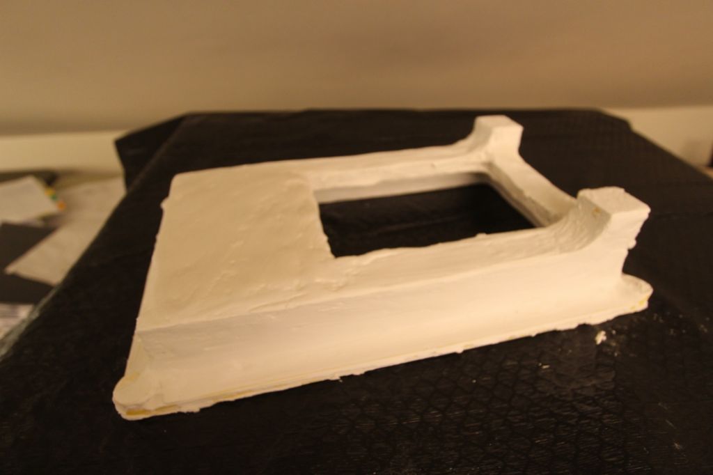
Jumbo Dake

Advert

Jumbo Dake

Viewing 17 posts - 1 through 17 (of 17 total)
  • Author
    Posts
  • #31251
    PatJ
    Participant
      @patj87806

      Casting a jumbo Dake in gray iron

      Advert
      #399607
      PatJ
      Participant
        @patj87806

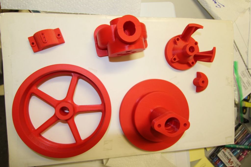
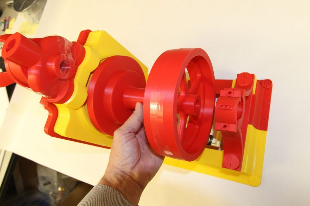
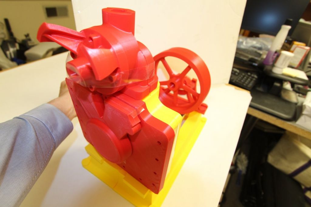
        I bought a Prusa MK3 printer the other day, and decided to print out the patterns for a jumbo-sized Dake engine as a trial run.

        So far I am quite impressed with the little printer, and it has basically been running 24/7 for over a week without any problems.

        This will be on the large size for a model engine, but I like to straddle the line (or cross it) between models and small workshop engines.

        My eyesight is not good these days, so this is basically an engine version of a large print book for the visually impaired.

        The engine will be poured in gray iron using my backyard oil-fired furnace.

        I will probably pour permanent patterns in 356 aluminum first, since the plastic tends to get brittle over time, and some of the printed patterns are pieced together from multiple printed pieces.


        Edited By PatJ on 10/03/2019 17:07:01

        #399608
        PatJ
        Participant
          @patj87806

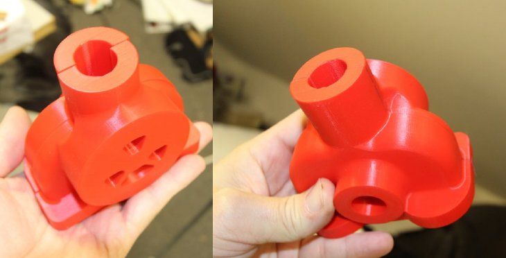
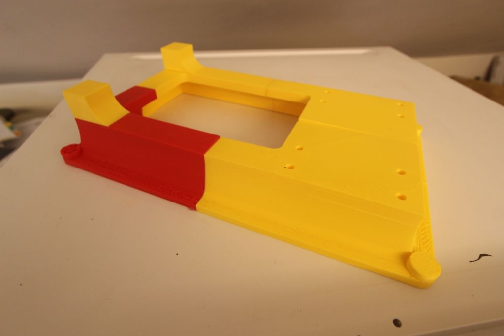
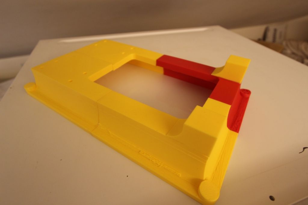
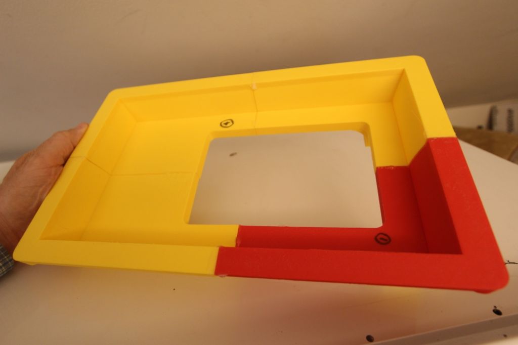
          Here are a few photos of the printed patterns so far.

          The surfaces inline with the pattern pull have a minimum of 5 degrees draft.

          Bearings will be poured babbitt.

          rimg_2947.jpg


          rimg_3082.jpg

          rimg_3088.jpg

          rimg_3089.jpg

          trim-comparision.jpg

          Edited By PatJ on 10/03/2019 17:11:20

          #399609
          PatJ
          Participant
            @patj87806

            This is my furnace in action.

            The crucible lift is at 1:00.

            Edited By PatJ on 10/03/2019 17:10:35

            #604683
            PatJ
            Participant
              @patj87806

              It has been a while since I worked on this engine, and I have moved all of my videos to Vimeo, so the link above is no longer valid.

              Perhaps this new link will work:

              https://vimeo.com/user82094693

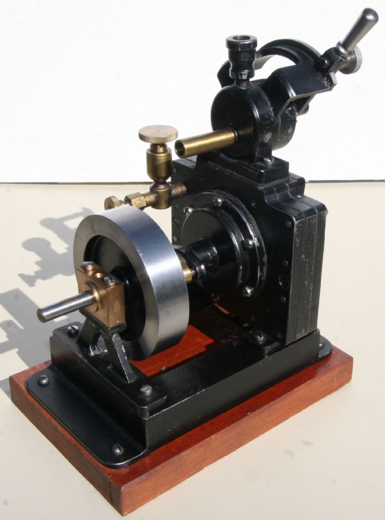
              The story behind this engine is that my Dad saw some information on a Dake engine in an old Audel's book in about 2000, and built a barstock version of a Dake (photo below).

              Dad was a free-lance builder, and never built any model engine in an exact fashion.

              Dad died in 2006, and so I was able to perserve about 18 of his engines, including his Dake.

              .


              dake-front.jpg

              Edited By PatJ on 07/07/2022 01:30:23

              #604684
              PatJ
              Participant
                @patj87806

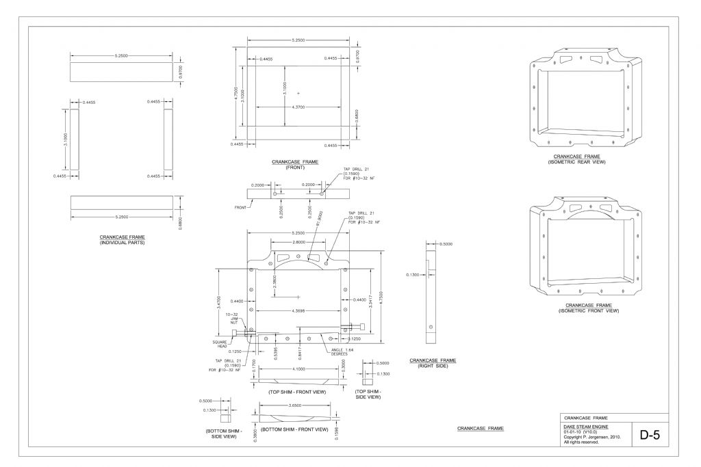
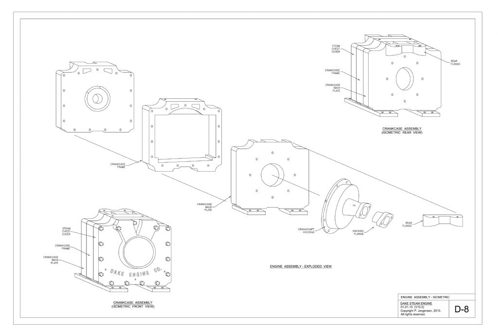
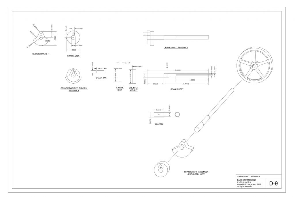
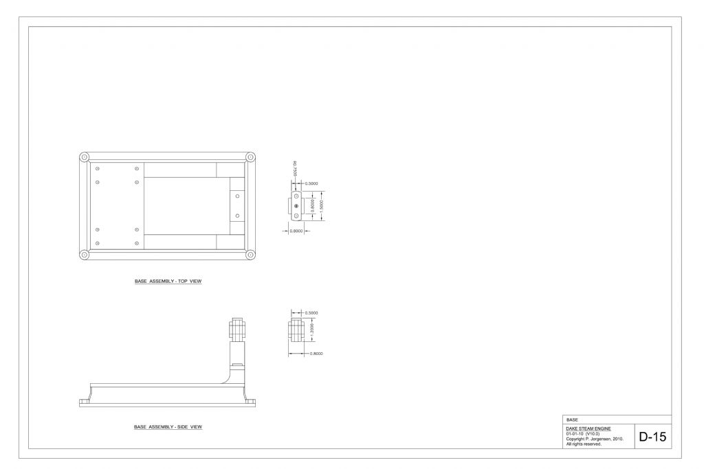
                I had visions of building a Dake one day, but I wanted a build that was more true to the original Dake design, so I studied the Audel's information, and drew a fairly exact scale Dake engine.

                I posted my Dake drawings on an old website in about 2011, and a fellow named Stu Hart saw them, and asked if he could build a Dake model from the drawings. I told him that one day I would build and perhaps publish a Dake myself, and so I told him he could use my drawings, but that he should morph his build into something a bit different, and not just outright copy my design.

                I have never seen the article, but I am told that Stu published the "Potty Dake" in Model Engineer.

                No doubt it was an excellent build, given the engines I have seen that Stu has built.

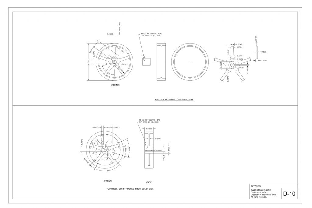
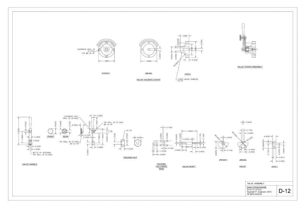
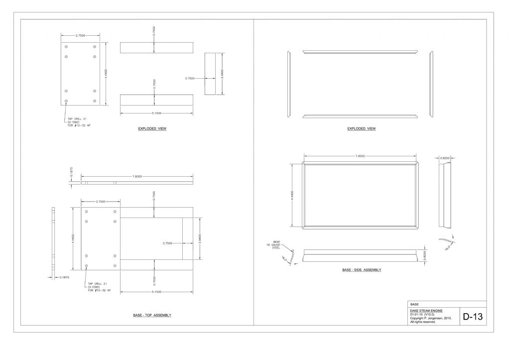
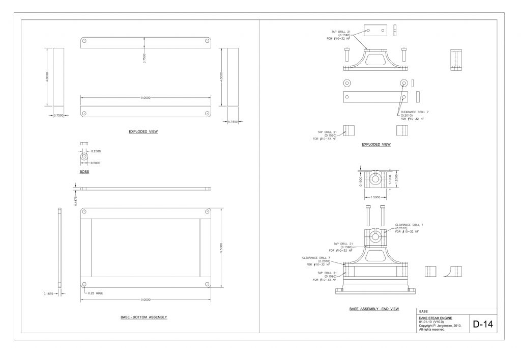
                Below are the drawings that Stu had, and these were the genesis for the Potty Dake build.

                These were my second atttempt to draw a steam engine, and at the time, I could only draw in 2D.

                Looking back on these drawings, they seem rather crude.

                The isometric views were hand-sketched in 2D autocad, and so are pretty rough.

                The geometry in these drawings I believe is valid though, and I paid close attention to that.

                This is a barstock build design, because at the time, I never dreamed I would learn how to cast engine parts.

                The format is large (ARCH-D which is 24"x36&quot.  These days I generally use an 11"x17" format, which is much easier to plot and handle in the shop.

                dake-cad-dwg-ver-11-page-01.jpg

                dake-cad-dwg-ver-11-page-02.jpg

                dake-cad-dwg-ver-11-page-03.jpg

                dake-cad-dwg-ver-11-page-04.jpg

                dake-cad-dwg-ver-11-page-05.jpg

                dake-cad-dwg-ver-11-page-06.jpg

                dake-cad-dwg-ver-11-page-07.jpg

                dake-cad-dwg-ver-11-page-08.jpg

                dake-cad-dwg-ver-11-page-09.jpg

                dake-cad-dwg-ver-11-page-10.jpg

                dake-cad-dwg-ver-11-page-11.jpg

                dake-cad-dwg-ver-11-page-12.jpg

                dake-cad-dwg-ver-11-page-13.jpg

                dake-cad-dwg-ver-11-page-14.jpg

                dake-cad-dwg-ver-11-page-15.jpg


                Edited By PatJ on 07/07/2022 02:09:16

                #604685
                PatJ
                Participant
                  @patj87806

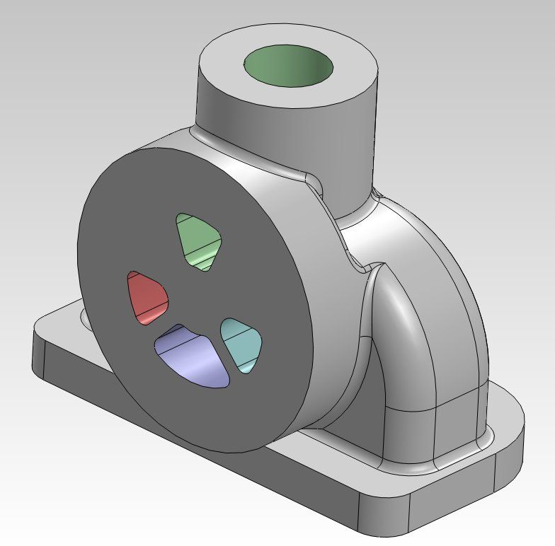
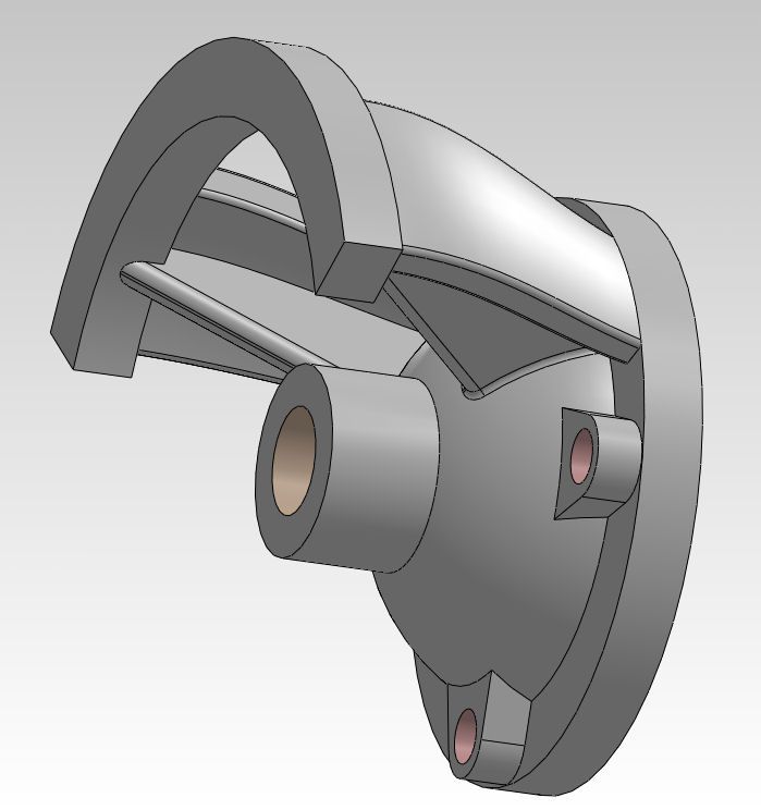
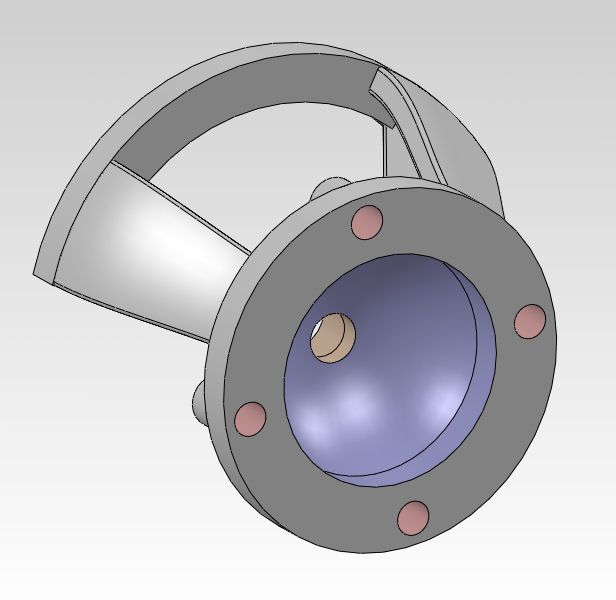
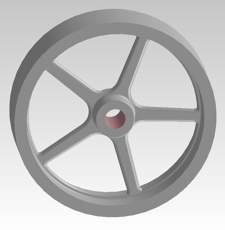
                  As time progressed, I realized that 2D CAD was a very poor design tool for engine work, and so I started to learn 3D modeling (Solidworks).

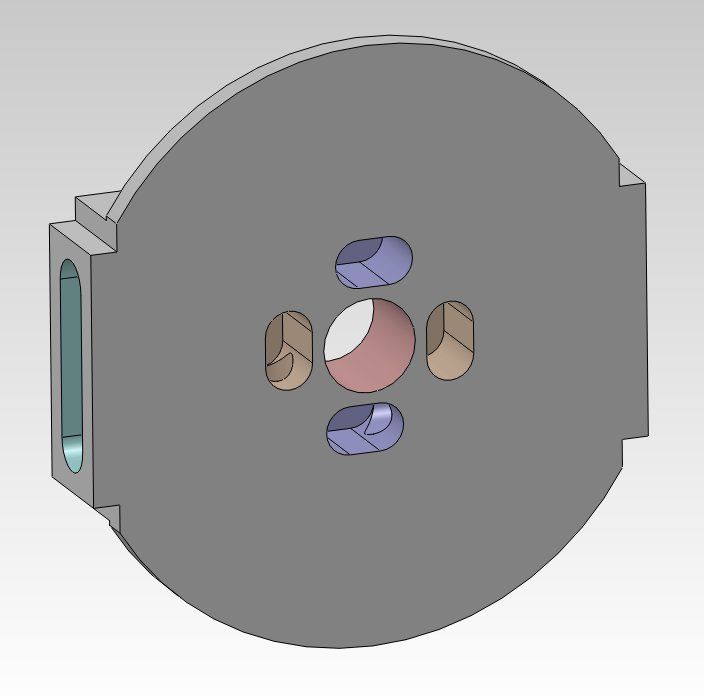
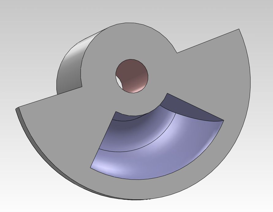
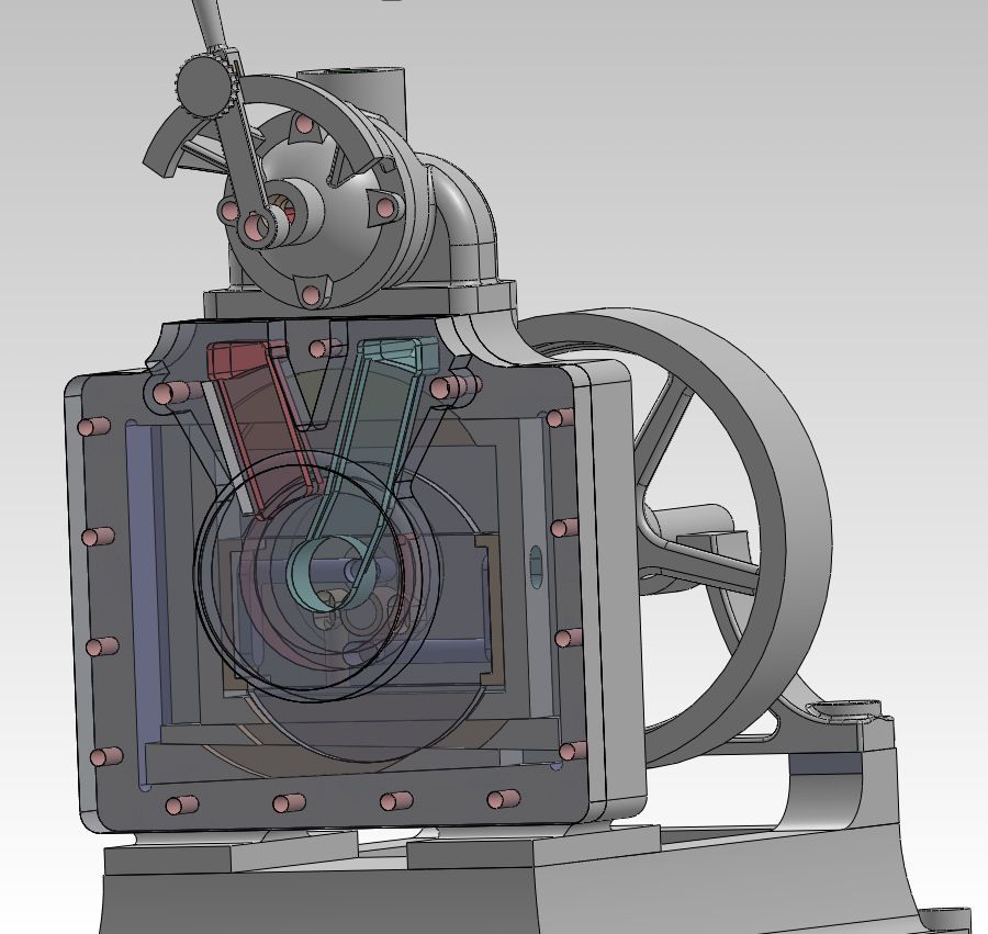
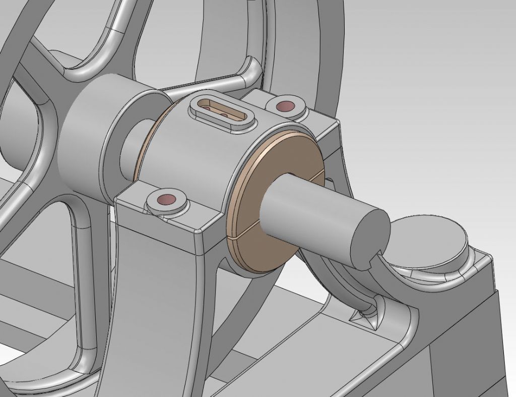
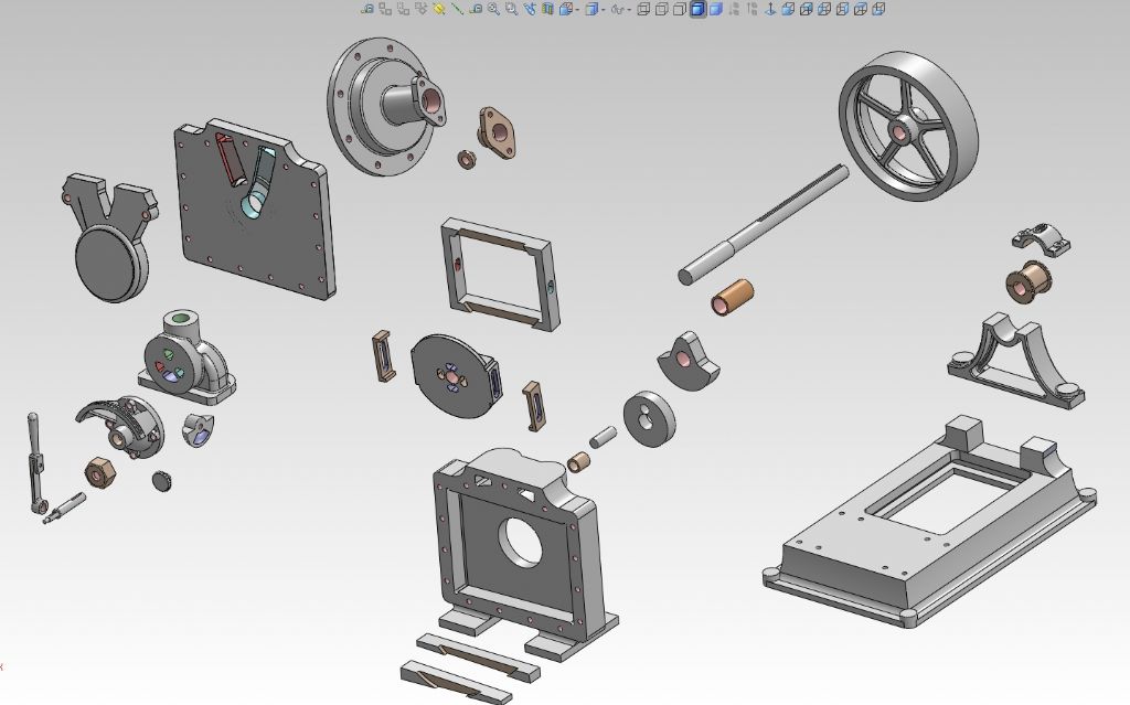
                  Since I had the Dake 2D drawings completed, I used them to create a Dake in 3D.

                  Here are a few screencaps.

                  dake-knob-02.jpg

                  dake-piston-01.jpg

                  dake-valve-01.jpg

                  dake-valve-02.jpg

                  dake-valve-body-03.jpg

                  dake-valve-body-07.jpg

                  dake-valve-cover-01.jpg

                  dake-valve-cover-03.jpg

                  dake-valve-04.jpg

                  dake-frame-05.jpg

                  dake-flywheel-01.jpg

                  dake-crank-assembly-01.jpg

                  dake-assembly-11.jpg

                  dake-assembly-12.jpg

                  image3.jpg

                  #604686
                  PatJ
                  Participant
                    @patj87806

                    So now that I have the casting thing down, I am dusting off the Dake 3D printed patterns, and I intend to start casting some engine parts.

                    Many of the parts will be fairly easy to mold.

                    I will probably touch up the 3D printed patterns, to reflect that this is no longer a barstock build (add a few fillets here and there).

                    The most complex shapes to mold will be the valve body and its multiple passages, and the crankcase cover with its multiple passages.

                    The remainder of this engine should mold up fairly easily.

                    The plan is to make these castings in gray iron, and I think I can accomplish that.

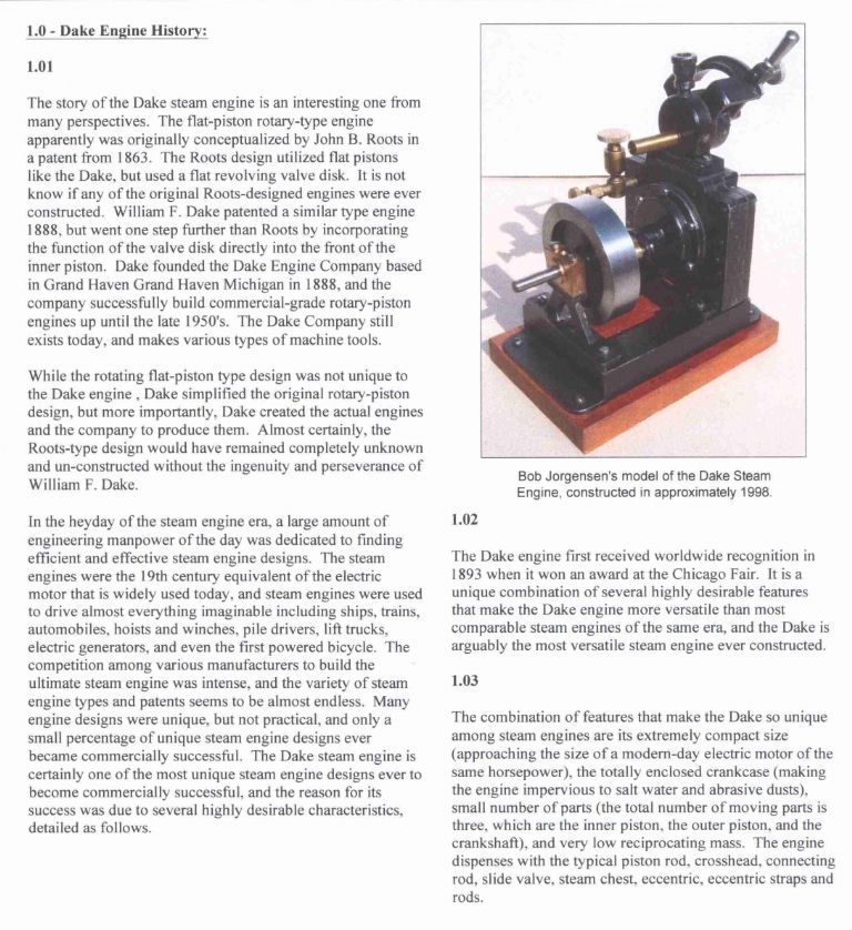
                    For those not familiar with the Dake, this design appears to have been an almost carbon copy of a Roots engine that was patented about 20 years earlier than Dake's patent.

                    Dake made some slight changes to the Roots engine (at least that is my speculation; Dake could have actually created an almost identical engine independently, but I sort of doubt that).

                    I am surprised that the patent office allowed Dake to patent an engine that was so close to the Roots design.

                    I have never seen any Roots engines like this design, but the Dake version was a very successfully manufactured engine, with quite a few of them sold commercially.

                    This is a two-cylinder engine, with no dead-centers.

                    The pistons are shaped like a piece of toast, ie: they are flat on two sides and roughly square in shape.

                    The inner piston rides inside of a hollowed out outer piston.

                    The design seems laughably impractical, and yet my Dad's Dake engine is an amazingly smooth running engine, with no appreciable vibration.

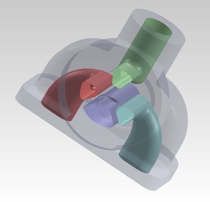
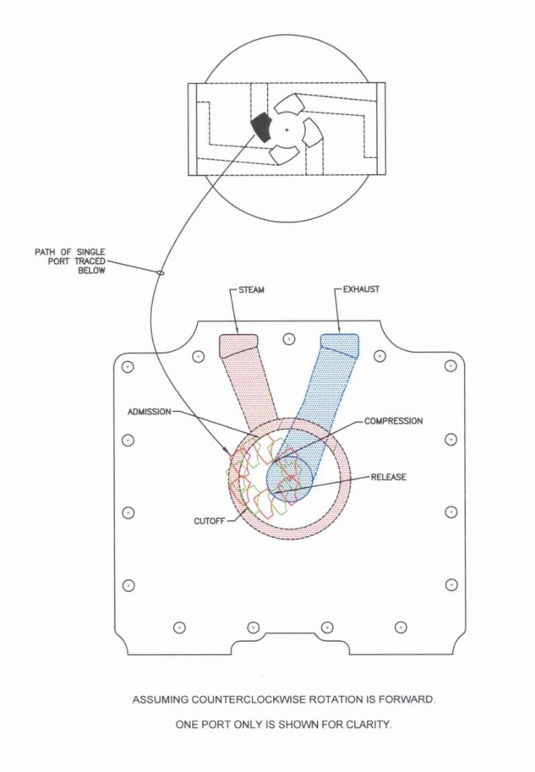
                    It took me quite a while to wrap my head around how all the passages work in this engine.

                    The center piston also acts as a slide valve, and the port faces are build into the crankcase housing.

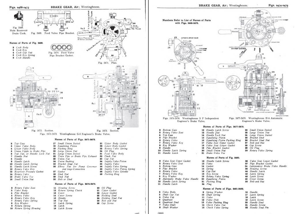
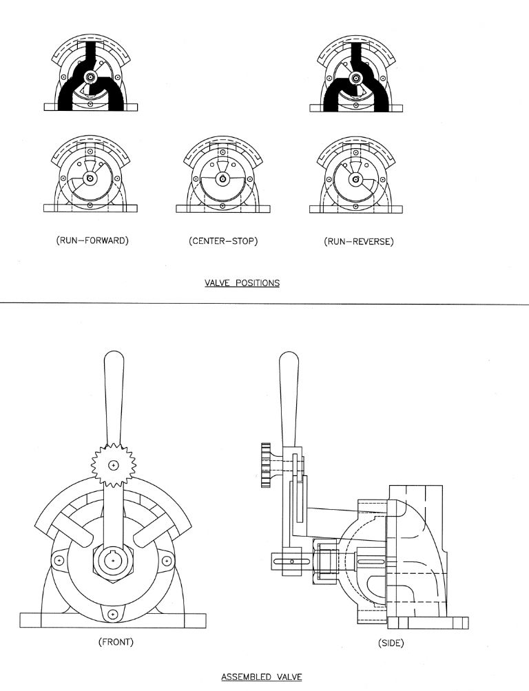
                    The valve body is for reversing the engine, and it works in a fashion very similar to a Westinhouse air brake valve, if you have ever seen one of those.

                    .

                    westinghouse-252-253.jpg

                    #604687
                    PatJ
                    Participant
                      @patj87806

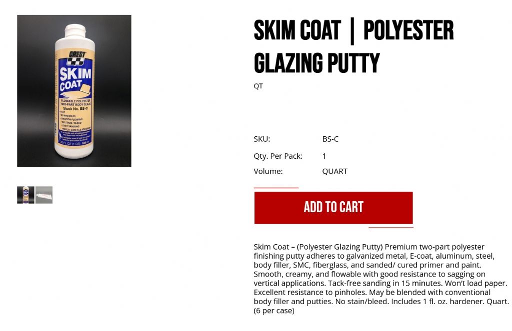
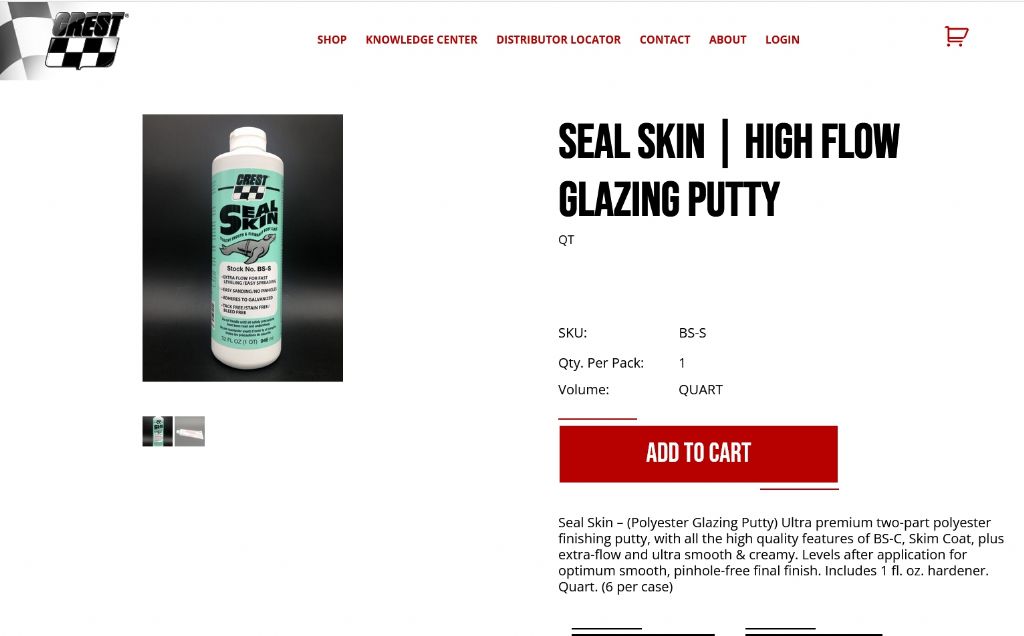
                      I ordered some auto body skim coat, in both the thicker putty for vertical surfaces, and the thinner self-leveling material for flat surfaces.

                      I have never used this material before, but the idea is to skim a very light coat of one or the other of these materials onto the Dake 3D printed patterns, in order to get a perfectly smooth (sanded) finish, with no lines in the surface.

                      I hope this material works.

                      image47.jpg

                      image48.jpg

                      #604688
                      PatJ
                      Participant
                        @patj87806

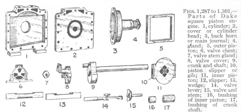
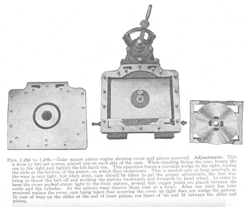
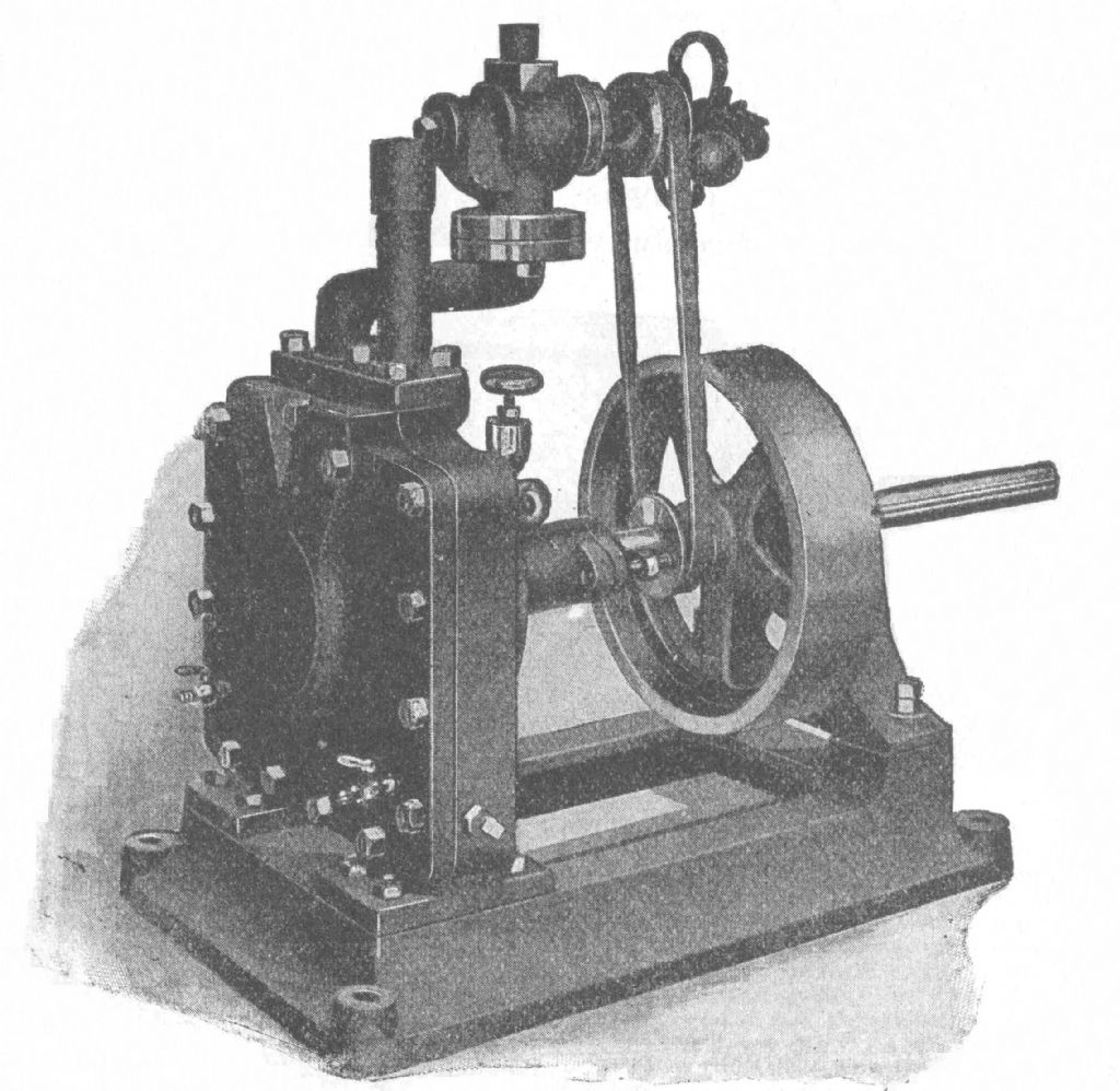
                        These cuts are from the Audel's book that my Dad used to make his Dake.

                        The Dake engine design varied over the years, and no two appear to be exactly alike.

                        Even in these cuts from the same article, the ports in the inner piston vary.

                        I have seen rounded ports in the inner piston too, along with more of a teardrop-shaped port.

                        I am not sure what is going on exactly in these cuts, since in the second cut, the ports at the top of the crankcase are 180 degrees out. The ports in the crankcase should be as shown in the first cut.

                        Some engines had reversing valves, and some did not.

                        Some had the reversing valve remote-mounted, so the engine could be operated by a valve at ground level, with the engine at the bottom of a mine shaft.

                        The tapered shims in the bottom of the crankcase allow the slack to be taken up on the outer piston.

                        Dake offered metal gaskets for the crankcase cover in increments of 0.001", so that the clearance between the pistons and cover could be adjusted.

                        The counterweight on the crankshaft offsets the weight of the center piston to some extent.

                        The last cut shows the engraving I used as a guide for which Dake model I wanted to mimic.

                        I added the reversing valve, since most Dake's seemed to have that feature, as shown in the second cut.

                        .

                        dake-audel-hi-res-02b.jpg


                        r-dake-audel-02a.jpg

                        magazine-dake-05.jpg

                        Edited By PatJ on 07/07/2022 02:52:52

                        #604689
                        Jon Lawes
                        Participant
                          @jonlawes51698

                          Utterly fascinating. Thank you.

                          #604694
                          Adrian Nicolson
                          Participant
                            @adriannicolson

                            Hi PatJ,

                            I agree with the sentiments made by Jon Lawes…and I certainly would, very much, like to know even more.

                            Please keep adding more content on both your progress…and the details of this fascinating Engine.

                            …I am a fan

                            Best Regards,

                            Adrian

                            #604721
                            SillyOldDuffer
                            Moderator
                              @sillyoldduffer

                              Woke up to find this breakfast treat! Dake engine, CAD and coffee – perfect.

                              smiley

                              Dave

                              #604780
                              PatJ
                              Participant
                                @patj87806

                                Thanks all. I must admit I had to take my Dad's Dake engine apart and study each piece in order to finally fully understand how this engine works.

                                Here is a writeup I made about the Dake in 2010.

                                I can't guarantee that everything in this writeup is 100% accurate, but it reflects my understanding of the Dake engine.

                                The inner piston is pinned to the crankshaft, and it can only move up and down within the outer piston.

                                Pressure applied to the outside of the inner piston can only move it either up or down.

                                The outer piston is constrained by the adjustable shims in the bottom of the crankcase, and it can only move side to side.

                                What gets confusing is the inner piston is also the valve, with 4 ports in it.

                                The valve face where steam is admitted and exhaust is released is the back of the crancase, which is the cover facing away from the crankshaft/flywheel side.

                                r0.jpg

                                r1.jpg

                                r2.jpg

                                r3.jpg

                                r4.jpg

                                r5.jpg

                                r6.jpg

                                Edited By PatJ on 07/07/2022 12:33:34

                                #604785
                                PatJ
                                Participant
                                  @patj87806

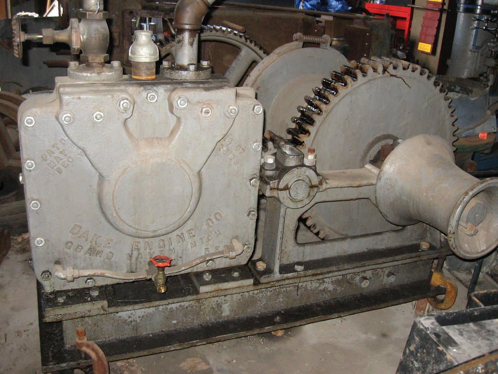
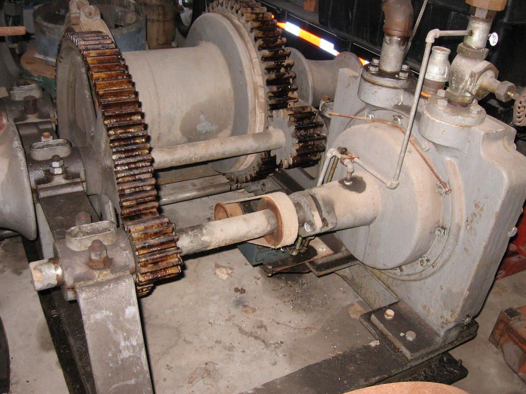
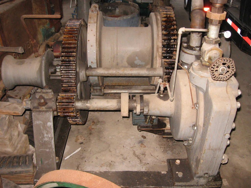
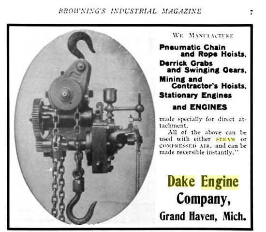
                                  Here are a few old cuts regarding the Dake engine, and a few photos of a Dake engine used in a winch application (winch photos used with permission of the owner).

                                  I have seen a Dake used as a boat winch, to pull up the anchor, and this is an ideal application since the entire engine is closed off from the sea water.

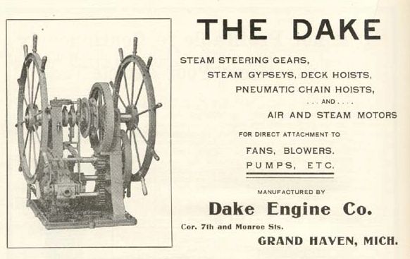
                                  And with its very fast reversing, and compact size, the Dake was also used as a steering engine on ships.

                                  I have also seen Dakes used on ships, to power ventilation fans and perhaps pumps and such, with the motive power being compressed air.

                                  I think the mine applications with the remote topside reverse valve were probably also compressed air operation.  This engine can operate in any position, assuming the oiler(s) are configured correctly.


                                  dake-forum-01.jpg

                                  dake-forum-02.jpg

                                  dake-forum-03.jpg

                                  dake-forum-04.jpg

                                  dake-hoist-01.jpg

                                  dakesquare.jpg

                                  dake-steering-application.jpg

                                  marineengr-dake.jpg

                                  Edited By PatJ on 07/07/2022 12:44:20

                                  #606968
                                  PatJ
                                  Participant
                                    @patj87806

                                    Much as I love the banter of the tea room topics, I can only use those to avoid shop work for so long.

                                    It is rather hot this time of year, with temps hovering around 100F every day, and about 70% humidity, so really no excuse is too flimsy to avoid shop work.

                                    The only way to finish an engine is to start on an engine, and so I have started working on the base pattern for the Dake.

                                    When I created the drawings for my Dake, I was not into backyard casting, and so everything was set up for a barstock build.

                                    This is coming back to haunt me a bit, and so I am having to fill the base pattern with wall patch compound.

                                    I could go back and reprint the base pattern, but I think at this point I will forge ahead, and just salvage the 3D prints that I have.

                                    As I got into foundry work and pattern making, I realized the importance of things like draft angle, fillets, overhangs, machining allowances, etc.

                                    What I do now is complete my 3D engine models without many fillets (perhaps no fillets), and with no machining allowances.

                                    Then I create the 2D drawings, which reflect as-machined dimensions.

                                    Then it is back to the 3D model to add fillets (using too many fillets initially really clutters up the 2D drawings), and add machining allowances. The fillets and machining allowances can be toggled on and off in the 3D program.

                                    And finally, in the 3D slicer program, I add a shrinkage multiplier of about 1.015, just prior to 3D printing the patterns or pattern pieces.

                                    My Prusa is too small to print the entire base pattern, so I printed it in four pieces.

                                    I had some slight bed lifting issues with one piece, and so I epoxied my base pieces together with them all being on a flat surface, and I will work out the warpage issues with filler.

                                    Since this pattern will be fragile, I think I will cast a permanent pattern in 356 aluminum.

                                    The filler is a mix-on-demand powder, used for patching wallboard.

                                    If I had set up my 3D model correctly, and if the 3D printed patterns all been perfect, then I would need very little filler.

                                    Alas this is not a perfect world, and so I am using a rather gloppy approach with the filler.

                                    Most of the filler will get sanded off, and luckily this filler sands relatively easily.

                                    The Durham's wood putty does as advertised, ie: it dries "hard as a rock", and so I don't use Durhams, since trying to sand it ruins the nearby wood or plastic pattern.

                                    rimg_9535.jpg

                                    rimg_9537.jpg


                                    rimg_9539.jpg

                                    rimg_9540.jpg


                                    rimg_9541.jpg

                                    rimg_9542.jpg

                                    rimg_9543.jpg

                                    Edited By PatJ on 23/07/2022 03:46:33

                                    Edited By PatJ on 23/07/2022 03:51:23

                                    #606969
                                    PatJ
                                    Participant
                                      @patj87806

                                      I have the base about 3/4 sanded out.

                                      I need to go take a few more photos of it.

                                      I use a sanding screen, which is used to smooth sheetrock joins.

                                      The open mesh on the sanding screen prevents clogging, and makes the sanding work go quickly.

                                      I could use a power sander, but for a piece this small, hand sanding is the only way to maintain good control.

                                      I have used the filler to create the fillets that I should have had in the 3D model, and to add a little draft angle here and there.

                                      .

                                      .

                                      Edited By PatJ on 23/07/2022 03:49:53

                                    Viewing 17 posts - 1 through 17 (of 17 total)
                                    • Please log in to reply to this topic. Registering is free and easy using the links on the menu at the top of this page.

                                    Advert

                                    Latest Replies

                                    Viewing 25 topics - 1 through 25 (of 25 total)
                                    Viewing 25 topics - 1 through 25 (of 25 total)

                                    View full reply list.

                                    Advert

                                    Newsletter Sign-up