Jowitt MkII Popett Valve Engine Build
Jowitt MkII Popett Valve Engine Build
Home › Forums › Work In Progress and completed items › Jowitt MkII Popett Valve Engine Build
- This topic has 47 replies, 14 voices, and was last updated 31 March 2020 at 09:24 by
 JasonB.
-
AuthorPosts
-
7 February 2016 at 20:07 #224316
 JasonBModerator@jasonb
INTRO
I first became aware of this engine when it apperared on the front cover of Model Engineer Magazine back in 1987 when Stan Bray did a two part construction article.

Stan's article was quite short and just gave general discriptions with a few photos but no drawings, this was his version of the engine.

Castings were available at the time but I never got round to buying a set, I think I was part way through my Minnie traction engine then.

The Jowitt has cropped up on a couple of forums over the years and I have posted the above photos to help people with more info and also mentioned that I would not mind having a go at one as I felt it was something that I could now fabricate due to a few years more experience than I had back then. I was at a meeting of my local traction engine modelers group towards the end of last year and a new member had seen my comments and kindly furbished me with an almost complet set of drawings. So no excuse! A former forum member also kindly shared a photo of a larger older model of the same subject which I have taken some details from
As is my usual way I decided to make the model a bit bigger but did show some restraint and settled on an enlargement ratio of 1mm to 1/32" or approx a 30% increase. It would be quite easy for anyone to reverse engineer my version back down to the smaller size if you have limited machine capacity or prefer imperial measurements. This is a proper metric conversion with whole numbers not silly decimals that you get by directly converting imperial to metric.
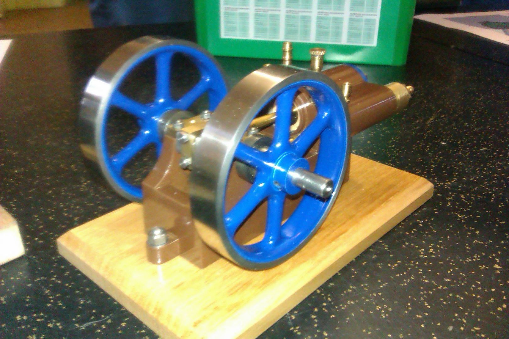
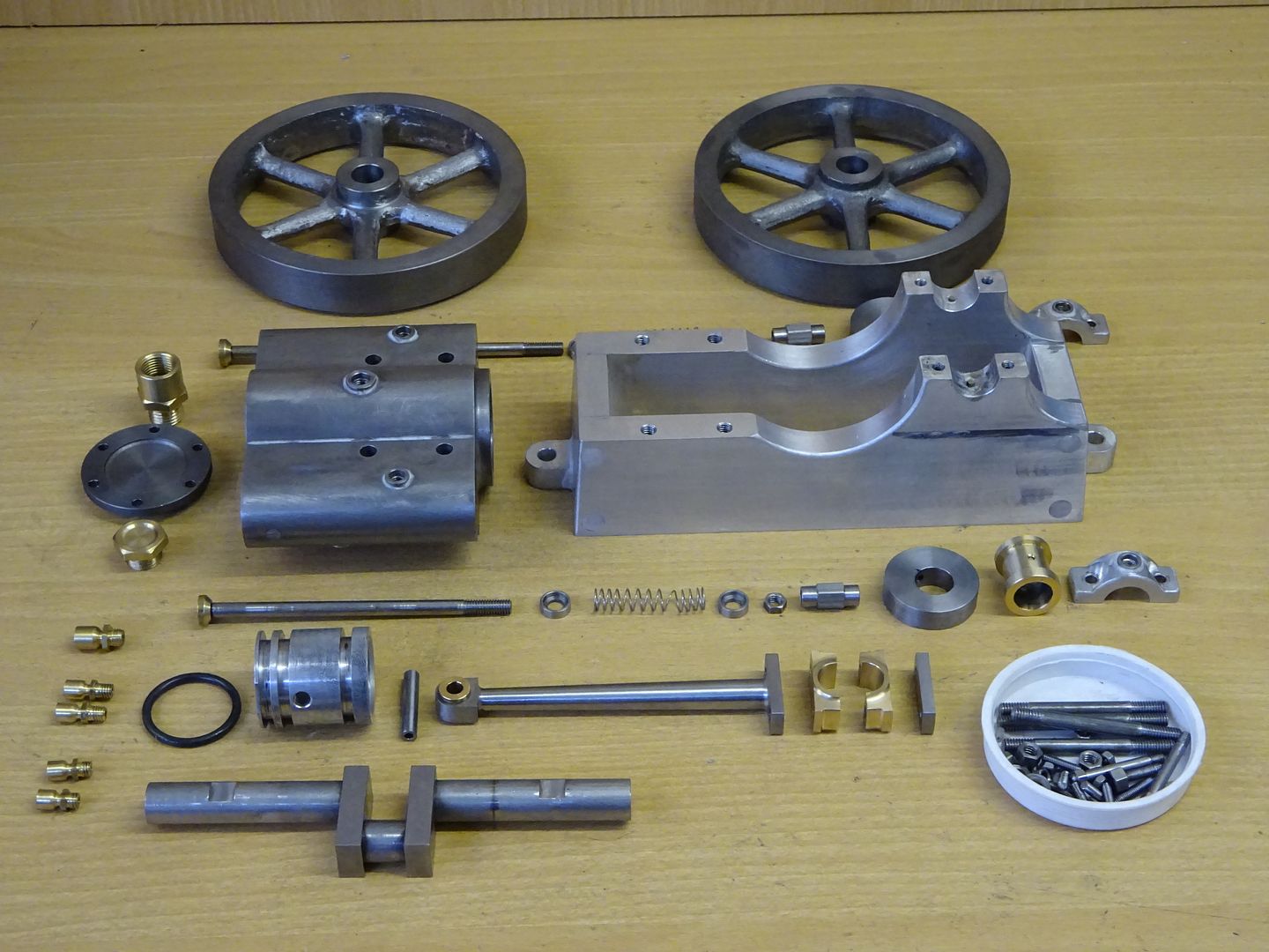
I prepared some drawing using Alibre and started cutting metal on 2nd January, by 31st I had a running engine and a week later it was painted and finished. I have called mine the "Jowitt MkII" and this is the 3D rendering to wet your appitite, next post I will start making swarf and drawings will be included.

Some of the parts could be simplified if you want to have a go but don't feel confident of things like shaping the cylinder or the angled cuts to the base and I will point these out as I go along. There are also other ways that most parts could be made, I have used whatI have but feel free to ask if you don't have some of the equipment that I show.
This is an interactive PDF so you can play about with teh sketch, may not work on a mac and you may need to trust the document.
J
Edited By JasonB on 07/02/2016 20:21:42
7 February 2016 at 20:07 #31116 JasonBModerator@jasonb7 February 2016 at 20:12 #224318
ianj
Participant@iansJason.
Looking forward to your next post.
This looks like a good build project for me ?
Ian
7 February 2016 at 20:15 #224319duncan webster 1
Participant@duncanwebster1Looks good to me, will the 3D model work in Inventor? #2 son has access to this at work.
7 February 2016 at 20:22 #224321 JasonBModerator@jasonb
Duncan I have added a link that should work on a PC, drawings will be in pdf format.
7 February 2016 at 22:13 #224339steve de24
Participant@stevede2433577Jason, I'm looking forward to reading this build thread. Thanks for posting. Steve
11 February 2016 at 20:25 #224969 JasonBModerator@jasonb
I have just received some additional information that Chelston Models also produced a larger version of this engine called the Jowitt Major but no other details about size etc.
The Model
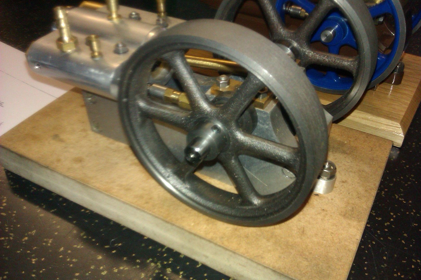
Chelston offered this with the base, cylinder and flywheels in cast iron the later of which were identical to Stuart 10 V/H flywheels and the extruded bearing material looks to have come from the same source. This engine is from the castings and made by Norman Peach who helped me with the drawings.

He also had a scratch built one with Aluminium base & cylinder and had used Stuart Flywheels & bearing material

I decided to use a block of cast iron for the cylinder as I had some to hand though Aluminium should be upto the job if you like to keep your hands clean. The two flywheels came from Reeves and are their "Perseus" ones which clean up easily to the required 97mm of my larger version.
Frame Sides
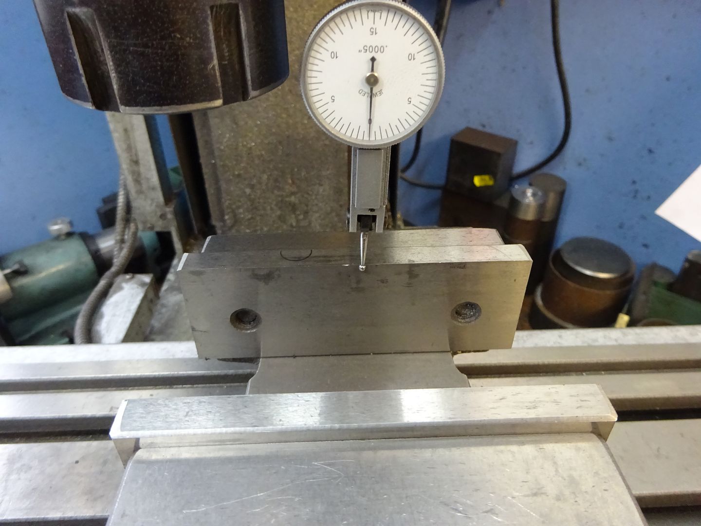
As a lot of the set up will use fixed jaw of the vice as a reference its as well to check it is true to the Y-axis before starting.

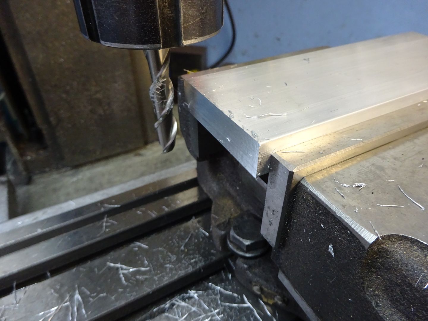
The first job is to saw off two pieces of 2" x 0.5" aluminium a little over the required 140mm, set it in the vice on parallels and square up one end of each.

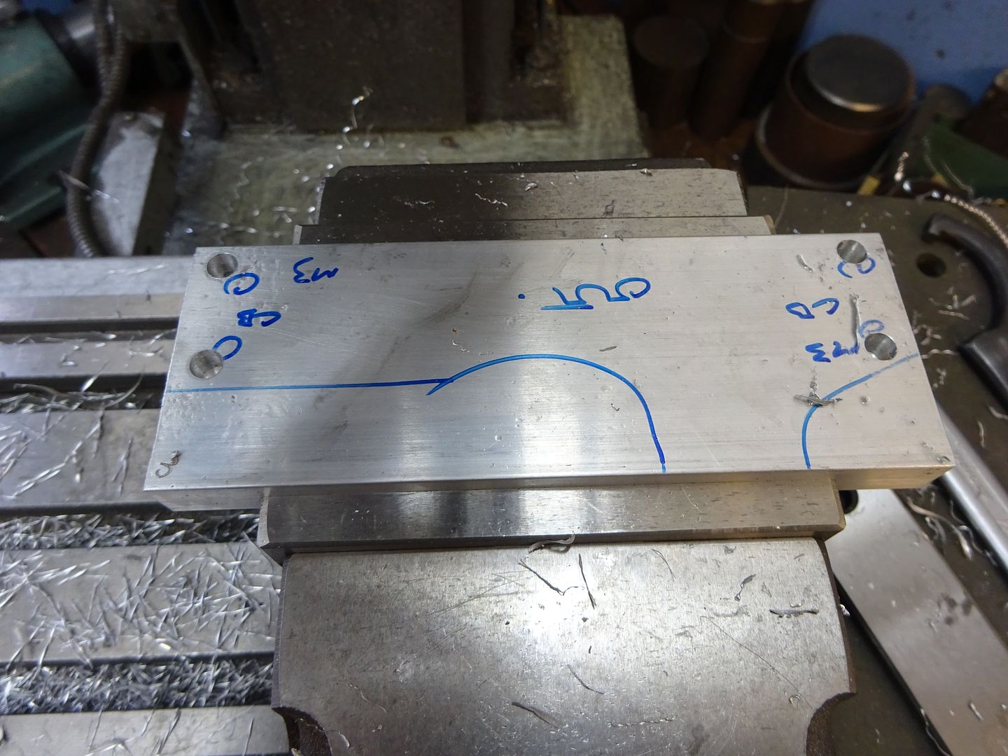
As the two sides are mirror images of each other it is easier to do most of the machining with the two pieces screwed together. After roughly sketching out where the holes & cuts go with a marker I set one side in the vice and used an edge finder to locate the bottom and previously squared end. The four M3 clearance holes can then be drilled and counterbored in one side, I set the holes 0.5mm higher than drawing to allow a skim to be taken off the bottom of teh extruded bar. If you don't have a counterbore then a 6mm milling cutter can be plunged in or an old drill reground to give an almost flat bottomed hole.
For the other side just drill two opposite holes clearance but tap the other two M3 which will allow the parts to be screwed together without the need for nuts sticking out the sides. You can see I have writen M3 against the ones to tap.

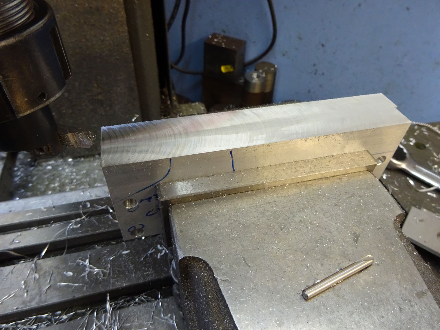
With the two plates stood back to back on a flat surface a couple of M3x12 cap head screws can be used to hold them together, then hold them in the vice bottom facing upwards and skim 0.5mm off to level the two surfaces and bring the screw holes to the drawing dimension of 5mm from the bottom. With that done grip them up the right way and mill the top down until you reach the required 50mm overall height. I used a flycutter for this but a couple of passes with a milling cutter will do.

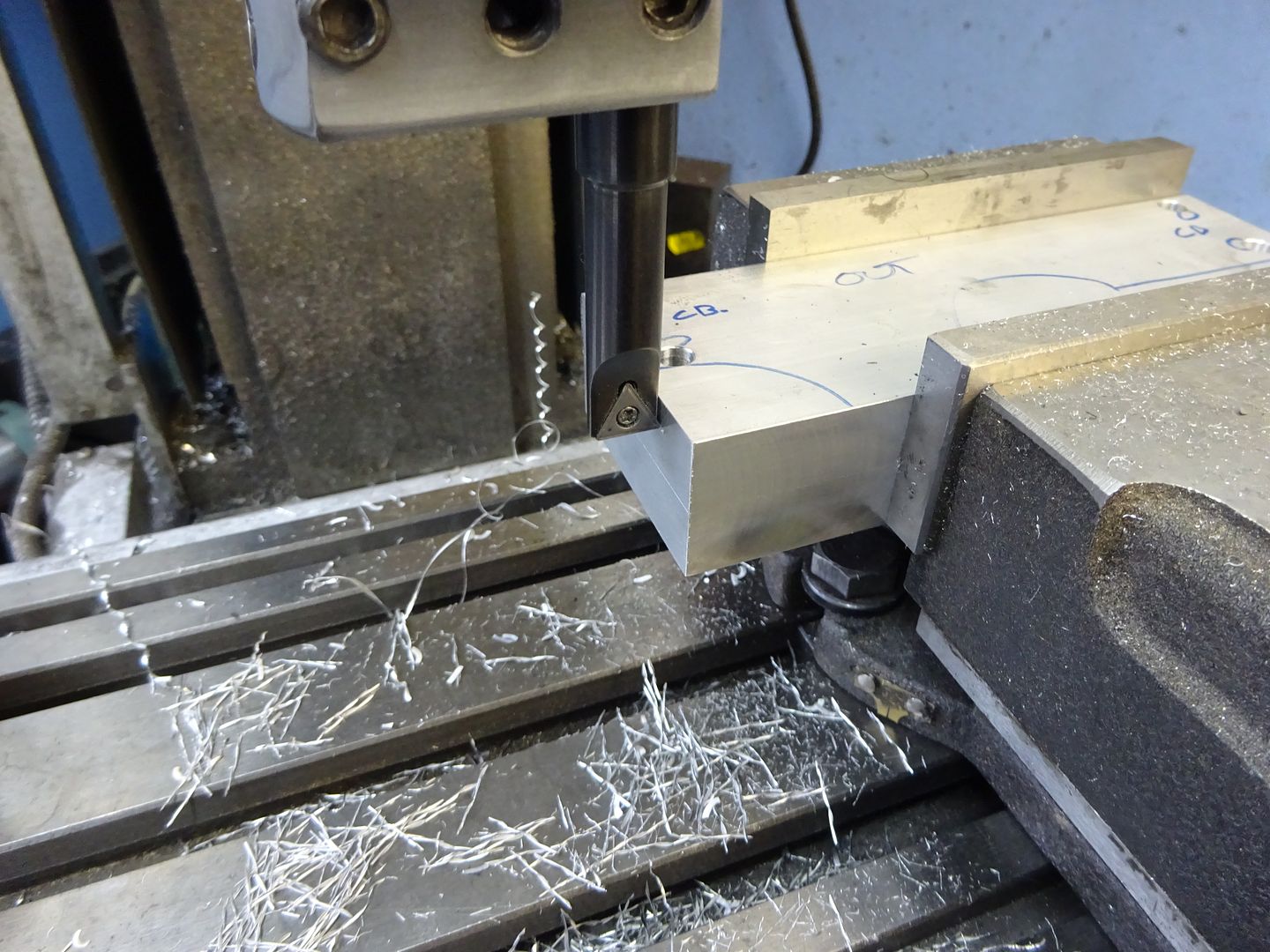
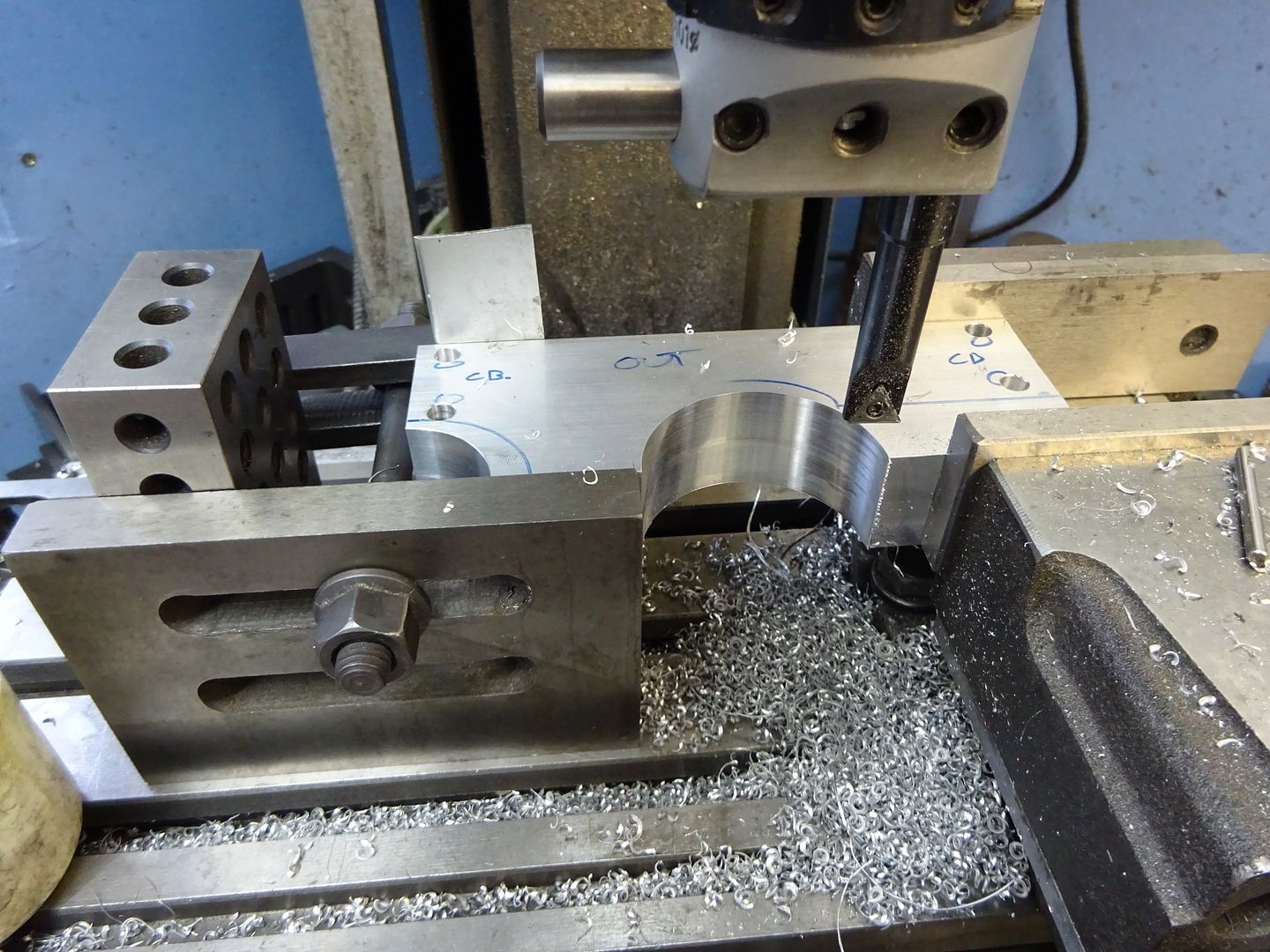
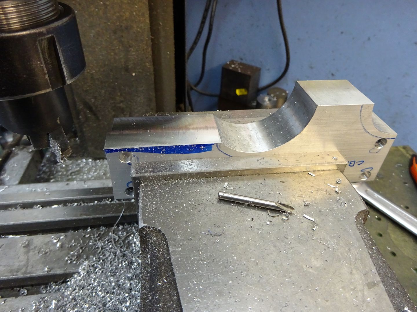
The curves that form the raised area for the crankshaft bearing can be formed with a boring head. Move the mill table so the spindle is 18mm away from the end of the work and then adjust the position of the cutter until it just kisses the end as you rock it back and forth by hand, this is an easy way to set the required 18mm radius.

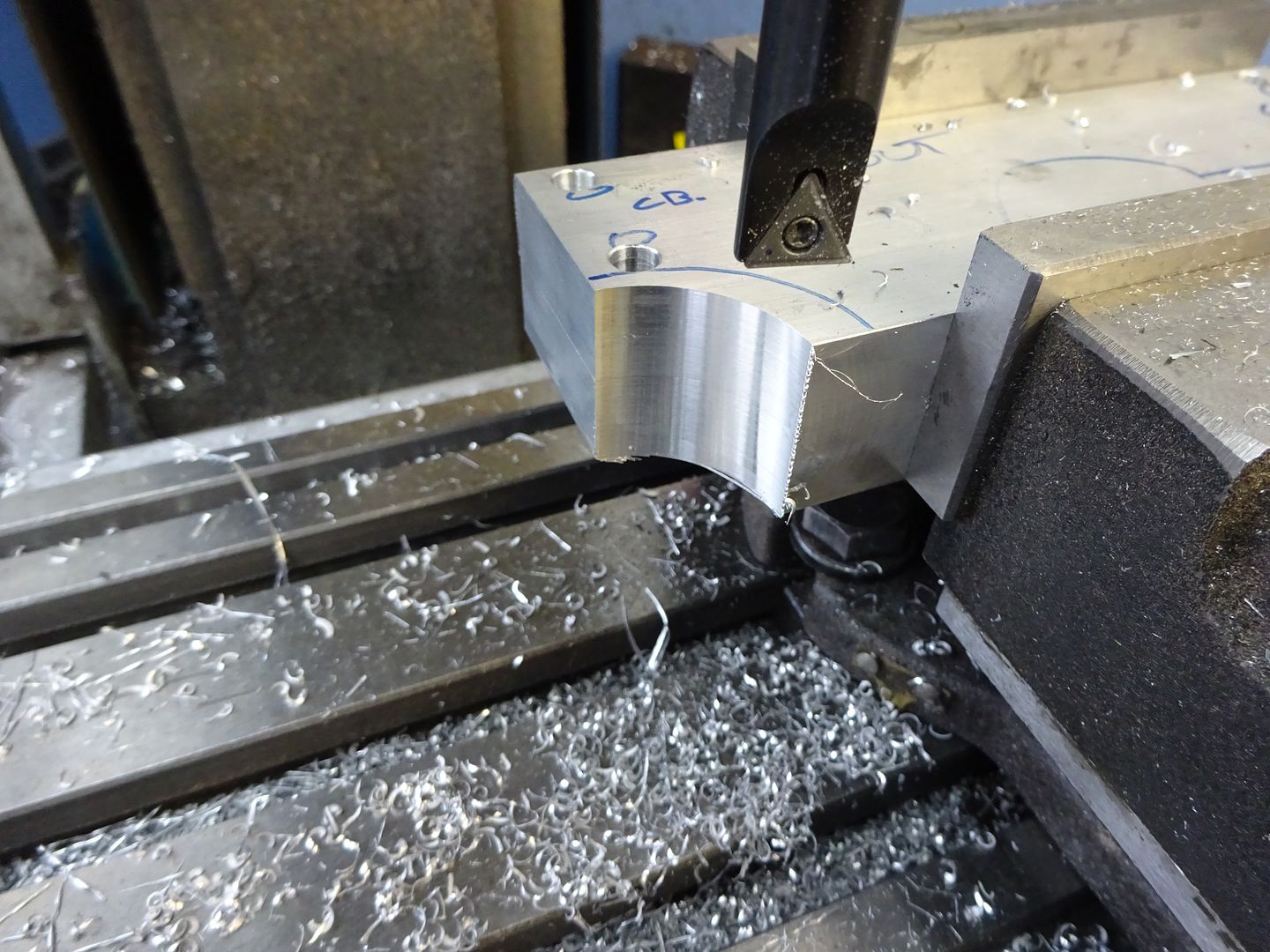
With the spindle 50mm from the vice jaw datum (bottom of frame) make a series of plunge cuts in 1mm steps until the spindle is 2mm in from the end of the work.

A similar method is used to set the radius on the other side to 24.5mm and the larger radius cut in the same manner.

These two curves could be sawn & filed if you don't have a boring head.
to be continued
Edited By JasonB on 11/02/2016 20:27:23
11 February 2016 at 20:31 #224972 JasonBModerator@jasonb
Frame sides continued
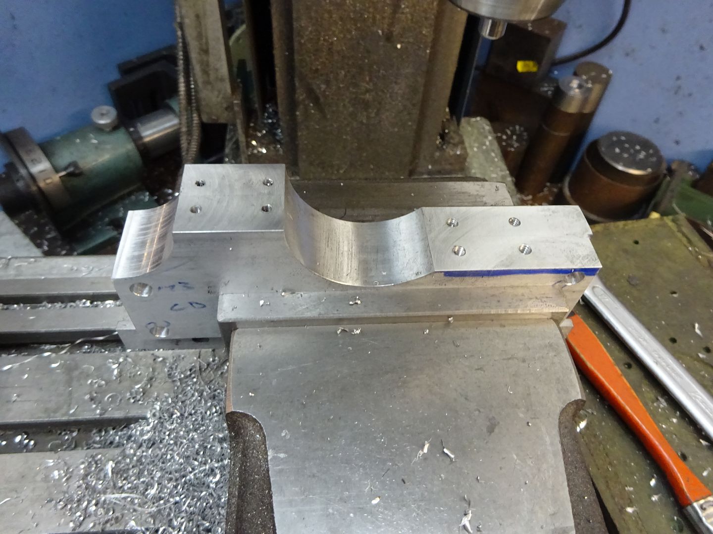
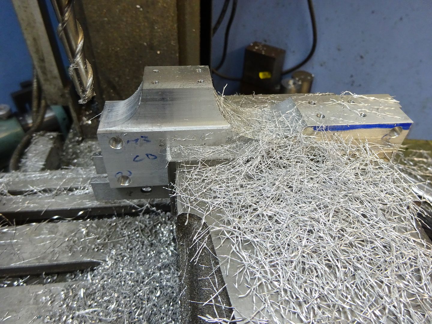
Scribe a guide line where the cylinder will sit 32mm up from the base and saw off the waste material leaving a mm or so to cean up on the mill. Save the two pieces that are cut off as they will do for the bearing caps later. Set up in the mill and machine until the required 32mm finished height is reached.

Locate the end of the frames and find the centre line of the pair using an edge finder and then drill and tap for the bearing caps and cylinder mounting studs. Note that the bearings are 5mm from the inside edge of the frames (ctr of pair) and the cylinder studs 6mm.

At the same setting the two vertical edges around the bearings can be reduced to the finished 10mm width, I used a 10mm dia cutter so it was simple to set the spindle 15mm from centre for the final cut. I took full 18mm depth cuts 0.5mm per pass using one of ARC's HSS cutters for Aluminium which romped through the metal.

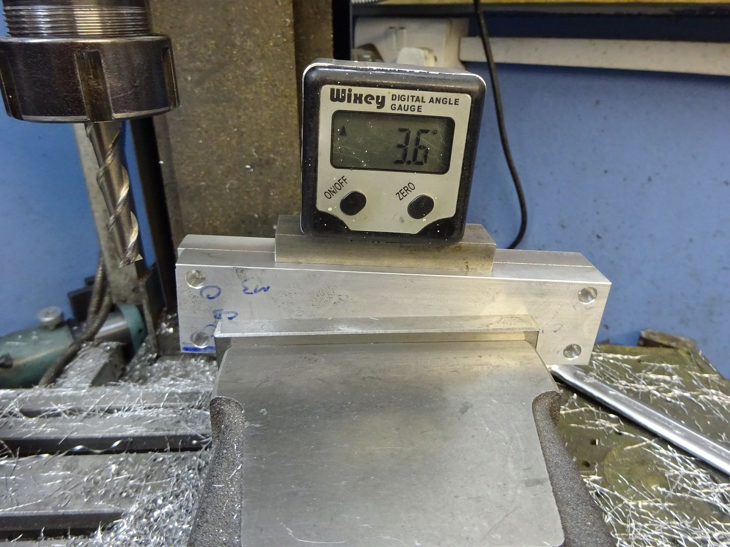
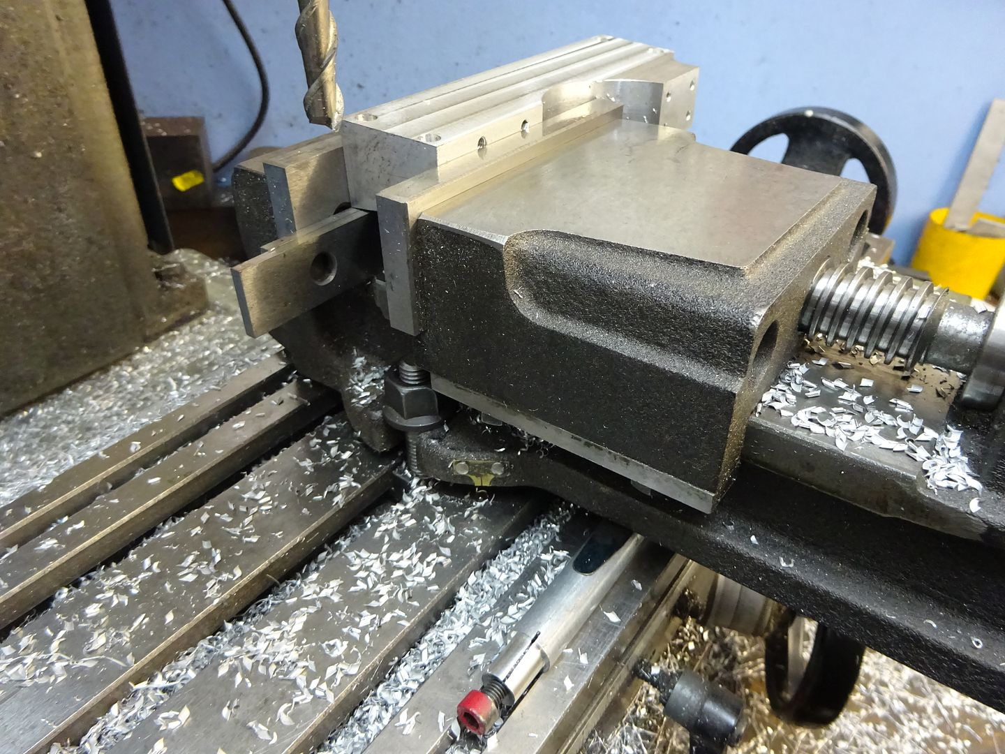
With the side frames upside down and held at 3.6deg the sloping ends can be cut and the overall length brought down to 140mm at the base.

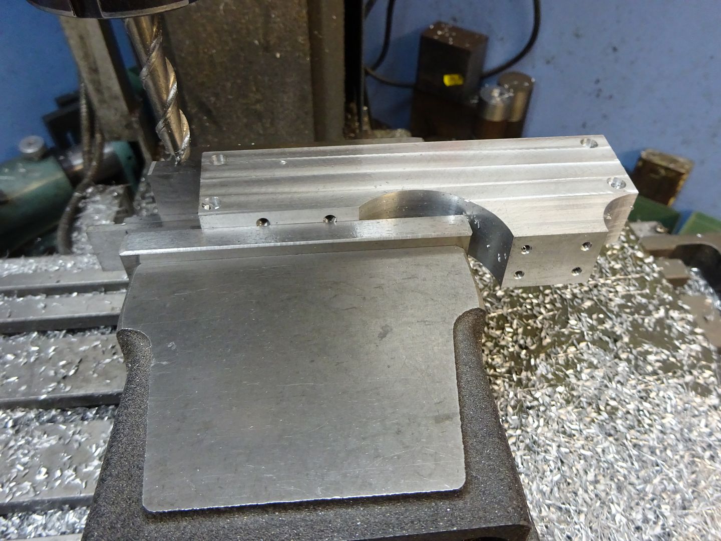
I don't have a tilting vice but its easy enough to pack up one end of a standard vice and then lightly bolt back down to the table to avoid distortion. The slope on the sides can then be milled to the same 3.6deg angle aiming to get a smooth transition where it meets the vertical face .


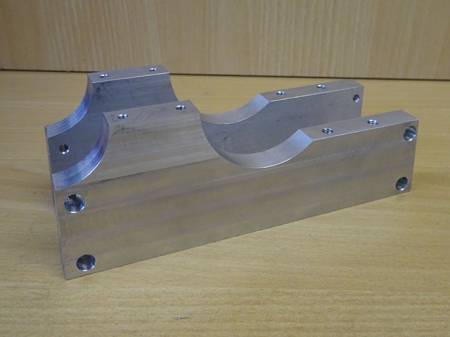
That is the side frames done, the pin hole to stop the bearings rotating will be drilled later

If you feel the sloping side may be a bit beyond what you are capable of then 10mm material could be used and the base done with straight edges. Next time I will cover the frame ends and feet.
J
Drawing to download If anyone finds errors on teh drawings please let me know so they can be corrected
18 February 2016 at 17:42 #225957 JasonBModerator@jasonb
Frame Ends
Start by machining two pieces of aluminium to 32 x 26 x 12mm

Locate the far edge and right hand end then move in 5mm and drill and tap M3, move along 22mm and do the other hole. If you use a vice stop then the other three pairs of holes can be done without having to locate the edges each time

With the vice fixed jaw and stop still clocked in the bottom slot is easily located and using a 12mm dia cutter taken to 8mm deep followed by drilling & tapping for the M5 thread.

Next set the ends to 3.6degrees and flycut or mill the slop on the outside face to complete

Feet
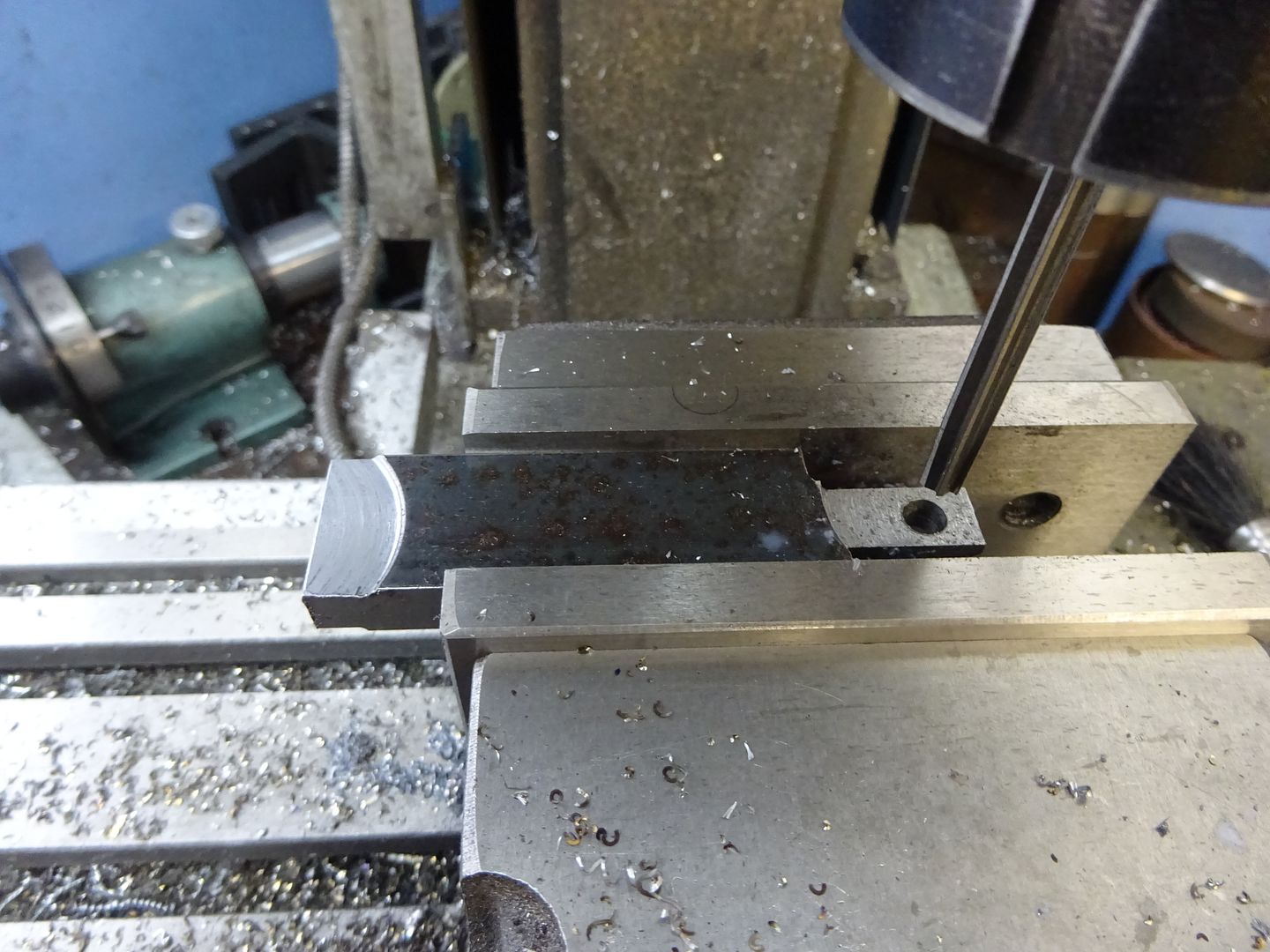
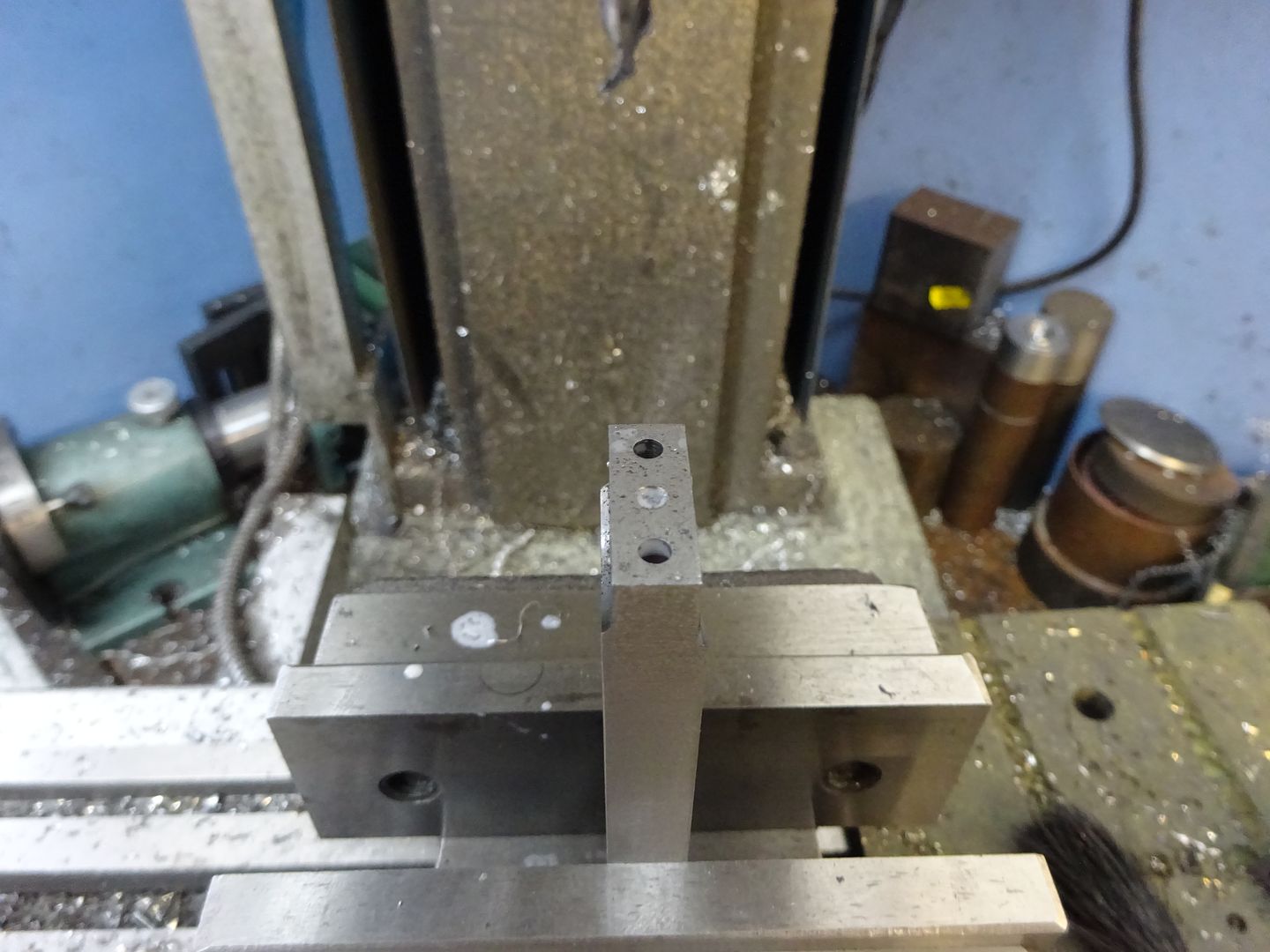
Machine two bits of Aluminium to 12 x 8mm and at least 24mm long, locate an edge and end then drill the two 5mm holes countersinking one to take the head of an M5 CSK socket screw.

Pop a 5mm pin into the hole and set a milling cutter 8.5mm above the vive jaws and then take a series of tangental cuts which will leave a facetted face as seen on the one in the vice. This can quickly be cleaned up with a file to leave a nice smooth curve as in the foreground.

A few M3 and M5 screws can be used to see how it all goes together, don't drill out the M3 threads in the side plate to clearance yet.
J
23 February 2016 at 20:35 #226611 JasonBModerator@jasonb
Bearing Caps
Start by machining two pieces of aluminuim to 10 x 10 x 28 and then hold in the vice and locate a side and end. Drill the two 3mm holes then the 1.5mm oil hole right through followed by a 6mm 2 or 3 flute cutter plunge 3mm deep to cut the socket for the bush.

Changing to an 8mm cutter plunge 6mm deep to form the counterbore to the 3mm hole and then the flat area 4.8mm in from the end.

The two side frames can now be screwed back together and the caps screwed into place. Locate the centre of the crankshaft hole, spot drill then open up with 6mm and 10mm drills and finally use a 12mm milling cutter to take the hole to size.

With the frames stood upright the 1.5mm holes for the bearing retaining pins can be drilled using the matching hole in the cap as a guide. Mark the caps before removing so you can assemble them in the right position in the future.

Using the same method as for the feet the tops of the caps can be rounded over to 10mm radius

Oiler Bush
These are simple turning jobs from 6mm rod. Face the end, drill 3.5mm and tap M4 x 0.5 metric fine then part off two 5mm lengths. If you don't have metric fine then 5/32 x 40 ME or M4 x 0.7 will do. These bushes can be fixed into the bearing caps with Loctite or JBWeld
Main Bearings
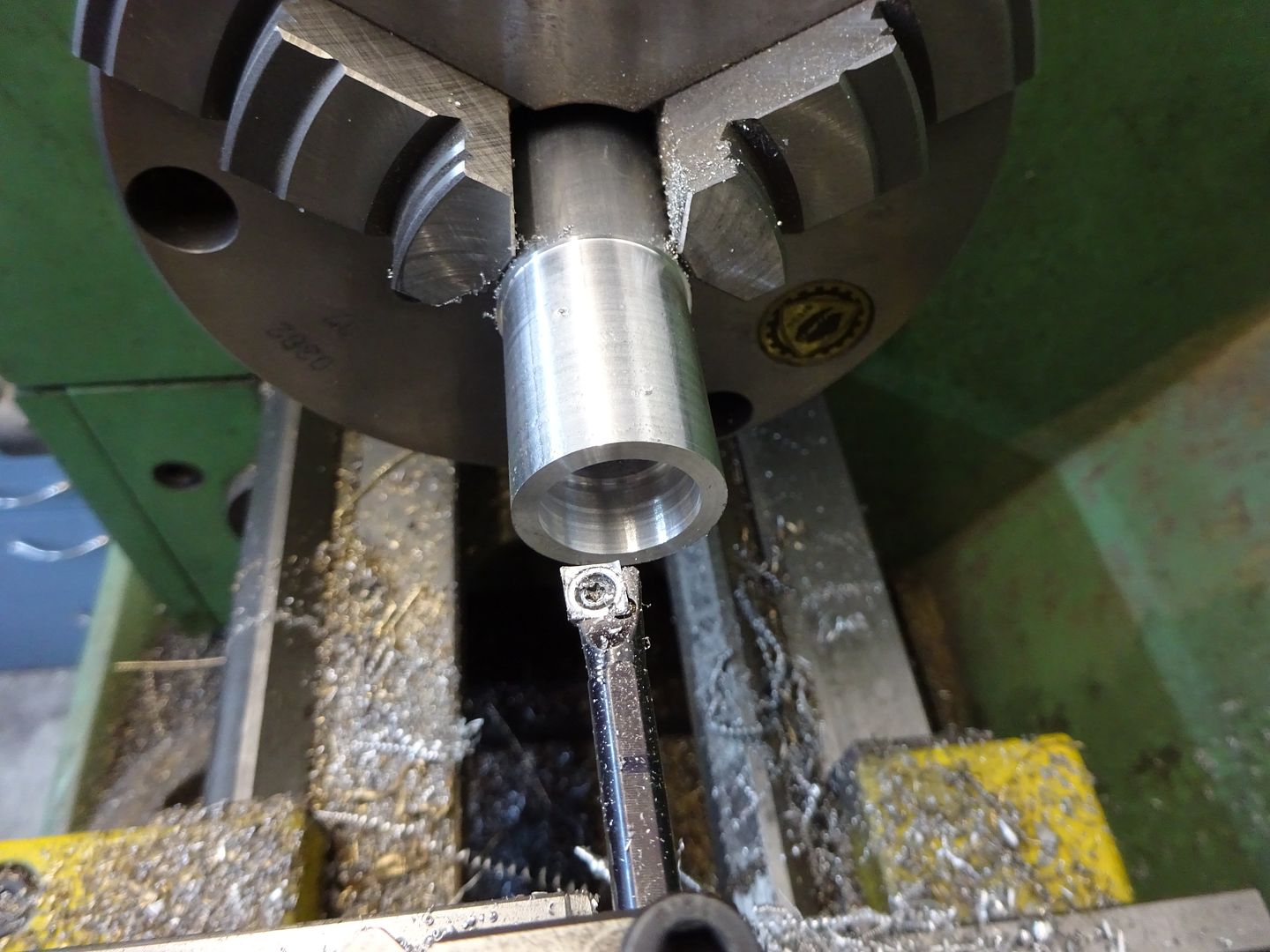
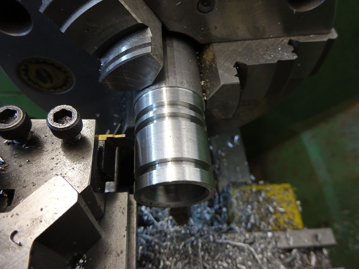
Turn down enough material for two bearings and parting off allowance to 15mm. Face off and drill in stages to 9mm, bore out to 9.8mm and then ream to 10mm.

Use a parting tool to cut the 12mm dia waist groove 10mm wide and then part off, repeat for the second bearing.

And a quick try out to see how these parts go together.

Edited By JasonB on 02/03/2020 18:21:44
1 March 2016 at 19:35 #227810 JasonBModerator@jasonb
Cylinder
Probably the most involved part on the engine, if you don't feel upto it then the curved top and sides could be left square so you have a + shaped cylinder or even just leave it as a rectangular block.
I used and have shown Metric Fine threads on the drawings but ME 40tpi or even standard Metric Coarse could be used if you don't have the fine series taps & dies
The cylinder can just be got out of a piece of 40×80 cast iron bar as it comes out a little over these nominal sizes. I started by sawing off a lump with enough allowance to clean up to the required 64mm length.

Next the top and bottom surfaces were cleaned up on the lathe taking similar amounts off each to reach the 36mm finished thickness.

Then over to the mill to take a light cut off one edge

Then rotate the work 90 degrees in the vice and using a square make sure the first edge is true, a light behind helps to see any gaps. Once set the second edge can have a light skim. followed by the other two to bring the block down to size.

Mark the position of the bore in the middle of one end and punch.


Back to the lathe and set the punch mark to run true in the 4-jaw using a sprung centre and dti

Using a standard right hand tool the spigot was roughed out

Then completed with a round nose tool to give the 1.5mm internal radius, the punch hole saw also enlarged with a spotting drill.

And then starting with a 6mm bit progressively opened up to 22mm with a range of drill bits.

This allowed room for a sturdy boring bar to fit and take the bore out to the 24mm diameter finished size.

Then lightly chamfer the corner so the O rings don't get damaged when fitting the piston.

To be continued
1 March 2016 at 20:14 #227816 JasonBModerator@jasonb
Cylinder continued
With the main bore in place next we can start to put some shape into the block. Starting with a newly purchased roughing mill from ARC the majority of the waste was removed 7.5mm tall and 3mm per pass.

And then with a 3-flute cutter finished to the required 8mm depth and 46mm width

Without disturbing the work the four M4 clearance holes for the hold down studs were added

Now working from the top the two waste areas can be milled away as before and the holes for the oilers added. I counterbored the cylinder hold down holes but unless you are using large washers that is not actually needed.

The three tapped holes can then be counterbored 1mm deep for bosses like the bearing caps.

Next the back end of the cylinder can have the six cover holes drilled & tapped M2.5, note I have altered their position on the drawing which avoids a clash with the steam passages.

The inlet side is drilled 9mm x 16mm deep and tapped M10x1 followed by drilling and reaming 4mm the rest of the way through, a standard 4mm drill should just reach.

The exhaust side is again tapped M10x1 by 16mm deep then drilled 6mm for a further 16mm before reducing down to a reamed 4mm hole the rest of the way through, finally use a 8mm CSk bit to form the valve seating at the bottom of the M10 hole.

The two steam passages can be drilled 3.3mm into the cylinder bore and the outer part tapped M4 for plugs.

The last hole is the M6x0.75 exhaust port which is drille dup until it breaks into the 6mm hole and then counterbored 8mm x 1mm deep

You could stop at this stage

To be continued
1 March 2016 at 20:28 #227820 JasonBModerator@jasonb
Cylinder continued
To round over the top of the cylinder I turned up a temporary plug so one end could be supported by the Rotary table tailstock and gripped the other end with the jaws expanded inside the bore. It was then just a case of taking a cut rotating 4 degrees (one turn of the handle) and then taking another pass.


The sides were done in a similar way, the tailstock in the 4mm hole and to hold the other end I made up a locknut so the M10x1 tap could be used as an arbor.

A bit of work with a file will soon blemd in the facetted cuts into a nice curve.

Finally the dummy bosses can b estck in with a dab of loctite

J
Edited By JasonB on 03/03/2016 16:01:08
3 March 2016 at 15:28 #228083Emgee
Participant@emgeeHi Jason, can you check the Dropbox message.
Emgee
3 March 2016 at 16:04 #228085 JasonBModerator@jasonb
Message or link?
I have reposted the link just incase there is a problem, sometimes does not open well on IE but OK on Chrome
3 March 2016 at 16:18 #228086 JasonBModerator@jasonb
Ah got the message.
Download the file from dropbox and save it on your harddisk then open it from the hadrdisk not via the Dropbox site. You will also need to trust the document.
Also needs flash so may not work on ipad etc
This is about the 3D pdf of the assembled engine, if you want to be able to move around it and zoom in etc that is how to do it from Dropbox
Edited By JasonB on 03/03/2016 16:22:14
3 March 2016 at 17:53 #228108Emgee
Participant@emgeeOK Jason, did as suggested and "activate" was there so could move the model around.
Emgee
13 March 2016 at 20:18 #229799 JasonBModerator@jasonb
Cylinder End Cover
This is quite a simple piece after the cylinder, I used a stub end of cast iron bar but steel would do. Turn down to 30mm dia and then turn the 24mm dia x 3mm long spigot and part/saw off

Now holding by the spigot face off to 3mm thick and decorate as desired, I went for a simple 20mm dia recess with a rounded edge. The original CME engine carried the CME logo here.

Now over to the mill to drill the six M2.5 clearance holes on a 30mmPCD and thats the cover finished.

Eccentrics
I turned down a piece of 1" bar to 24mm long enough for two eccentrics, parting cuts and a little to clean up afterwards then set the bar in the mill vice, indicate the middle then move 1mm to the back and drill and ream out to 10mm dia. It could also be done in the 4-jaw but I could not be bothered to change it over.

You can then part off two slices and finish to 6mm thick, drill and tap for a M3 grub screw in each.
J
Edited By JasonB on 14/03/2016 20:26:34
14 March 2016 at 20:31 #229965 JasonBModerator@jasonb
Thanks to Marcus for pointing out I had put the main bearings onto two drawings, sheet No 6 has now been revised and the link at the end of the last post will take you to it.
Good to know someone is reading the thread
 17 March 2016 at 19:30 #230484
 JasonBModerator@jasonb
Crankshaft
I had intended to make this from 10mm PGMS (Precision Ground Mild Steel) which is what I have spec'd on the drawing but could not pick up any at the time I wanted it and postage on one bit of metal would have been high so I opted for some 10mm Stainless steel which I already had, either would do the job.
The main shaft can be turned down to 112mm long which is right for the two Perseus flywheels that I used. If you buy different flywheel castings or want to add a pully then you may need a longer length.
The pin can be faced off to give the required 22mm overall length then reduced at both ends to 8mm dia for a length of 6mm

Machine up two pieces of mild steel 12x6x24mm and then holding them in the vice drill and then ream the 10mm and 8mm holes. If you use a vice stop it saves having to locate the edge of the second web.

Clean up all the parts with solvent so the loctite will make a good bond and then start assembly. I did it in two stages, firstly stick the pin into the webs using the shaft to keep things lined up. Then when that has set the pin/webs can be bonded to the main shaft, I supported them in a couple of Vee blocks while things dried.

I'm more used to silver soldering crankshafts or cutting from solid so decided to pin the joints for good measure. Drill 1.5mm cross holes and lightly countersink.

Then push some 1.5mm steel rod through the holes and pein over the ends with a hammer.

All that remains is to cut out the middle of the shaft that is not needed and file the ends flush with the insides of the webs, the ends of the pins can also be filed down at the same time.
Check that the crankshaft turns smoothly in the bearings and make any adjustments that may be needed as its easier to do it at this stage. Once happy that everything turns freely the base can be joined together. I used a small amount of JBWeld spread over the 4 joints and then screwed the parts together on a flat surface making sure that the crankshaft turned as the screws were nipped up.

If you leave the feet off it is easy to clean up across the whole end to remove excess filler and any high spots if the parts don't quite all lay flush. Once that is done the feet can be stuck in the same way. I prefer to use an easier to sand filler for cosmetic filling so some U-Pol car body filler was used to fill the screw holes. The same filler can be used to add a fillet around the feet and oiler bosses.
J
18 March 2016 at 09:51 #230534Chris Evans 6
Participant@chrisevans6Jason, I am not a model maker as pre war motorcycles are my main interest but reading such a common sense clear build log as yours I am tempted to make one. What I like is the lack of chasing accuracy beyond what is required to make it work. When my work load gets down a bit I will make a start. Chris.
21 March 2016 at 18:17 #231087 JasonBModerator@jasonb
Good to see you are tempted Chris, its quite an enjoyable engine to build and does allow a bit of leway with how it is made. Indeed some people tend to spend their time looking for the elusive last 0.0001" but I prefer to get on and build something. Not to advocate sloppy work but a lot of the time super accuracy and fine limits are not needed.
Piston
At a shade under 24mm dia the piston will come nicely out of a piece of 25mm or 1" bar so pop a bit in the chuck with enough poking out for the part and turn down to the required 23.95mm which will leave a little room for the piston to expand due to the heat if you decide to run on steam.
At the same setting the end can be faced off then starting with a spotting drill most of the waste can be drilled out to say 12mm before changing to a boring bar to open up the hole to the required 16mm dia by 24mm depth.

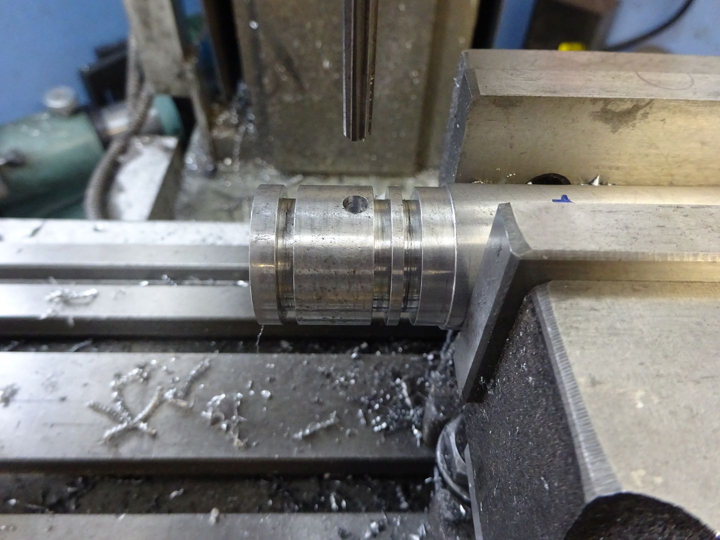
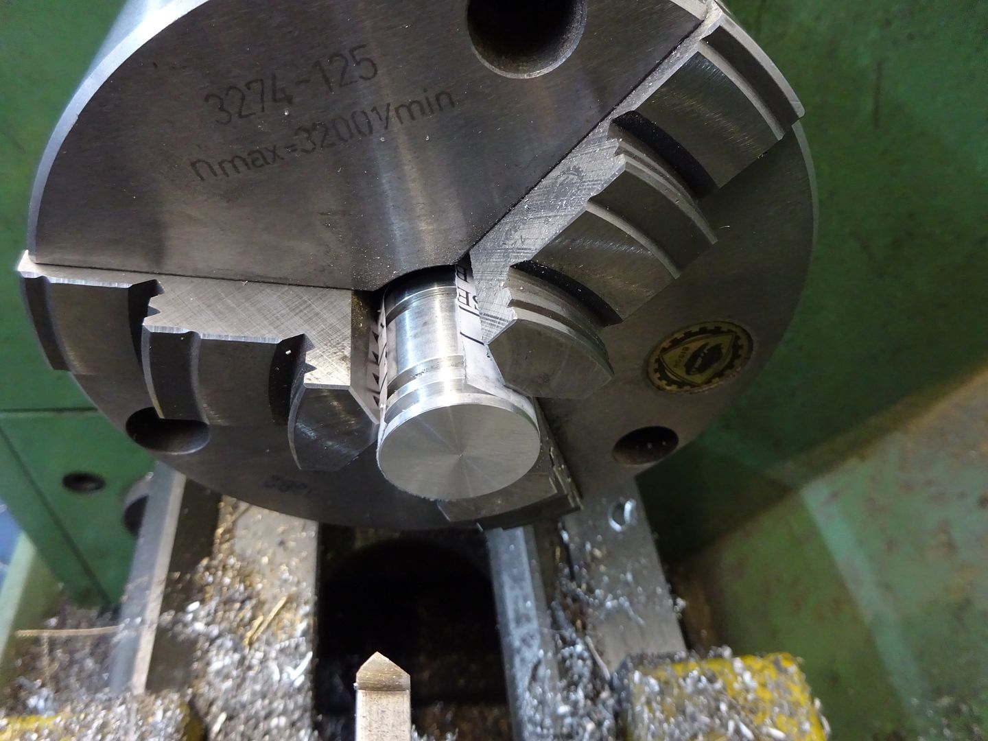
The piston ring grooves can also be added at this stage, I have given dimensions from the end of the piston to the left of the groove so simply touch the edge of the parting tool against the end of the piston and then wind the topslide along 8mm for the first groove and 26mm for the second. Bring the topslide back as you make a couple more parting cuts until the grooves are 2.6mm wide. Ease all the external corners so the O rings don't get nicked when fitting.
You will notice that I cut 3 grooves as per Stan Bray's sketch but two will be quite adequate and is what I have shown on the drawings. My engine runs fine on air with just one ring in the groove furthest from the crank.

Over to the mill now, locate the centre of the piston dia, the ruler trick will do and then drill and ream a 4mm hole 17mm from the open end. I don't have many machine reamers but find that a hand reamer held in a collet and run at slow speed works perfectly well and in these sort of sizes tend to drill 0.2mm under dia so in this case drill 3.8mm.

Saw or part off the piston a little over length then with something to protect the finished surface lightly hold in the chuck while the end is faced back to get the final 28mm length.

O-Rings
I used Vitron O-rings: 19.6mm ID x 2.4mm section, bought on e-bay # 371503929586
Wrist Pin
This is just a short length of 4mm silver steel (Drill Rod) faced to 21mm long and with a 2mm dia x 5mm deep hole in each end.
Wrist Pin Pads
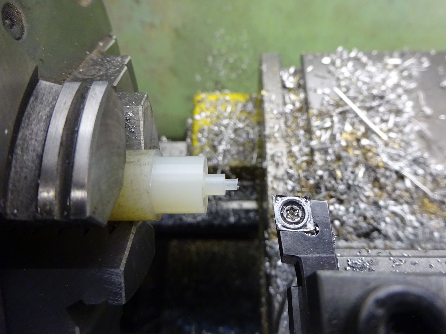
These can be from Acetal, nylon, or any other similar material or bronze if you prefer doing them in metal so long as it is softer than the iron so they protect the bore from the wrist pin. Turn a short length to 4mm and then the 2mm spigot and finally part off to give a 1mm thick head.

J
31 March 2016 at 19:15 #232717 JasonBModerator@jasonb
Conrod
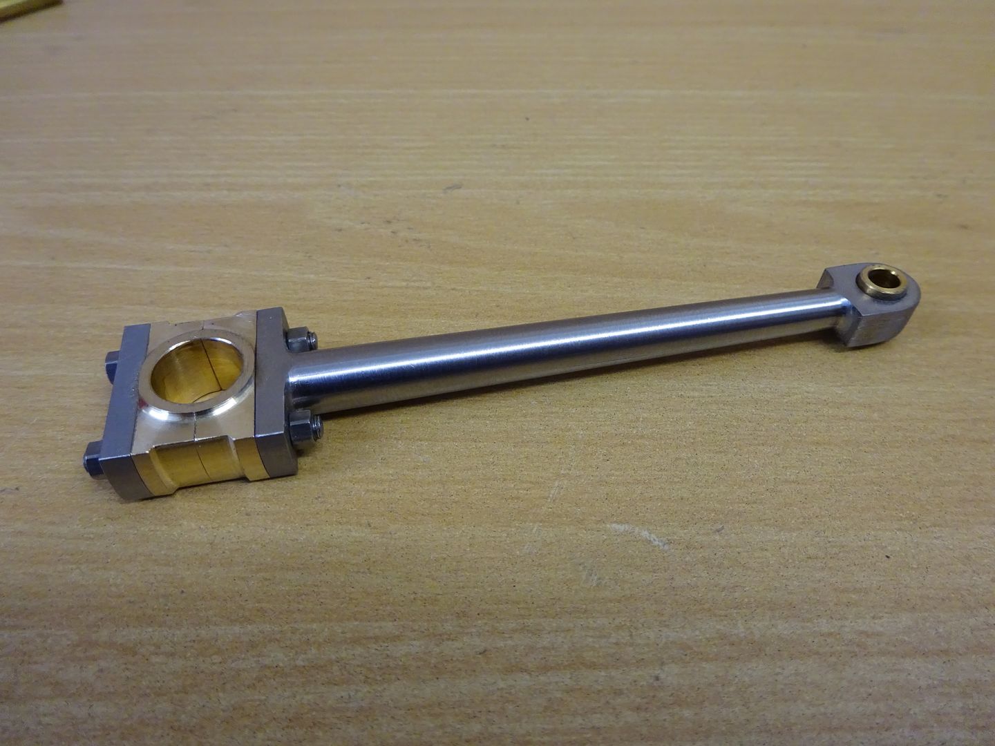
I used a piece of 12x25mm black mild steel bar for this a few mm longer than the finished size. Start by maching one end down to 10x22mm and then the other to 6x10mm, square off the 10×22 end and then drill and ream 6mm dia 80mm from that end.

Put a small BS0 centre drill hole in each end and also drill the two 3mm holes in the big end.

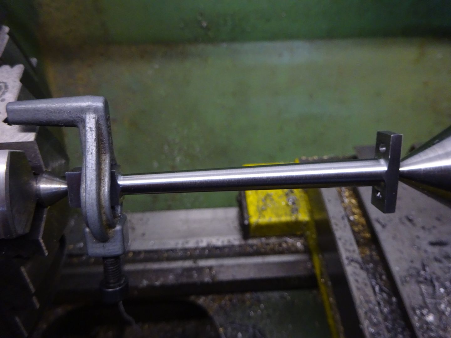
Use a hack saw to remove most of the waste then set up on the lathe between centres, firstly rough the rod down until its parallel and a little over 8mm then set the topslide over and finish to the final taper going from 8mm down to 6mm with a round nose tool.

Finally the small end can be rounded over which wil remove the ctr drill hole
Big End Bearings and Keep Plate
I will describe these together as some of the work can be done on both at the same time.
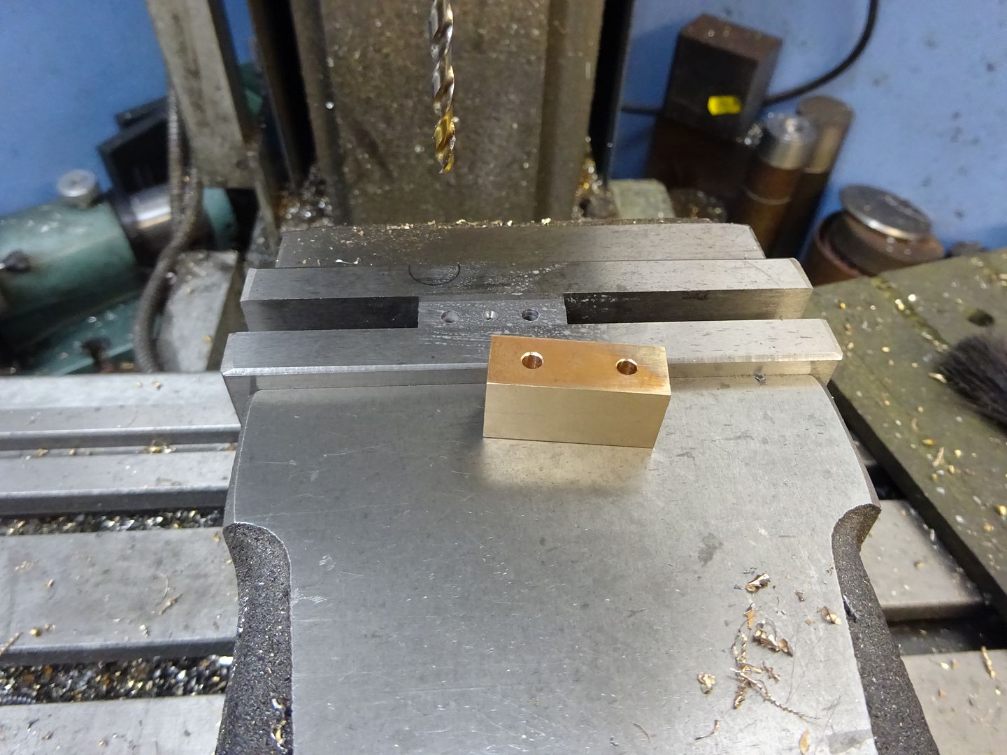
For the bearings machine two pieces of bronze to 6mm thick and then soft solder together, once cool machine the pair to the final 22mm x 12mm. I find it easier this way than trying to line up two pieces that are finished size when soldering.
The keep plate is just a piece of 3mm thick material machined to 10mm x 22mm.
Drill the 3mm holes and include another small ctr drill hole in the keep plate.

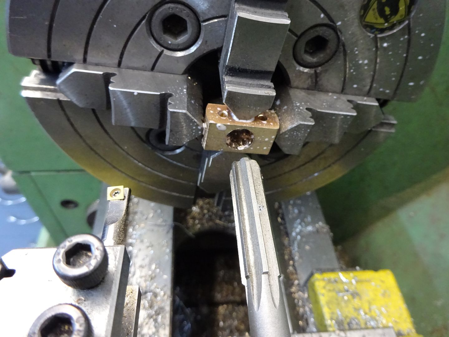
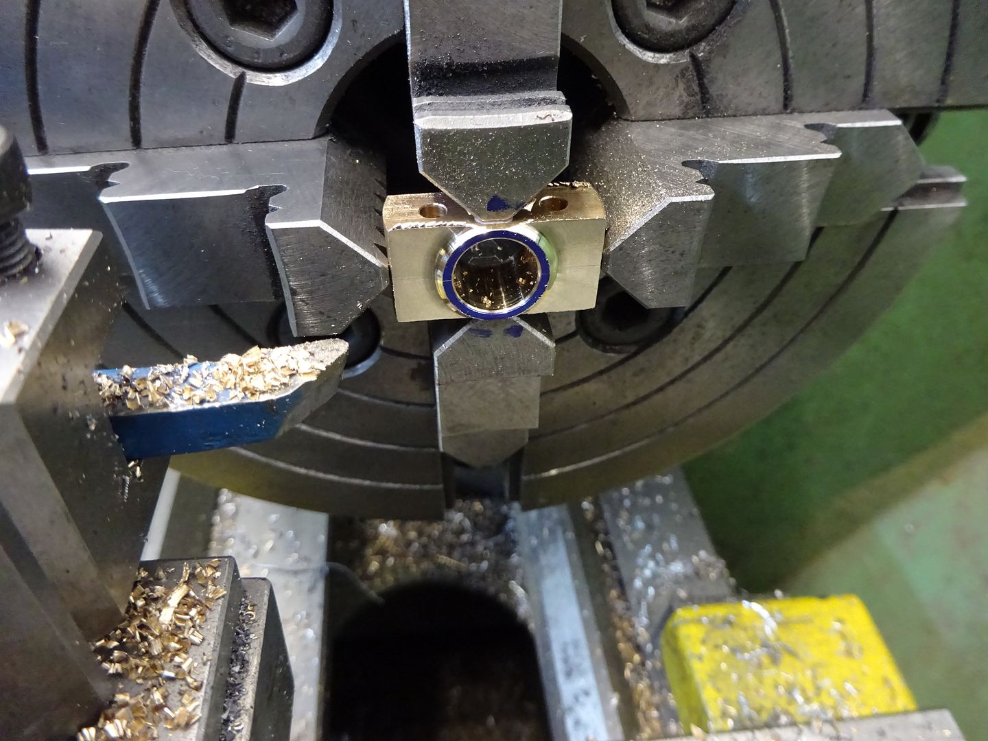
Lightly hold the two bearing halves in the 4-jaw and drill, bore then ream out to 10mm. Take it easy when drilling the hole as a blunt drill can expand pop the solder drill apart, you may notice from the splashes that I have also used some soluable oil which helps keep the heat down when drilling and reaming bronze, general turning can be done dry.

A small round nose tool can then be used to remove 1mm of material on each side blending nicely into the 12mm dia.

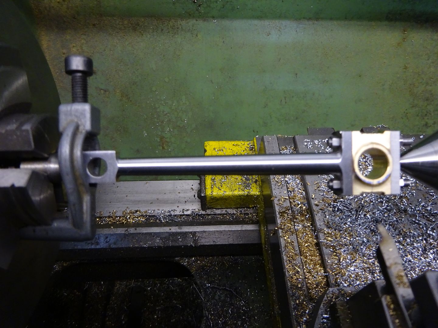
The parts so far can be assembled with a couple of temporary nuts and bolts, held between ctrs and then the big end turned down to 22mm dia and the round nosed tool used again to cut the 20mm dia waist in the bronze. Mark the parts so they can go back together the same way. Unsolder the bearings and give the mating faces a light rub on some wet & dry.

Small End Bearing
This is a straight forward turning job, the bearing can be pressed or loctited into the conrod.
Finally thread the ends of a couple of bits of 3mm rod and add a nut each end to hold things together. Test the fit on the crankshaft as the bearings may have closed up a bit when the solder was cleaned off, if so just run the reamer through again.

J
10 April 2016 at 19:49 #234056 JasonBModerator@jasonb
Valve Parts
Most of these are simple turning jobs so I have not taken many photos but here goes.
Inlet & Exhaust Rods
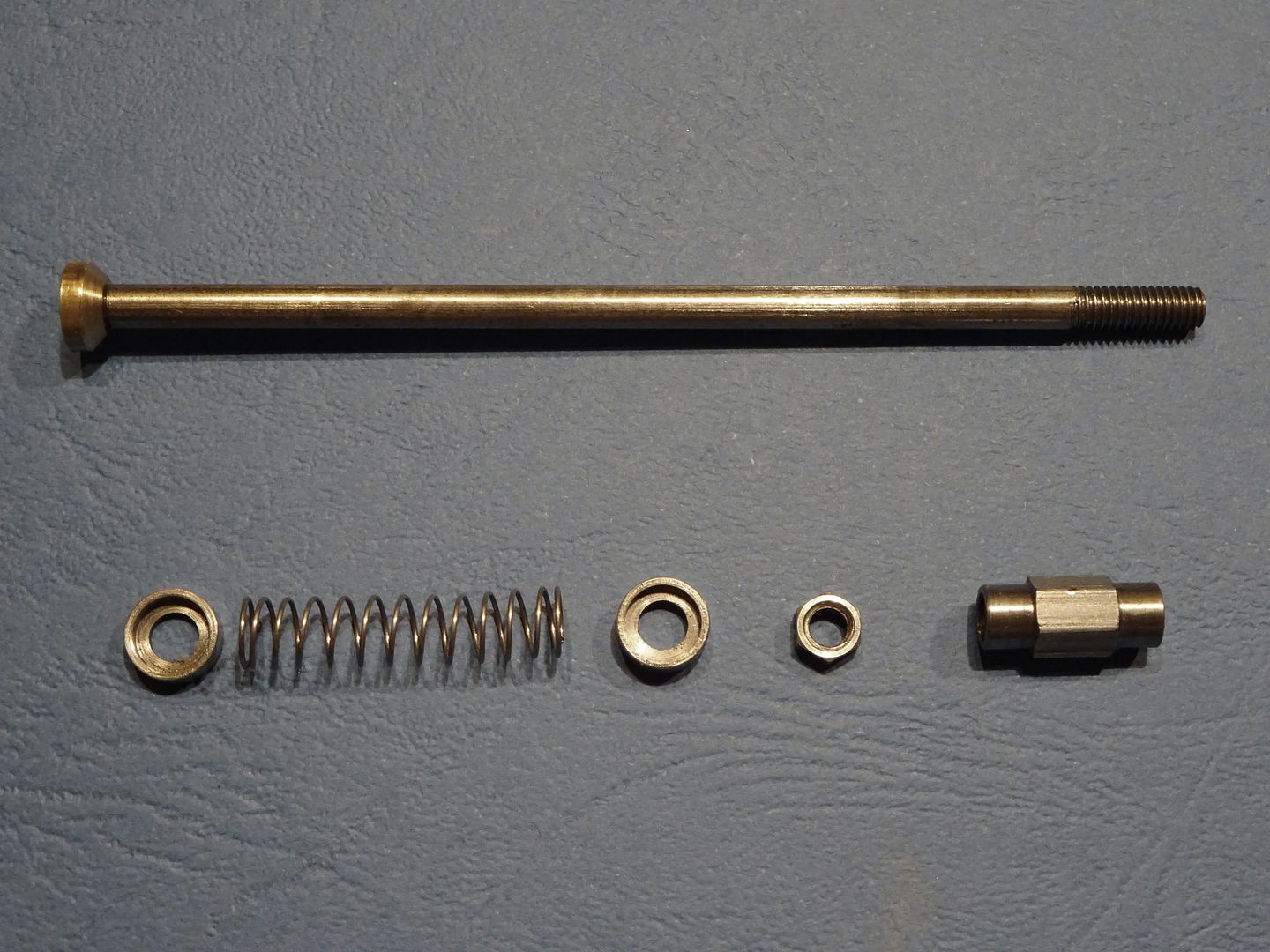
These are just lengths of 303 Stainless steel faced off to there respective lengths. Thread one end of each M4 x 4mm long for the valve head and the other M4 x 10mm long to allow adjustment of the cam follower.
Valve Heads
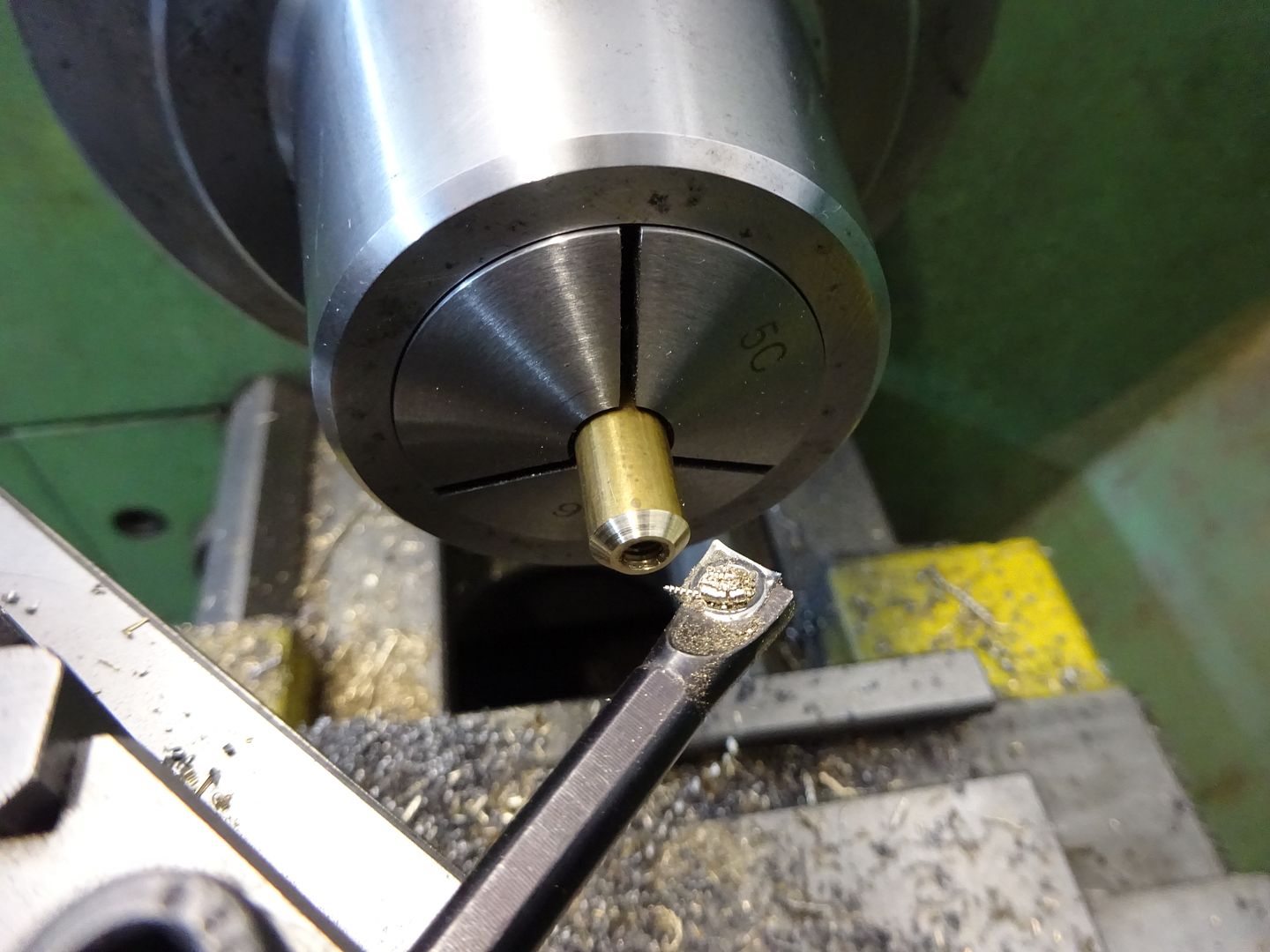
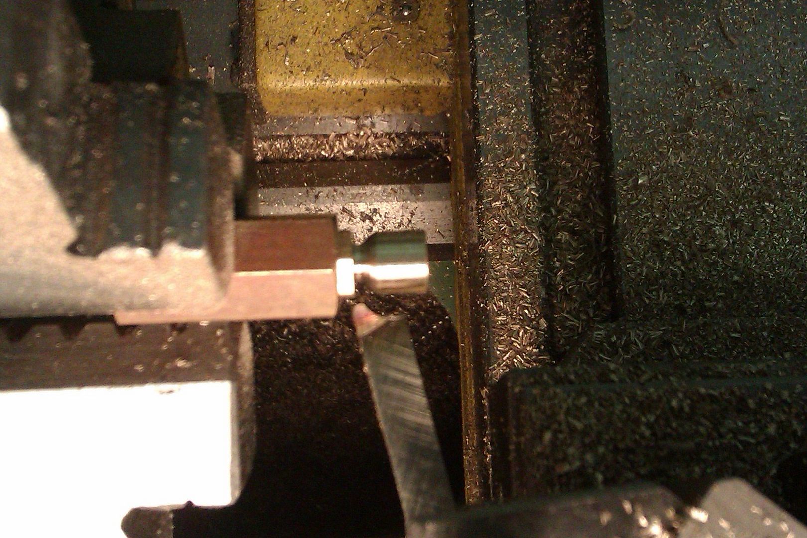
Drill and thread some 8mm dia brass M4 and then cut the 45deg seat, part off and repeat. I find it easier to use a boring bar on the rear of the work with the lathe running in reverse as its easier than reaching across the lathe to turn the topslide handle especially on a job like this where a good finish is needed if the valves are to seal. The heads should be screwed onto the valve rods with a small amount of thread lock.

Cam Followers
Face off two bits of 6mm hex steel 16mm long making sure the end that will run against the cam has a nice smooth finish. Turn down each end to 5.5mm diameter for a length of 4mm and then drill and tap M4 x 12mm deep.
Lock Nuts
These can be made from the same 6mm hex steel or you could use off the shelf M4 nuts and reduce their thickness.
Spring Collars
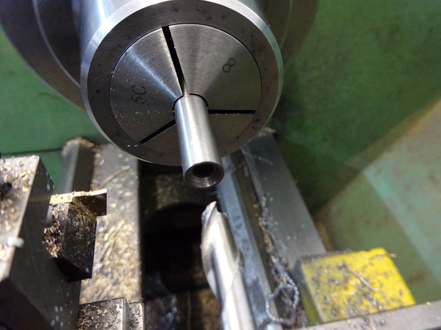
Face some 8mm dia steel, drill 4mm through and then form the recess for the spring with a 6mm milling cutter, part off and repeat for the other 3 collars.

Springs
I have a couple of boxes of assorted springs which these came from, you want quite a soft spring approx 6mm OD, 25mm free length and 0.4mm wire thickness. Just enough to keep the valve closed but not offer too much resistance as the cam compresses them.
All the above parts for one side of the engine.

Exhaust Plug
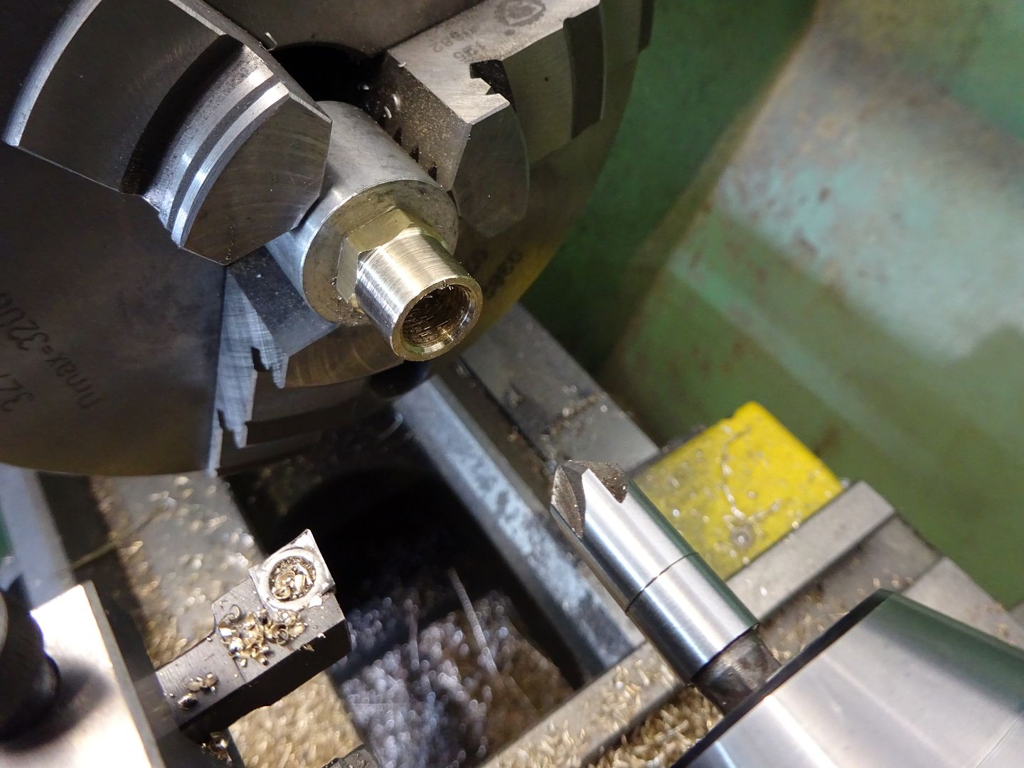
Turn a spigot on the end of some 13mm or 1/2" brass rod and thread M10 x 1 or whatever thread you used on the cylinder, part off and then clean up the head with a light chamfer to the corners.

Inlet Seat
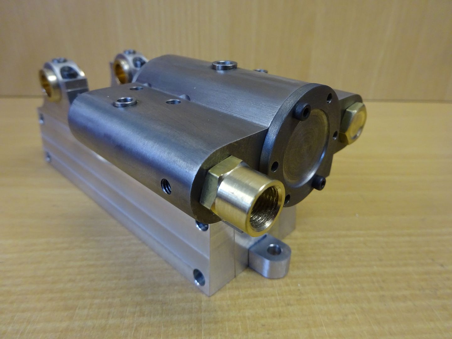
This is very similar to the Exhaust plug but should be parted off longer. Dril through 6mm dia and then open out and thread for your air/steam fitting, (1/8" BSP fits well). The bottom of this threaded hole should have a 45degree seat cut in a similar way to that of teh exhaust seat in the cylinder.

The two parts in place

J
Edited By JasonB on 10/04/2016 19:49:45
Edited By JasonB on 17/04/2016 17:20:15
17 April 2016 at 19:17 #235011 JasonBModerator@jasonb
Oil Cups
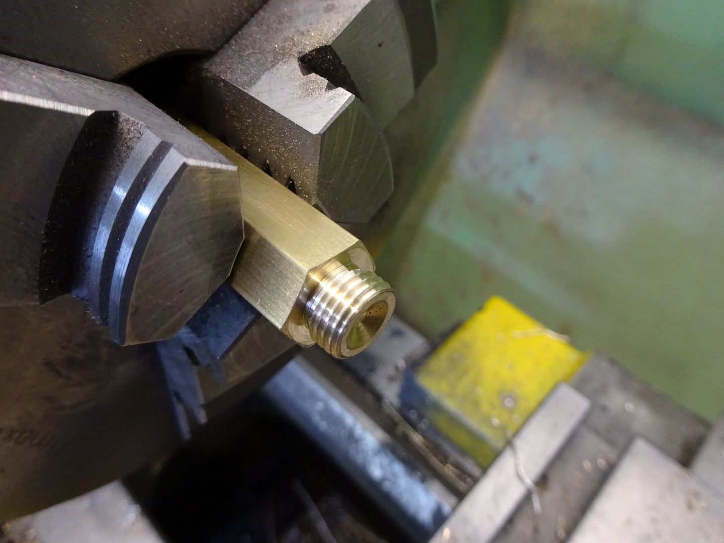
There are two sizes of oil cup but they can all be made in the same way. Start with a piece of hexagonal brass, face off and then turn and thread the spigot with a metric fine thread. At the same time drill the 1.5mm hole up through the middle then part off.
Now take a piece of scrap material and drill and thread so the embrio oil cup can be screwed into it. It worth spending a couple of mins doing a decent job as these holders will come in useful in the future, I have a range of sizes with female thread one end, male the other.
With a ball nosed milling cutter enlarge the 1.5mm hole to form the inside of the cup. Now you can either gring up a profile tool from a piece of HSS which can be used to turn down the top of the cup from hex to round and then fed in to create the neck as below. Or just use a round nosed tool the do the waist and use a file to round over the external angle blending the concave waist into the cup main diameter.

Flywheel
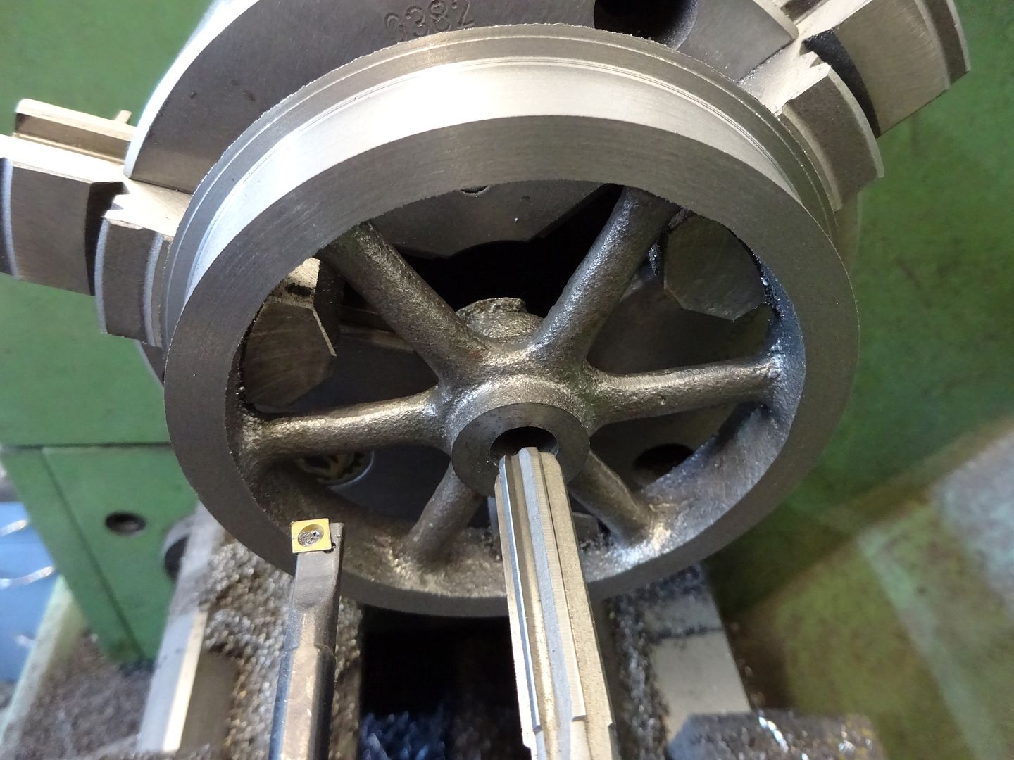
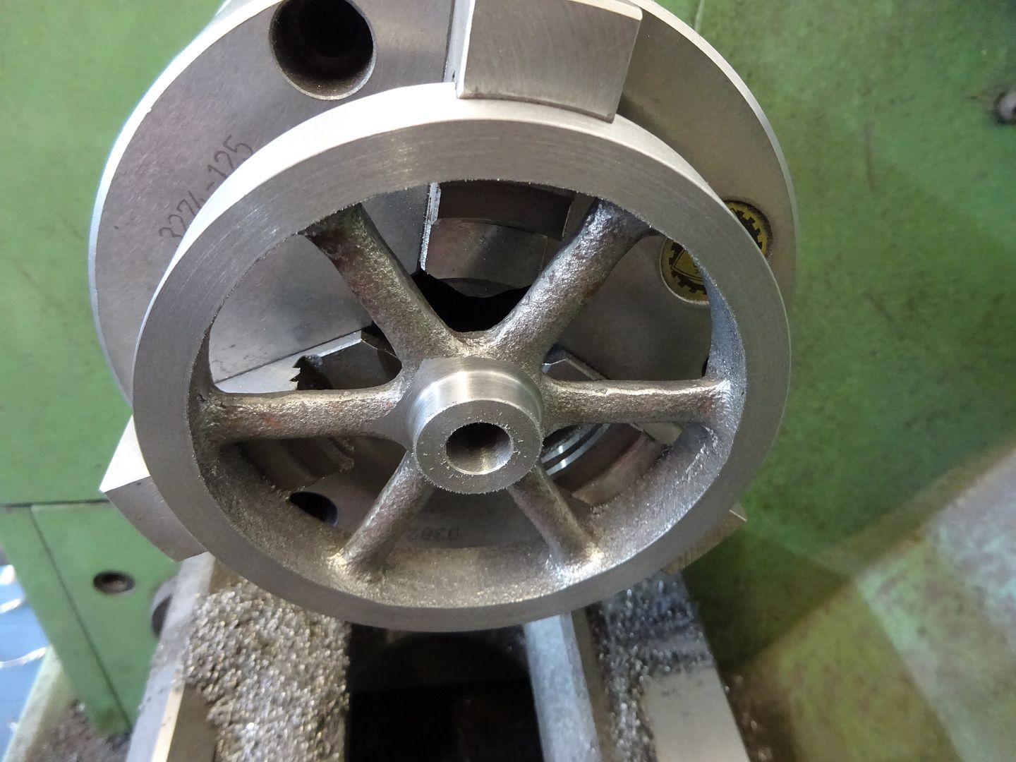
Depending where in the world you are located nominal 4" or 100mm flywheel castings sould be available, I went for a couple of "Perseus" ones from Reeves. The castings were quite nice so after a quck clean up with a file I was able to grip them by the inside of the rim using the 3-jaw chuck while the outer face and side were machined. The hub can then be faced, drilled to 9mm, bored to 9.8mm so the 10mm reamer has a true running hole to follow

The flywheel can then be held in the outside jaws while the opposite side of the rim and hub are faced off. I have shown a 18mm wide hub and 15mm wide rim but these are not critical and can be adjusted to suit your castings. The 98mm diameter does matter as much larger and they will be rubbing against the display base!

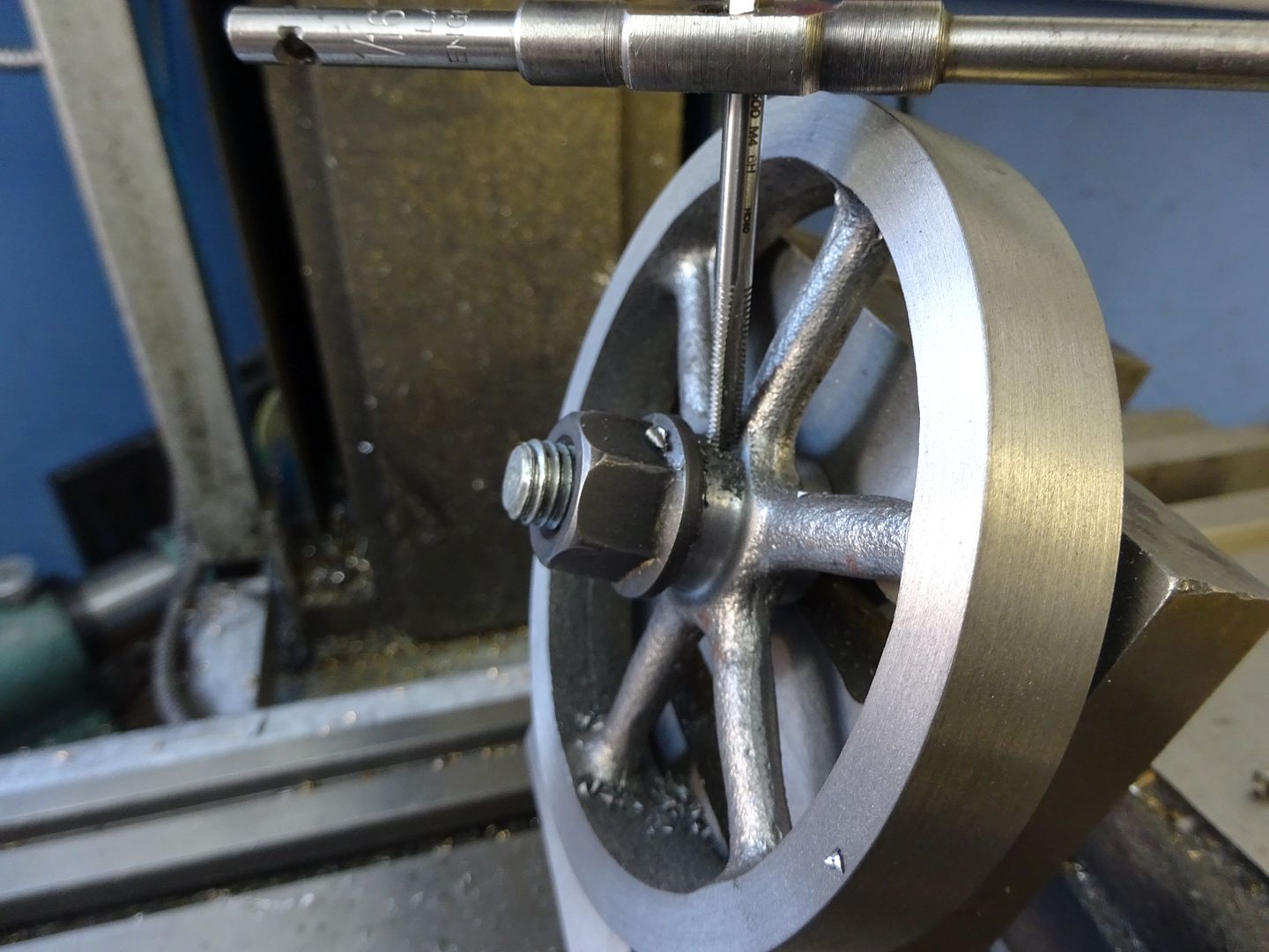
As this is a small engine that won't really do any work I opted to retain the flywheels with a simple M4 grub screw. Hold the flywheel at an angle so your drill and tap just miss the edge of the rim and drill & tap M4. A long reach ctr drill is an advantage to get the hole started. Use a sacrificial bolt through the central hole, start the tap then remove to complete threading.


All that remains is to make up a few studs for the various fixings though hex head screws could be used. One thing with metric fasteners is that the standard ones tend to look a bit flat and have a large hex which can look wrong on a period engine. I opted to use the machine turned ones that Bruce (Polly) Engineering sell as these have a smaller hex, are taller and only chamfered heavily on one face.
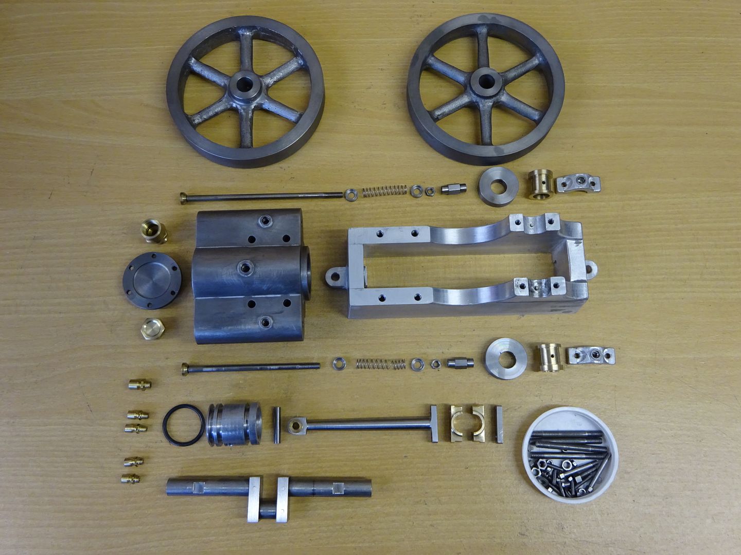
This is what I ended up with.


Oil Cup Drawing to download
Flywheel Drawing to downloadJ
Edited By JasonB on 18/04/2016 18:44:06
-
AuthorPosts
- Please log in to reply to this topic. Registering is free and easy using the links on the menu at the top of this page.
Latest Replies
Home › Forums › Work In Progress and completed items › Topics
-
- Topic
- Voices
- Posts
- Last Post
-
-
Arc Euro Trade Ltd.
Started by:
Ketan Swali in: General Questions
- 15
- 15
-
21 July 2025 at 19:15
 Grindstone Cowboy
-
Issue 4767 and links
Started by:
Andy Stopford in: Model Engineer & Workshop
- 2
- 2
-
21 July 2025 at 19:14
 JasonB
-
Pipe bending by hand versus pipe bending tools
Started by:
Greensands in: Workshop Tools and Tooling
- 2
- 2
-
21 July 2025 at 18:58
vintagengineer
-
Amadeal lathes – Any good??
1
2
Started by:
Tim Sallows in: Workshop Tools and Tooling
- 16
- 28
-
21 July 2025 at 18:58
bernard towers
-
Round Bar Bender
Started by:
Trevor Howley in: Workshop Tools and Tooling
- 1
- 1
-
21 July 2025 at 18:46
Trevor Howley
-
My vise isn’t at 90 degrees
Started by:
moonman in: Beginners questions
- 15
- 24
-
21 July 2025 at 15:41
 JasonB
-
5 inch gauge Stirling single
Started by:
Michael Callaghan in: Locomotives
- 5
- 7
-
21 July 2025 at 15:37
Michael Callaghan
-
Diving in to ATC?
Started by:
Steve355 in: CNC machines, Home builds, Conversions, ELS, automation, software, etc tools
- 4
- 11
-
21 July 2025 at 14:55
 Martin Connelly
-
Hopeless…Alibre Ass
Started by:
Nigel Graham 2 in: CAD – Technical drawing & design
- 6
- 21
-
21 July 2025 at 14:40
blowlamp
-
Edward Thomas excessive wheel slip
Started by:
Ian R in: Locomotives
- 3
- 4
-
21 July 2025 at 14:11
Ian R
-
Hofmann Rollers
Started by:
Martin Kyte in: General Questions
- 11
- 18
-
21 July 2025 at 13:07
DC31k
-
Herbert B drill information?
Started by:
Andrew Tinsley in: Workshop Tools and Tooling
- 4
- 12
-
21 July 2025 at 12:45
 Michael Gilligan
-
What’s in the archive?
Started by:
Michael Callaghan in: General Questions
- 2
- 3
-
21 July 2025 at 12:36
Michael Callaghan
-
Myford S7 VFD problem
1
2
Started by:
Glyn Davies in: Manual machine tools
- 21
- 38
-
21 July 2025 at 10:36
Glyn Davies
-
Model Engine running just off a naked flame
Started by:
 Blue Heeler
in: Stationary engines
- 6
- 18
-
21 July 2025 at 09:26
 JasonB
-
Model Engineer Magazine Collection
Started by:
mfengine1 in: Books
- 9
- 12
-
21 July 2025 at 09:22
Norman Blackburn 1
-
Panorama : Fighting Cyber Criminals
Started by:
 Michael Gilligan
in: The Tea Room
- 2
- 2
-
21 July 2025 at 09:20
Nigel Graham 2
-
Lidl castors
Started by:
 Michael Gilligan
in: The Tea Room
- 5
- 6
-
21 July 2025 at 07:30
larry phelan 1
-
Redwing Cylinder head
Started by:
Durhambuilder in: I/C Engines
- 3
- 4
-
21 July 2025 at 07:24
 David George 1
-
What Did You Do Today 2025
1
2
…
8
9
Started by:
 JasonB
in: The Tea Room
- 33
- 202
-
20 July 2025 at 21:39
Dalboy
-
Polishing compounds for stainless steel (mild abrasives))
Started by:
Simon Williams 3 in: Beginners questions
- 13
- 14
-
20 July 2025 at 20:02
 Russell Eberhardt
-
Bad design, or am I missing something?
Started by:
half whit in: Beginners questions
- 5
- 7
-
20 July 2025 at 19:16
 Julie Ann
-
Mistry dividing attachment
1
2
Started by:
Brian Merrifield in: Workshop Tools and Tooling
- 17
- 42
-
20 July 2025 at 18:43
 Tony Jeffree
-
Epoxy or acid etch primer
Started by:
Michael Callaghan in: Materials
- 1
- 1
-
20 July 2025 at 16:46
Michael Callaghan
-
Measuring a double Vee lathe bed Vee position
Started by:
Kim Garnett in: General Questions
- 11
- 22
-
20 July 2025 at 15:51
Kim Garnett
-
Arc Euro Trade Ltd.
-


