JoNo’s Pendulum

Advert

JoNo’s Pendulum

Home Forums Clocks and Scientific Instruments JoNo’s Pendulum

Viewing 25 posts - 76 through 100 (of 154 total)
  • Author
    Posts
  • #658592
    Joseph Noci 1
    Participant
      @josephnoci1
      Posted by John Haine on 31/08/2023 07:14:37:

      Well, a few points.

      First Joe, I think your Q is very respectable. Of the same order that a Synchronome has if not having to operate its count wheel. My 'Nome derivative is about 12,000, and Doug Bateman's clock is similar.

      Thanks for the encouragement…

      Looking back through this thread I don't see a mention of your bob mass. Q is defined in the simple model as "w*M/k" where w is angular resonant frequency, M the mass, and k the resistance constant. Your shape will have a lower k but mass is equally important.

      You are correct – I did not mention the weight – 3.65kg – 176mm x 72mm OD. I could hollow out the bob to a shell and fill with lead as you suggest – That can follow when I have 'perfected' the pendulum and Q becomes the limiting factor..

      Nome bobs are usually about 7kg (as is mine being a hefty chunk of CI). They are however blunt cylinders so aerodynamically not so good. If you can increase your bob density (fill it or make it from lead?) that should be a direct was to get higher Q. My tungsten bob is somewhat smaller in mass (5.2kg) but 52mm diameter rather than 80mm, and has chamfered and rounded ends. I think its relatively smaller size and high density is what gives it the higher Q.

      You plot the decay I think on a linear amplitude scale. It would be interesting to plot it on a log (ln) scale which is more natural for exponential decay. But it's fairly clear that there is a "break point" where the slope decreases. If you are seeing essentially an exponential shape it's a good indication that the loss is primarily aerodynamic – other forms of loss give different shapes. My pendulum test showed exactly such a break point, with a somewhat higher Q for that part of the decay above it. At very low speeds the loss is viscous drag which is proportional to velocity and gives the "ideal" decay shape. As amplitude increases the flow gets more complex and the loss moves towards a square-law with velocity. Douglas Drumheller in the US does a lot of work in this area and you can see some discussion at here. (By the way please feel free to join the HSN forum!) In an HSN article IIRC, Doug links this towards flow vortices detaching from the bob at higher speeds.

      I will try plotting on log scale – I use a charting tool I developed for rapid charting and analysis of data in the my days of Autopilot and flight control – excel was painful when doing repeated plots and changing scales, etc. I will try excel for this as my tool cannot do log scale plots…

      I have been reading a lot on the HSN forums, and fear that if I joined, my single join would noticeably lower the entire group's iQ…I am way below the level of the very smart folk on that site…

      I am also reaching the limits of the pendulum's environment now..

      In my setup, looking at the bob period index pulse, referenced to the GPSDO 0.5Hz reference, on a 'scope is the quickest way of seeing what the pendulum period is doing.

      After many hours of running and adjusting the weights I have it reasonably stable @ 0.5Hz with a 100us or so jitter. However, simply opening a 800mmx300mm cupboard door, 3 meters from the pendulum, causes a 3-400us jump within 1/2 a second of opening the door. The pendulum is in the study ( 2nd storey of the house..), on a thick concrete floor, but walking slowly on the floor 1 meter from the pendulum causes a similar jump – maybe motion, maybe air movement, or both. Also, I have the Atlantic ocean crashing 50 meters from the house…Perhaps Fishing would be a more successful pastime?

      Advert
      #658605
      Joseph Noci 1
      Participant
        @josephnoci1

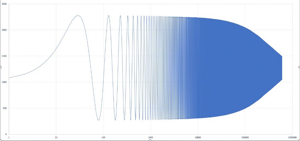
        John, Is this 'log' plot format what you mean?

        log plot.jpg

        #658630
        SillyOldDuffer
        Moderator
          @sillyoldduffer
          Posted by Joseph Noci 1 on 30/08/2023 22:06:35:

          Posted by SillyOldDuffer on 30/08/2023 20:02:58:

          At the moment the clock is 6.297933s slow.


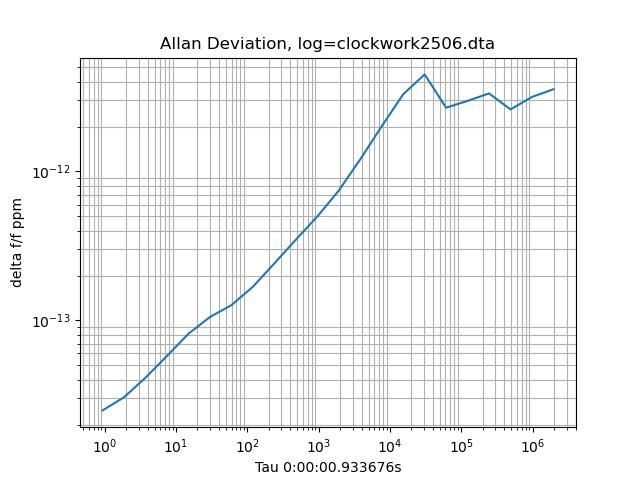
          Just for laughs here's the Allan Deviation.

          300823allan.jpeg

          Dave

          6sec in 44 days is rather impressive – 1.6us/sec slow….Not sure my approach will be as good.

          Dave, that ADEV graph bothers me – it is shown reversed to the norm, ie, starts hi and drops, stabilises and then turns up again. Also, way down below 10 minus 13…! That's good GPSDO territory and I am afraid, not possible. Even the Shortt is around 10 minus 8 @ 10 ^5 sec.

          Unless I misunderstand this curve completely, is looks like the curve you get when you do ADEV measurement on an oscillator using a time reference that is derived from the same oscillator – somewhat incestuous…doing so gives a curve that just keeps going down, almost forever – looks good, but is a lie.

          EDIT : is your pendulum running in a vacuum on this test?

          Yeah, that Allan graph bothers me too! I added the code long before the performance of the clock justified it, and strongly suspect something is wrong with my implementation. Not chased it much because other graphs show worrying about Allan is premature. There's nothing legitimate in what I've done to justify 10⁻¹². Got the bits needed to install the vacuum system, not done it yet. At the moment the bob swings uncased in air.

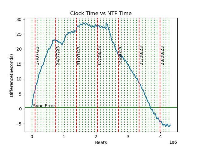
          6 seconds in 44 days would be impressive if it were consistent. Boo, hoo the graph of clock time vs NTP is less impressive because the rate wanders:

          clockvsntp3108.jpeg

          X-axis is in millions of beats, but the grid verticals are midnights, red Sundays. Sync error is the difference between clock start and NTP, another bug in my clock setting code.

          Apart from the large wander, the blue line also has a daily ripple corresponding to temperature change. I'm hoping both are due to an error in my temperature and pressure compensation system.

          I'm letting the clock run in hope more data will explain why the rate changes. Doesn't seem to have an environmental cause.

          Dave


          Edited By SillyOldDuffer on 31/08/2023 11:28:06

          #658633
          Joseph Noci 1
          Participant
            @josephnoci1

            Dave:

            One needs other hobbies when playing with pendulums, that's for sure. Everything takes a very long time – days or weeks to evaluate any changes, while the environment changes as well. In one of the papers I read , the fellow took 7 years (!) to evaluate a specific element on his pendulum. And as I said in my last post, my environment prevents me progressing further now, so short of moving home….

            #658638
            SillyOldDuffer
            Moderator
              @sillyoldduffer
              Posted by Joseph Noci 1 on 31/08/2023 08:10:22:

              Posted by John Haine on 31/08/2023 07:14:37:

              Well, a few points.

              ...

              However, simply opening a 800mmx300mm cupboard door, 3 meters from the pendulum, causes a 3-400us jump within 1/2 a second of opening the door. The pendulum is in the study ( 2nd storey of the house..), on a thick concrete floor, but walking slowly on the floor 1 meter from the pendulum causes a similar jump – maybe motion, maybe air movement, or both. Also, I have the Atlantic ocean crashing 50 meters from the house…Perhaps Fishing would be a more successful pastime?

              Or knitting!

              Don't despair, these misbehaviours are good news I think the better made a pendulum is, the more likely it is to pick up environmental events. And your monitoring system is detecting them.

              Houses aren't particularly stable, even concrete ones. I'm hard put to find a good place for my clock. At the moment, it's on a 1st floor window sill on an external cavity wall (breeze blocks). The clock and wall catch the sun in the afternoon, and I'd be surprised to find the wall isn't moving due to thermal changes. The room has a wooden suspended floor and walking on it upsets the pendulum slightly: I try to keep out of the room. The wall is parallel and to and only 3 metres away from a narrow residential road, light slow traffic only, but vibration is detectable.

              The rest of my home is even more unstable plus there's a clumsy cat! Understairs is a possibility, but people crash about on the stairs. Bathroom and kitchen are out – too wet and busy. Workshop full of vibrating tools. Dining room busy. Far corner of living room is a possibility, hidden behind the visitors only sofa, except I do have visitors. Downstairs toilet is a maybe too – I could lock the door! I've thought of using 3 big concrete sewage pipes on end to sink a shaft in my back garden, putting the pendulum on a concrete block at the bottom.

              I don't have to worry about the sea, but what's the tidal range on your beach? Several parts of the UK foreshore sink noticeably when the tide comes in – millions of tons of water push the geology down, and the ground springs back when the tide goes out. Lots of energy in big waves too!

              There's no end to the torture. You detect a slight problem with a pendulum clock and find you have to move house to fix it.

              surprise

              Dave

              #658648
              Joseph Noci 1
              Participant
                @josephnoci1

                So why do we do this?

                #658649
                duncan webster 1
                Participant
                  @duncanwebster1

                  To quote JFK, because it's hard.

                  It keeps the grey cells going, both those who are actually doing it, and we who merely look on in awe.

                  #658676
                  Joseph Noci 1
                  Participant
                    @josephnoci1

                    Its making my grey cells grey..

                    I have difficulty in coming to grasps with this : if the pendulum amplitude is kept truly constant, what does the period do if the pendulum rod grows in length?

                    #658681
                    S K
                    Participant
                      @sk20060
                      Posted by Joseph Noci 1 on 31/08/2023 18:25:40:

                      Its making my grey cells grey..

                      I have difficulty in coming to grasps with this : if the pendulum amplitude is kept truly constant, what does the period do if the pendulum rod grows in length?

                      It depends on where and how you are measuring the amplitude, doesn't it? If you are using an angular sensor at the top, then it doesn't know anything about the length, and if the length of the rod grows, the pendulum will slow down.

                      If you are measuring the amplitude as the peak swing in X at the bottom, then longer length also means slower. To do this properly, the sensor for this should travel along with the pendulum, e.g. instrumented on a dummy pendulum. But most have the sensors mounted to the pendulum's support, which will typically shift in space independently of the pendulum itself as the temperature changes.

                      Even the placement of the sensors in X matters. John measured 1um position resolution of his opto. But almost any support fixing the opto's position will shift that much with a one degree change in temperature.

                      Edited By S K on 31/08/2023 19:21:05

                      #658683
                      Michael Gilligan
                      Participant
                        @michaelgilligan61133

                        Intuitively, I would say the pendulum would swing more slowly

                        … but that probably depends on how you are measuring ‘amplitude’

                        i.e. whether the notion of ‘truly constant amplitude’ refers to the angle swung, or to the maximum linear excursion of some nominal point which [say] triggers a light trap.

                        I’m struggling here … but I think the answers would be different.

                        MichaelG.

                        #658698
                        duncan webster 1
                        Participant
                          @duncanwebster1

                          Longer pendulum is longer period for the same angular swing. If you're controlling distance rather than angle, then longer pendulum is lower angle, and lower angle gives longer period in its own right.

                          I think the effect of longer pendulum is dominant, but am open to correction 

                          Edited By duncan webster on 31/08/2023 21:42:29

                          Edited By duncan webster on 31/08/2023 21:43:42

                          #658704
                          Martin Kyte
                          Participant
                            @martinkyte99762

                            M H Robert’s table in Precision Pendulum Clocks shows a loss of 1.05. mins in 24 hours at 6 degrees amplitude which falls to 14.8 secs in 24 hours at 3 degrees which to my understanding demonstrates that the period increases with amplitude.

                            regards Martin

                            Edited By Martin Kyte on 31/08/2023 23:25:48

                            #658707
                            duncan webster 1
                            Participant
                              @duncanwebster1

                              Martin, you're correct, looks as if I've remembered it incorrectly. This gives the expression for a large amplitude pendulum, and shows that period goes up as angular amplitude goes up.

                              If I can't think of anything better to do I'll try to add the effect of length increasing to angular amplitude decreasing for a fixed distance amplitude, but that will have to wait until tomorrow

                              #658709
                              Joseph Noci 1
                              Participant
                                @josephnoci1

                                The formulae for pend. period shows directly that period increases with length, but I am trying to understand what happens if angular displacement is kept constant all the time. When the length , or radius, increases, the distance the bob swings ( the arc length) increases for the same displacement angle. Since I am controlling displacement angle and not rate, I guess the rate must reduce.. Its nearly 2 in the morning…

                                #658710
                                duncan webster 1
                                Participant
                                  @duncanwebster1

                                  Yes, if you're controlling angle of swing, and the pendulum gets longer, the period increases.

                                  I've just realised that using optical methods on either the bob or a vane, and the edge which does the interrupting is parallel to the rod, changing the pendulum length shouldn't make any difference, you are actually measuring angle. Won't work with a spherical or other funny shape if the bob is doing the interrupting

                                  Edited By duncan webster on 01/09/2023 00:46:08

                                  #658718
                                  John Haine
                                  Participant
                                    @johnhaine32865
                                    Posted by Joseph Noci 1 on 31/08/2023 09:12:55:

                                    John, Is this 'log' plot format what you mean?

                                    log plot.jpg

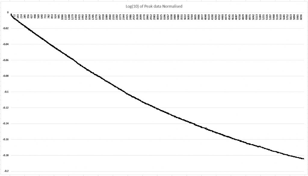
                                    No, I mean log amplitude but linear time. For each cycle take its peak, normalise to the starting amplitude, then take the log. The resulting value for pure exponential decay will be a straight line with negative slope.

                                    #658719
                                    John Haine
                                    Participant
                                      @johnhaine32865
                                      Posted by Joseph Noci 1 on 31/08/2023 08:10:22:

                                      Posted by John Haine on 31/08/2023 07:14:37:

                                      After many hours of running and adjusting the weights I have it reasonably stable @ 0.5Hz with a 100us or so jitter. However, simply opening a 800mmx300mm cupboard door, 3 meters from the pendulum, causes a 3-400us jump within 1/2 a second of opening the door. The pendulum is in the study ( 2nd storey of the house..), on a thick concrete floor, but walking slowly on the floor 1 meter from the pendulum causes a similar jump – maybe motion, maybe air movement, or both. Also, I have the Atlantic ocean crashing 50 meters from the house…Perhaps Fishing would be a more successful pastime?

                                      Joe, you are in a unique position to repeat an experiment that has only been done once! You have a pendulum in a location with regular seismic noise which is, uniquely, properly instrumented to measure its motion. Many years ago Doug Bateman noticed that the pendulum of his clock had a tiny motion even when not having been impulsed. This seemed to be due to vibration of the support point. Doug made measurements using a travelling microscope. Philip Woodward analysed the motion of a pendulum subject to random motion of the support with an important conclusion, that the main cause of error was small random changes in amplitude via circular deviation, and the effect of this increases with Q! This is unlike errors caused by internal impulse noise which are reduced by higher Q. Other than Doug's observations, to my knowledge the only other observation has been by Bryan Mumford (of the Microset) who logs the timekeeping of the courthouse clock in Santa Barbara. He saw a large transient in the period caused by an earthquake in California, and based on that a lot of horologists argue that high Q is undesirable, but no one has done proper measurements.

                                      So it would be really interesting to just turn off the impulsing, let the pendulum coast down, and log the remaining motion for as long as convenient, if the SNR of your angle sensor permits. No need for very rapid sampling either, the bandwidth of the motion is a fraction of a hertz.

                                      #658782
                                      Joseph Noci 1
                                      Participant
                                        @josephnoci1
                                        Posted by John Haine on 01/09/2023 06:57:27:

                                        Posted by Joseph Noci 1 on 31/08/2023 09:12:55:

                                        John, Is this 'log' plot format what you mean?

                                        No, I mean log amplitude but linear time. For each cycle take its peak, normalise to the starting amplitude, then take the log. The resulting value for pure exponential decay will be a straight line with negative slope.

                                        Ok, I think I have plotted it correctly –

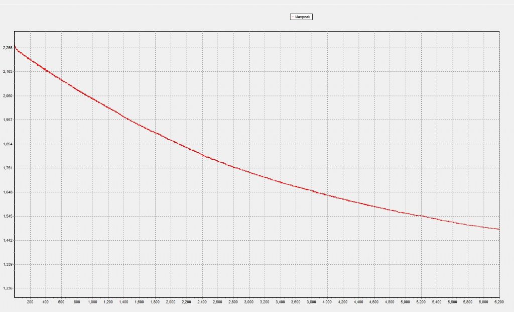
                                        This is a plot of Log(10) of normalised data:

                                        Not exactly a straight line.

                                        log10 plot of peaks.jpg

                                        This is a plot of just the peak values – extracted from the Angle sensor output file, with peaks extracted

                                        These plots are are the same for all intents…

                                        What am I missing?

                                        plot of peaks only.jpg

                                        John, you also said –

                                        You plot the decay I think on a linear amplitude scale. It would be interesting to plot it on a log (ln) scale which is more natural for exponential decay. But it's fairly clear that there is a "break point" where the slope decreases. If you are seeing essentially an exponential shape it's a good indication that the loss is primarily aerodynamic – other forms of loss give different shapes. My pendulum test showed exactly such a break point, with a somewhat higher Q for that part of the decay above it.

                                        Where do you see the break point – in which curves? I would like to understand better.

                                        Also, which curve am I looking at to see 'essentially an exponential shape' ? The Log plot, or my straight amplitude decay curve?

                                        I am somewhat confused –

                                        As my log plot is not a straight line, does this imply that my losses are primarily NOT aerodynamic? If so, the the losses must lie in the pivot?

                                        Or should the curve BE exponential confirming a 'good' set of mechanics, with losses mainly aerodynamic?

                                        I am not sure if what I have is good or bad, nor the reason why!

                                        #658789
                                        Michael Gilligan
                                        Participant
                                          @michaelgilligan61133

                                          I am very rusty on this stuff, Jo … but I think you might want to use the natural logarithm:

                                          **LINK**

                                          This looks like a good tutorial … I’m off to get a drop of Jura

                                          MichaelG.

                                          .

                                          Edit: __  Try here: https://serc.carleton.edu/sp/library/teachingwdata/graphsexponential.html

                                          Edited By Michael Gilligan on 01/09/2023 22:06:39

                                          #658791
                                          Michael Gilligan
                                          Participant
                                            @michaelgilligan61133

                                            Too late to re-edit that untidy post

                                            MichaelG.

                                            #658793
                                            John Haine
                                            Participant
                                              @johnhaine32865

                                              The natural log will just have the same numbers multiplied by a constant, which from memory is I think 2.302 [ln(10)] (could be wrong).

                                              Joe, could you email me the numbers behind one of the plots please? I could try to illustrate what I mean.

                                              #658801
                                              Joseph Noci 1
                                              Participant
                                                @josephnoci1

                                                John,

                                                I have emailed the angle sensor file to you – it is the one from my last Q run – Sensor sine wave output in millivolts.

                                                I changed the lateral pivots this afternoon – from the pin in V groove to pin on a hard steel flat – WIll post photos for your comments please. Did a Q run again, in prep for the 'remaining motion' test, and the Q is below 8000! So I am investigating where the new friction comes from – did not touch the knife edge setup, but fast believing the knife edge is difficult to set up properly. It is not easy to get the knife edges perfectly at right angles to the swing plane – even lying in the trough of the bearing inner race, the knife can move forward 0.1/0.2mm on one side while the other stays where it is and then the knife pivots across non aligned edges – hard to describe but alignment is a big issue.

                                                I will do your test once my Q values are back…

                                                #658817
                                                S K
                                                Participant
                                                  @sk20060

                                                  About alignment: Your effort is amazing, but I was surprised to see you have the square knife edge riding on an inside circular surface. All knife-edge setups I've seen have a knife or knives riding on one or two flat surface(s), or vice versa (as in my previous version, which was flats on knives).

                                                  Your setup makes theoretical sense, but I feel like your square shank could easily find itself miss-positioned, riding up higher than absolute bottom dead center on either or both sides (I think you have two pivots, right?), or skewed between the sides. Especially in the latter circumstance, I could imagine friction going up. You just changed from V's to flats on the other axis, so why round for your primary one?

                                                  Also, using two quite hard steel surfaces (your knife and your inner race) sounds good, but if they are close to each other in hardness, one will inevitably bite into the other. I used sapphire for the flat surfaces, and the steel knives just won't scratch it (dulling of the knives certainly can still happen, but I never got around to polishing their edges anyway).

                                                  On a different but related point, my limited experience leads me to feel that my new spring-hinge mounted pendulum is considerably more susceptible to wobble than my old knife-edge pendulum. In the latter case, the main source of wobble was flexibility of the rod (aside from obvious lifting off of the knife-anvil interface when ham-handling it), whereas the spring hinge can easily permit a certain amount of wobble by itself in addition to the rod flexing. I've felt like the spring hinge was a step backward.

                                                  Finally, something that I, at least, have been guilty of many times: presuming that this or that technique should and hence must yield superior results, followed by bafflement when it doesn't pan out. That's when the gods really start chuckling. 😉

                                                  Edited By S K on 02/09/2023 10:05:36

                                                  #658831
                                                  Joseph Noci 1
                                                  Participant
                                                    @josephnoci1

                                                    Unfortunately its not that simple – The knife riding in the curve is intentional as the capacitive angle sensor vane has to rotate around the pendulum pivot point, which is the knife contact edge. The sensor registers and van movement, which in my case must only be rotation around the pivot. Any movement of the knife on its ledge inthe swing direction is therefore a movement of the vane, indiscernible from movement due to rotation, so it registers and offset, ie, the angle sensor peak to peak measurement remains a constant, but the midpoint is offset by the amount the knife is moved.

                                                    The knife in the bearing inner race trough is an attempt to make it always sit at the lowest point, but not accurate enough.

                                                    I don't like the springs – esp two springs separated as appears to be the norm – if the annealing of both is not identical ( esp if brazed, etc), or the length of each differs slightly, or the clamp zone contact points are not the same, etc, one spring bends more than its mate, and the rod twists….

                                                    #658832
                                                    duncan webster 1
                                                    Participant
                                                      @duncanwebster1

                                                      Many moons ago there was a description of a clock in ME where the pivot was a Stanley knife blade rocking on a piece of tungsten carbide. The carbide had a scratch to encourage the knife not to go walkies. A suggested improvement was to put the blade facing upwards, fixed to the support, and the carbide on the pendulum facing down in a sort of inverted stirrup arrangement. This was to stop it collecting dust

                                                    Viewing 25 posts - 76 through 100 (of 154 total)
                                                    • Please log in to reply to this topic. Registering is free and easy using the links on the menu at the top of this page.

                                                    Advert

                                                    Latest Replies

                                                    Viewing 25 topics - 1 through 25 (of 25 total)
                                                    Viewing 25 topics - 1 through 25 (of 25 total)

                                                    View full reply list.

                                                    Advert

                                                    Newsletter Sign-up