JoNo’s Pendulum
JoNo’s Pendulum
Home › Forums › Clocks and Scientific Instruments › JoNo’s Pendulum
- This topic has 153 replies, 10 voices, and was last updated 4 October 2023 at 16:16 by
SillyOldDuffer.
-
AuthorPosts
-
16 August 2023 at 19:04 #656780
Joseph Noci 1
Participant@josephnoci1John,
From your post –
An/A0 = exp(-n*pi/Q), where n is number of periods. So if ln(An/A0) = -1, then Q = n*pi.
So An/Ao = exp(-1) = 0.6321. Count cycles until amplitude is 63.2%, multiply by pi.
your formula gives….. exp(-1) = 0.3678 ? Which would then follow that :
Count cycles until amplitude is
63.2%37% , multiply by pi.What have I missed ?
edit – Duncan beat me to it!!! NOW it is clear! I could not understand what was presented at all…
Edited By Joseph Noci 1 on 16/08/2023 19:06:18
16 August 2023 at 19:19 #656786Joseph Noci 1
Participant@josephnoci1Posted by SillyOldDuffer on 16/08/2023 18:23:38:But I suggest there are several ways in which the formula could give wobbly results! For example, when a pendulum swings through a tiny arc, how accurately can the observer judge when 50% decay has occurred? And does he know that his pendulum is following 'damped harmonic motion'.
Unless the measurement is made very carefully in the same way by all parties, I think it unwise to get excited comparing the Q of other folks pendula. However, when the same method is applied consistently by the same operator, Q is useful as a way of checking whether a modification has improved or made a pendulum worse worse.
Dave
If the formulae is scientifically derived , it is unlikely to give 'wobbly' results. Claiming that is does or can, and defending that by blaming the wobble on slackness on the part of the observer in taking measurements is hardly a defence… If you cannot take accurate, or repeatable measurements you need to question why you are doing this in the first place. The formulae will not lie if the data is sound.
What we are trying to establish here is the scientific soundness of the formulae, not people's pendulums or measurement methods.
Your emboldened paragraph above is key, but also key is to know that the pendulum that you are playing with is of useful quality ( not Q, but appropriate workmanship, design concepts, accepted pivots concepts, etc) and that you are in the ball park with practical Q values. There is no point chasing 1sec/year if your pendulum Q is 2000. If the real Q value is 15000 or 17000 is irrelevant, either is good, and so is 12000…
Q is not the Final Cut , but it gives the user a warm feeling that he can continue to the next phase.
ALSO, you state :
. And I'd expect the Q of a powered pendulum to be different from the Q of the same pendulum left to lose energy naturally.
I don't agree = Q is Q – you cannot improve the Q by 'powering' the pendulum – put it in a vacuum, a better pivot, etc, yes, but then Q will be the new Q and nothing else. In an LC oscillator , if you remove the amplifier around the resonant cct, and hit the LC cct with a pulse, and measure the ringing decay, that will give a representation of Q. Adding the amplifier to make it oscillate only puts back the energy lost in the decay, and maintains oscillation. The Q certainly did not change.
The capacitive angle sensor I made for this is ideal for amplitude measurements. I digitise the sinusoid ( to 16bits) and log it all the while – the decay of swing is seen clearly in the overall plot, and a curve fit to the peaks shows a decay level wherever you want , against number of swings at that point. You would be hard pressed to measure more accurately than that I would guess..
Edited By Joseph Noci 1 on 16/08/2023 19:23:36
Edited By Joseph Noci 1 on 16/08/2023 19:25:53
Edited By Joseph Noci 1 on 16/08/2023 19:31:34
16 August 2023 at 19:24 #656788duncan webster 1
Participant@duncanwebster1Of course this all depends on Q being constant, i.e. not affected by amplitude. I'm not sure this is a valid assumption, but my knowledge of very low speed aerodynamics is extremely lacking. Q will almost certainly be affected by whether the door of the clock case is open or closed. It's easier to push the air out of the way with the door open I think.
It would be interesting to take multiple readings during a run down test and see if Q changes.
16 August 2023 at 20:46 #656795SillyOldDuffer
Moderator@sillyolddufferPosted by Joseph Noci 1 on 16/08/2023 19:19:12:Posted by SillyOldDuffer on 16/08/2023 18:23:38:But I suggest there are several ways in which the formula could give wobbly results! For example, when a pendulum swings through a tiny arc, how accurately can the observer judge when 50% decay has occurred? And does he know that his pendulum is following 'damped harmonic motion'.
Unless the measurement is made very carefully in the same way by all parties, I think it unwise to get excited comparing the Q of other folks pendula. However, when the same method is applied consistently by the same operator, Q is useful as a way of checking whether a modification has improved or made a pendulum worse worse.
Dave
If the formulae is scientifically derived , it is unlikely to give 'wobbly' results. Claiming that is does or can, and defending that by blaming the wobble on slackness on the part of the observer in taking measurements is hardly a defence… If you cannot take accurate, or repeatable measurements you need to question why you are doing this in the first place. The formulae will not lie if the data is sound.
What we are trying to establish here is the scientific soundness of the formulae, not people's pendulums or measurement methods.
Your emboldened paragraph above is key, but also key is to know that the pendulum that you are playing with is of useful quality ( not Q, but appropriate workmanship, design concepts, accepted pivots concepts, etc) and that you are in the ball park with practical Q values. There is no point chasing 1sec/year if your pendulum Q is 2000. If the real Q value is 15000 or 17000 is irrelevant, either is good, and so is 12000…
Q is not the Final Cut , but it gives the user a warm feeling that he can continue to the next phase.
ALSO, you state :
. And I'd expect the Q of a powered pendulum to be different from the Q of the same pendulum left to lose energy naturally.
I don't agree = Q is Q – you cannot improve the Q by 'powering' the pendulum – put it in a vacuum, a better pivot, etc, yes, but then Q will be the new Q and nothing else. In an LC oscillator , if you remove the amplifier around the resonant cct, and hit the LC cct with a pulse, and measure the ringing decay, that will give a representation of Q. Adding the amplifier to make it oscillate only puts back the energy lost in the decay, and maintains oscillation. The Q certainly did not change.
The capacitive angle sensor I made for this is ideal for amplitude measurements. I digitise the sinusoid ( to 16bits) and log it all the while – the decay of swing is seen clearly in the overall plot, and a curve fit to the peaks shows a decay level wherever you want , against number of swings at that point. You would be hard pressed to measure more accurately than that I would guess..
…
I'm surprised what I said is controversial, hey ho such is life!
My point is three-fold: the formula is an approximation; it assumes the test pendulum exhibits damped harmonic motion; and results depend on the ability of the observer to measure amplitude accurately, which is hard. (Of all the ways discussed on the forum I'd expect your capacitive system to be the most accurate because it eliminates the human element!) I suggest this combination of factors creates a situation in which forum members report different values of Q.
Although the Q formula we're discussing is scientifically derived, it's simplified. Many others are in the same boat: Ohms law doesn't apply to substances with negative resistance, and it only applies to DC or pure resistances; Newton's Laws are inaccurate at very high-speeds and below Atomic scale; the standard pendulum formula is a simplification, only accurate over small arcs.
I absolutely agree Q isn't the final cut!
I disagree that Q is Q. In electronics, there is unloaded Q, loaded Q and coupled Q. An electromagnetically impulsed pendulum, or one attached to an escapement, are both loaded. More importantly, a mechanical system has more disturbances than an LC circuit. As Duncan says, opening the door of a pendulum case alters Q because the air eddies around the bob will be different. Impulsing also disturbs the pendulum mechanically, in an extreme case by whipping the rod. Therefore, so I'd expect my pendulum kicked by a single pulse to have lower Q than it would with a well-adjusted sinusoidal drive.
So I see Q-factor as a useful guide rather than an absolute measurement.
When your pendulum is running and logging data, it will be easy to calculate Q from bandwidth periodically. Try it and see how it compares with my results and the lost energy calculation. Whatever it is, I'll be amazed if your pendulum doesn't keep better time than mine.
I suspect we're only disagreeing about the size of the Q ball-park! One thing I've learned in my pendulum adventure is that measuring anything to do with precision clocks is tricky.
Dave
16 August 2023 at 21:08 #656800Joseph Noci 1
Participant@josephnoci1I disagree that Q is Q. In electronics, there is unloaded Q, loaded Q and coupled Q. An electromagnetically impulsed pendulum, or one attached to an escapement, are both loaded.
But that's the point. Q under the measured condition will not/should not change – loaded Q measured again must be the same ( or close) or else your measurement was poor.
So I see Q-factor as a useful guide rather than an absolute measurement.
I guess that's what I said? But it does not help if the method and maths are not consistent – If you want to see if your pendulum Q is in the useful range, compared to other useful 'good' pendulums, then you need to take measurements that give compatible data…
Perhaps when pendulum Q is quoted, folk need to indicate the method as well for apples to be compared. But I think this is somewhat pedantic – Most folk will understand what a run-down Q of Xthousand means….You are probably on your own if you choose different methods…
Me, I'm mostly on my own in this anyway – I have little notion of what I am doing – I am good at devising appropriate technologies to apply and use for test and measurement, but with my good data in hand I am somewhat lost with what to do with it!
What I am aiming for is along these lines –
The angle sinusoid , which so far proves to be very stable and environmentally immune, feeds a very fast comparator ( 5us propagation delay, 7ns rise and fall time) to give me a sq wave, switched at the sinusoid's zero cross. This sq wave is fed into the TDc7200 TDC chip ( Time to digital) on the stop input. The start input is fed with a 1hz pulse from my pretty stable and accurate GPSDO. The TDC gives me the delta, down to the nearest 2ns. With TIMELAB I can get ADEV directly from this data.
The angle sensor sinusoid zero cross is at BoB BDC and observing that point, and the comparator switching, referenced to the GPSDO 1hz, all on a scope, shows a jitter around that point of less than 200ns. This alleviates any issues related to opto-slot sensors and light shielding vanes, etc.. – there are none!
The pendulum drive – this is my nemesis right now but, – The angle sensor peaks are at the ends of the swing, BDC is the sinus zero point, so the drive current to the drive coil is displaced 90deg. The Nucleo takes the angle sensor sinus, and generates a drive sinus, 90deg shifted, of 'appropriate' amplitude, via a 16bit DAC, to the coil. The idea is to control the pendulum amplitude (not rate) either via that drive sinus amplitude or a combo of amplitude and phase relationship to the angle sensor sinus, both controlled ONLY by the running computation of energy loss each cycle, and NOT referenced to any time control pulse, ie, the pendulum is free running, with only lost energy being replaced. If temp and pressure and humidity compensation can be applied as well, and if the free running pendulum is stable, then I can adjust time with the balance weights, and finally just gear the pendulum time up or down to match the rest of the world's time…
post far to long – no-one reads such dissertations!
Edited By Joseph Noci 1 on 16/08/2023 21:36:59
16 August 2023 at 21:56 #656810Joseph Noci 1
Participant@josephnoci1Posted by duncan webster on 16/08/2023 19:24:11:Of course this all depends on Q being constant, i.e. not affected by amplitude. I'm not sure this is a valid assumption, but my knowledge of very low speed aerodynamics is extremely lacking. Q will almost certainly be affected by whether the door of the clock case is open or closed. It's easier to push the air out of the way with the door open I think.
It would be interesting to take multiple readings during a run down test and see if Q changes.
What do you mean by multiple readings Duncan? At which points?
Low speed aerodynamics are difficult – there is a glaring scarcity of scientific data at such low Reynold numbers – sub 10, even below 3 or 4…In aircraft wings design I worked with numbers up in the R10,000, for fighter jets, down to R1000 or so for small UAV's – there are few software tools that model correctly below R10. There are toold for liquid flow in pipes..
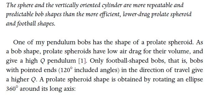
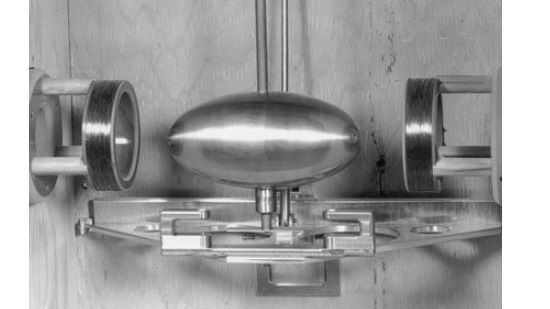
What is valid though, and contrasts with aircraft wings, is that laminar flow is not a Bob's friend. When the air sticks close to the bob, at low bob velocities, it causes the glove of air attached to the laminar layer to be dragged along, instead of being pushed aside. That artificially increases the perceived size of the bob in terms of frontal air area, and therefore drag. Cylinder bobs standing up are bad – flying saucer bob horizontal are almost as bad, vertical are quite good. Rugby balls are very good, but MUST be aligned in swing, else much worse than most. Balls are a reasonable compromise, better than cylinders.
Turbulent airflow is , as in aircraft, just bad and causes wobble of the bob. Also, a problem that aircraft don't have, the air pushed aside, now turbulent, is not displaced far away and the returning bob rides through old turbulence on its return trip..
perfection would strive to have a rugby ball shape, polished mirror finish, so that laminar flow is encouraged, with a small ring around each nose of the ball ( position and size of ring critical, or course), called a trip – as the airflow reaches nice laminar conditions, the trip breaks that flow so that the air detaches from the bob surface and flows smoothly past the bob.
This is used on aircraft as well, esp really fast ones, to break the air from the wing – friction is reduced , sometimes up to 30%, lift can be increased by up to 15-20%, and during high angle on attack, stall can be delay by 4-5degrees. all for a piece of wire…
Edited By Joseph Noci 1 on 16/08/2023 21:57:13
17 August 2023 at 04:17 #656827 Michael GilliganParticipant@michaelgilligan61133Posted by Joseph Noci 1 on 16/08/2023 21:08:21:
[…]
The idea is to control the pendulum amplitude (not rate)
[…].
I admit that much of what you wrote went way over my head …
But those few words are ‘music to my ears’
.
MichaelG.
17 August 2023 at 09:49 #656845duncan webster 1
Participant@duncanwebster1Posted by Joseph Noci 1 on 16/08/2023 21:56:54:Posted by duncan webster on 16/08/2023 19:24:11:……
It would be interesting to take multiple readings during a run down test and see if Q changes.
What do you mean by multiple readings Duncan? At which points?
……
I meant what John H posted above, which clearly shows that Q is not constant, so for consistency across different penduli we should stick to an agreed percentage run down.
I'm awaiting your ultralow speed wind tunnel to optimise bob shape. Mine's cylindrical, axis vertical. Next one will be rugby ball passing into large diameter air cored drive coils. I wish I understood magnetic circuit design!
17 August 2023 at 10:32 #656850Joseph Noci 1
Participant@josephnoci1Posted by duncan webster on 17/08/2023 09:49:29:I'm awaiting your ultralow speed wind tunnel to optimise bob shape.
Don't exist…With all the associated compromises, these sorts of tests are normally done in water with dye injection, and then they try to extrapolate to air and compensate for viscosity, etc – Most times you get as accurate an idea by blowing your pipe smoke into the clock case and watching the smoke.
A neat way is also to have a smoky flame from below, and orient the bob vertically for a rugby ball bob, for example, with the smoke hitting center of bob point. Video the smoke/air flow to capture the vortex, and play back slowly and compute the air speed from the distance traveled by the smoke in 1 sec, etc. Use a hotter flame for faster, or cooler for less..and then clean up the mess.
Edited By Joseph Noci 1 on 17/08/2023 10:38:48
17 August 2023 at 11:01 #656853duncan webster 1
Participant@duncanwebster1I once worked on machines which ran in high vacuum. Despite very high velocity, the Reynolds numbers were very low. Inspection department were keen to use water flow testing on some components as it was a lot easier than messing about with vacuum. As a fairly junior engineer I was despatched to Lucas factory in Burnley to tell them as little as possible about what was a sensitive project. When I told their boffins what the R number was, the meeting wrapped up immediately, they stated that using a fluid whose density was orders of magnitude higher than real life had no chance of success. Lucas at that time were big into gas turbine combustion systems, so they had a lot of expertise. Due to catastrophic management the company no longer exists. I did get a tour round the works, where they had amongst other goodies an old submarine in use as a pressure test chamber, and an enormous reciprocating compressor used to pump it up/down, can't remember which.
17 August 2023 at 18:27 #656892S K
Participant@sk20060flying saucer bob horizontal are almost as bad, vertical are quite good.Why would the vertical vs. horizontal orientation of a same-shaped bob matter? I've always wondered why saucer shaped bobs hang vertically, when that requires the alignment to be perfect, while horizontal has no alignment problems.
22 August 2023 at 09:13 #657430Joseph Noci 1
Participant@josephnoci1Posted by S K on 17/08/2023 18:27:31:flying saucer bob horizontal are almost as bad, vertical are quite good.Why would the vertical vs. horizontal orientation of a same-shaped bob matter? I've always wondered why saucer shaped bobs hang vertically, when that requires the alignment to be perfect, while horizontal has no alignment problems.
Sorry for the belated response – problem with these topics sometimes – they pop off the stack so quickly and then are forgotten till news is worthy of publishing again…
In a pendulum where local air is becoming the limiting factor, bob shapes play a significant role. A vertical saucer presents the same aerodynamic shape while swinging in an arc ; when fitted horizontally, the air flow over the top will tend to break away from near midway on the upper surface and becomes turbulent in the bob's wake. That increases drag, induces wobble, and the bob has to return through that still turbulent air. The air on the bob underside suffers similarly, except slightly reversed and somewhat reduced – the leading edge section has increasing angle of attack with air breakaway, and the resulting turbulent air washes over the trailing edge. We are talking of VERY small effects here, but significant when you are trying for short of Shortt performance.
22 August 2023 at 10:54 #657445SillyOldDuffer
Moderator@sillyolddufferPosted by Joseph Noci 1 on 22/08/2023 09:13:18:Posted by S K on 17/08/2023 18:27:31:flying saucer bob horizontal are almost as bad, vertical are quite good.Why would the vertical vs. horizontal orientation of a same-shaped bob matter? I've always wondered why saucer shaped bobs hang vertically, when that requires the alignment to be perfect, while horizontal has no alignment problems.
…
In a pendulum where local air is becoming the limiting factor, bob shapes play a significant role. …
Rawlings (in The Science of Clocks and Watches) discusses bob shape in Chapter 4 (Dissipation of Energy by a Swinging Pendulum), and DA Bateman adds a useful section in which 'The objective was to discover which shape would give the lowest air resistance for a given volume, and hence the largest Q for a given mass and density.'
In short:
- The bob should be made of a high density material such as Tungsten
- Swinging inside a case reduces Q compared with swinging in open air
- in DAB's comparative experiment
- A 3:1 cylinder was worst – Q=1845
- Next up, a sphere – Q=2946
- Best performer, a 2:1 parabolic spindle – Q=3375
My pendulum has a mild-steel cylinder bob, not a good shape and it might rust, but I plan to swing it in a partial vacuum. As my ancient vacuum pump only gets down to about 600mb, I might try to improve the shape by rounding the ends into a "cylinder with hemispheres".
Cylinders are easier to make and balance than other types, which is a practical advantage.
I guess Joe's bob shape isn't the absolute best possible. However, still hot stuff – better than a sphere, and much better than my cylinder.
I don't think Rawling's mentions polishing. I'd expect a highly polished bob to perform better than a rough one.
Dave
22 August 2023 at 14:33 #657485Joseph Noci 1
Participant@josephnoci122 August 2023 at 14:52 #657489SillyOldDuffer
Moderator@sillyolddufferPosted by Joseph Noci 1 on 22/08/2023 14:33:45:
…
I presume you have Matthys' book – it is good reading in moments of despair.
Sadly not – last time I found one for sale it was too expensive. Ought to look again, I'm often in despair! Zero progress today on anything.

Dave
22 August 2023 at 14:54 #657490 Michael GilliganParticipant@michaelgilligan61133
Posted by SillyOldDuffer on 22/08/2023 10:54:54:
.
[…]
I don't think Rawling's mentions polishing. I'd expect a highly polished bob to perform better than a rough one.
Dave
.
Whilst certainly not an aerodynamicist … I might ponder upon the not-so-humble golf-ball
MichaelG.
22 August 2023 at 15:11 #657494Joseph Noci 1
Participant@josephnoci1Well, I am sure you know why the surface is dimpled…
Also, in the same vein, the Tubercles along the edge of a (humpback) whale flipper serve a similar purpose – and make the whale flipper one of the most efficient 'wings' on the planet! AND they just grow them, without any Aerodynamic schooling…
Edited By Joseph Noci 1 on 22/08/2023 15:17:16
22 August 2023 at 15:14 #657495Joseph Noci 1
Participant@josephnoci1Posted by SillyOldDuffer on 22/08/2023 14:52:00:Posted by Joseph Noci 1 on 22/08/2023 14:33:45:
…
I presume you have Matthys' book – it is good reading in moments of despair.
Sadly not – last time I found one for sale it was too expensive. Ought to look again, I'm often in despair! Zero progress today on anything.

Dave
Perhaps not at 'any' price, but it really is worth it if you insist on playing with pendulums!
22 August 2023 at 15:42 #657497 Michael GilliganParticipant@michaelgilligan61133Posted by Joseph Noci 1 on 22/08/2023 15:11:58:
Well, I am sure you know why the surface is dimpled…
[…]
.
Yes of course, Jo, or I wouldn’t have mentioned it
… What I don’t know is how relevant it would be at “pendulum speeds” … whatever those might be.
MichaelG.
22 August 2023 at 16:32 #657505duncan webster 1
Participant@duncanwebster1Anyone know what the ideal ratio of long axis to short axis for the oblate spheroid bob is? It scales at about 2:1. And what is a 'football shape with pointy ends'. I'd expect the oblate spheroid to be a football (US version, rugby ball to Brits)
Anyone tried British Library for Matthys book?
22 August 2023 at 16:36 #657506Joseph Noci 1
Participant@josephnoci1Michael, it depends on what the Pendulist is wishing to achieve. Vacuum tops it all, and then shapes and dimples are moot.
I have some odd 'standards' or limits I wish to abide by, and I feel using a vacuum is not allowed. So if the aim remains to achieve really good performance, then it is very relevant indeed. Since losses in air amount to over 90% of pendulum loss of mechanical energy, assuming a decent pivot, any % gained in reducing air resistance is a boon.
Those Tubercles on the whales flipper are working at very low speeds and have been shown to increase efficiency ( by measuring lift) by anything up to 30%! The problem is quantification by amateurs and amateur methods and tools…Since my main field is aerodynamics I have a very good feel for this, but at these low speeds it is very difficult indeed to quantify – hence my pedantism on trying to find a reliable, quantifiable, repeatable method of measuring Q. Most folk want high q to be able to eventually 'measure' tides – I want Hi Q so I can measure aerodynamic effects and the effect on Q.
22 August 2023 at 16:50 #657508Joseph Noci 1
Participant@josephnoci1Posted by duncan webster on 22/08/2023 16:32:58:Anyone know what the ideal ratio of long axis to short axis for the oblate spheroid bob is? It scales at about 2:1. And what is a 'football shape with pointy ends'. I'd expect the oblate spheroid to be a football (US version, rugby ball to Brits)
Anyone tried British Library for Matthys book?
I would propose that it is a straight oblate spheroid, but with a missle nose type tip so that the air is separated cleanly rather than compressed and then squashed aside – but how long is a point, and where around the oblate does it start…I think just a point will do better than none.
As to ratio – I have seen proposed ( I am digging to find the reference again..) that the ellipse should fit inside a Golden Rectangle = Golden Ellipse
22 August 2023 at 16:55 #657509 Michael GilliganParticipant@michaelgilligan61133
Thanks for your wisdom, Jo
I knew about golf-balls … but they move fast
I knew about shark-skin … but that moves through water
I had missed-out on the whale flipper.
MichaelG.
.
P.S. __ for anyone interested:
https://www.startribune.com/obituaries/detail/0000362412/
Edited By Michael Gilligan on 22/08/2023 16:57:01
22 August 2023 at 17:08 #657513 Michael GilliganParticipant@michaelgilligan61133
Posted by duncan webster on 22/08/2023 16:32:58:
.
[…]
And what is a 'football shape with pointy ends'. I'd expect the oblate spheroid to be a football (US version, rugby ball to Brits)
[…]
.
.
I agree on the first part of that, Duncan … but not the second:
https://www.dimensions.com/element/american-football
MichaelG.
28 August 2023 at 23:56 #658347Joseph Noci 1
Participant@josephnoci1My initial attempt at controlling to a fixed amplitude has met with some success and promise.
I used the angle ( = amplitude) of the pendulum as given by my angle sensor as reference, phase shift that sinusoid by 90deg and feed that to the coil driver, and control the level of that voltage so that the level of the voltage from the angle sensor remains constant.
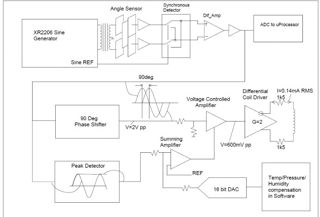
A block diagram of the electronics:
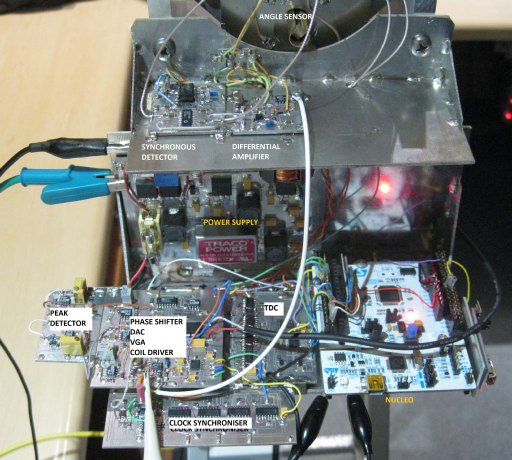
A Sine generator generates a sine wave at 5KHz and feeds a 600ohm-600ohm transformer which drives the differential angle capacitor sensor. The pickup sensor of said device is buffered and feeds a synchronous detector, driven by a reference Sine from the sine generator. The resulting DC output is amplified differentially and filtered. This resulting voltage is a representation of the pendulum angle since the senor is fitted to the pivot.
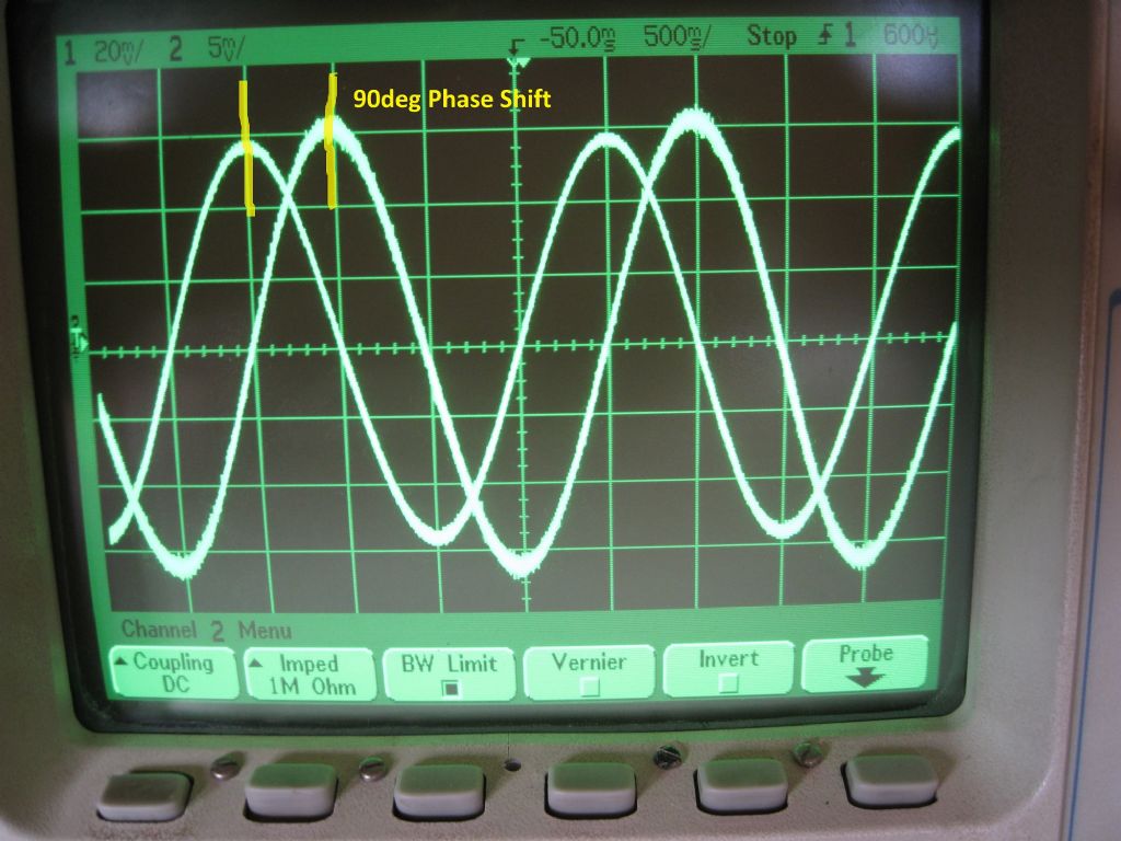
This 0.5Hz sine wave feeds an ADC read by the Nucleo processor, for later processing.The 0.5Hz also feeds a 90deg phase shifter. The shifted phase is required since the pendulum drive is via a drive coil atop the pendulum, above the pivot, and is fed with a sine wave drive per swing, all the time. The 90deg shift ensures that the sinusoidal drive voltage is at its peak when the pendulum is at BDC, and minimum when the pendulum is at the extremes of swing. There are no impulses, just a good sine wave drive, and I hope this will result in almost no pendulum perturbation.
The driving voltage level is maintained within a closed gain control loop – the pendulum angle sinusoid feeds a Peak detector, which generates a DC voltage equal to the peak of the voltage of the pendulum swing extremes. This DC voltage controls a voltage Gain Controlled amplifier. The input to the amplifier is the 90deg phase shifted sinusoid, and the output is that sinusoid, level controlled , to ensure that the pendulum swing angle is maintained. An increase in angle( amplitude) increases the Peak detector output and the VGA gain is reduced, reducing the drive sinusoid voltage to the pendulum drive coil. Reduction of swing is a reduction of the DC output of the Peak detector, causing an increase of Gain in the VGA, and increased drive to the pendulum coil.
The RMS current in the drive coil is 0.14mA when the loop is stable. The angle sensor Peak to Peak voltage output for a 2 deg total pendulum swing is 2 volts PP. This voltage varies by less than 0.2mV over 3 hours with the loop stable.
The drive voltage from the coil driver is 1.2V PP, and feeds the 10ohm coil via 3000ohm series resistance.The Peak detector output is summed with the output from a 16bit DAC. The DAC output will be used to provide a voltage offset to the VGA, causing an increase or reduction of the swing amplitude. The intention is to perform temp/pressure/humidity compensation is software, and to feed corrections via the DAC to the VGA.
Presently there is no microprocessor control at all. There is a Time to Digital convertor that measures the time in nanoseconds from the rising edge of a 0.5Hz reference pulse from my GPSDO, and the rising edge of the pulse from the pendulum BDC sensor ( an opto interrupter). This will be used to Phase lock the pendulum to the GPSDO 0.5Hz pulse initially, by control of the DAC, breaking the Peak detector loop. When phase locked to the GPSDO reference, the uP will
log the variation of DAC control voltage to maintain lock, as well as logging Ambient temp, pressure, Humidity, bob temp, and rod temp.I hope to find a way to implement some sort of amplitude compensation using all that data as reference input, at which point the pendulum will be released again and be free running, with only the amplitude loop controlling it, and the uP performing environmental corrections only.
The phase shifter is also able to be voltage controlled. If the amplitude control of the coil drive voltage does not achieve the control required ( since period is largely independent of amplitude) then the VGA loop will control amplitude, and the DAC will be used to adjust the drive voltage phase, allowing a lag or lead drive voltage to slow or speed up the swing.
A lot of electronics and a lot to experiment with….quite enjoyable.
Starting some logging now to see how the phase lock to GPSDO performs, and now that the ADC is in place, I want to do a few run-down swings to try calculate Q…
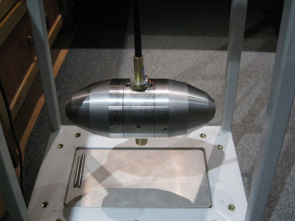
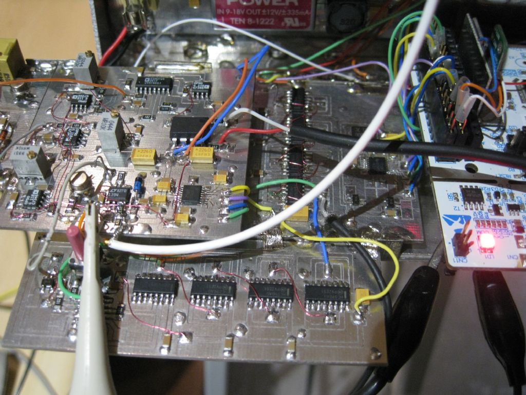
Some photos of the the growing electronics.
Edited By Joseph Noci 1 on 29/08/2023 00:06:05
-
AuthorPosts
- Please log in to reply to this topic. Registering is free and easy using the links on the menu at the top of this page.
Latest Replies
Home › Forums › Clocks and Scientific Instruments › Topics
-
- Topic
- Voices
- Posts
- Last Post
-
-
High tensile M6 bolts
Started by:
nevillet in: Materials
- 3
- 3
-
10 April 2025 at 09:58
 JasonB
-
Myford 254S Lead screw lever issue
Started by:
alan1b in: Help and Assistance! (Offered or Wanted)
- 3
- 4
-
10 April 2025 at 08:16
alan1b
-
Re-Visiting My Stuart Victoria
Started by:
Steve Withnell in: Work In Progress and completed items
- 2
- 2
-
10 April 2025 at 08:00
Diogenes
-
Motor bearings and more
Started by:
 Sonic Escape
in: General Questions
- 4
- 4
-
10 April 2025 at 06:34
Diogenes
-
Use horizontal mill as saw for metal?
Started by:
ell81 in: Beginners questions
- 16
- 17
-
9 April 2025 at 23:13
 Dave Halford
-
Steam pressure using thermistor
1
2
Started by:
michael howarth 1 in: General Questions
- 16
- 39
-
9 April 2025 at 22:59
duncan webster 1
-
Potential new society in North Yorkshire
Started by:
cliff almond 1 in: Model engineering club news
- 6
- 8
-
9 April 2025 at 22:49
Nigel Graham 2
-
N Devon Model Engineers, is this the end?
Started by:
Engine Builder in: Model engineering club news
- 10
- 12
-
9 April 2025 at 22:45
Nigel Graham 2
-
Hello
Started by:
tbm in: Introduce Yourself – New members start here!
- 3
- 3
-
9 April 2025 at 20:07
noel shelley
-
Good quality Jewellers screwdrivers.
Started by:
Andrew Tinsley in: Workshop Tools and Tooling
- 8
- 12
-
9 April 2025 at 16:51
 Robert Atkinson 2
-
Small type Reilang oil gun
Started by:
john fletcher 1 in: General Questions
- 1
- 1
-
9 April 2025 at 16:49
john fletcher 1
-
Half Scale 1/4HP A J Weed Engine
Started by:
 JasonB
in: Stationary engines
- 4
- 13
-
9 April 2025 at 16:45
 JasonB
-
Building Bernard Tekippe’s Precision Regulator
Started by:
Chris Raynerd 2 in: Clocks and Scientific Instruments
- 3
- 4
-
9 April 2025 at 15:12
Chris Raynerd 2
-
DIY Pendulum Timer – GPS-Synced Beat Analyser
1
2
Started by:
Chris Raynerd 2 in: Clocks and Scientific Instruments
- 7
- 26
-
9 April 2025 at 14:01
 Bazyle
-
DC Wasp Rebuild
Started by:
William Chitham in: I/C Engines
- 6
- 11
-
9 April 2025 at 09:40
 petetwissell
-
24cc DIESEL ENGINE FROM SOLID
Started by:
 dean clarke 2
in: I/C Engines
- 9
- 18
-
9 April 2025 at 09:37
 petetwissell
-
Autodesk Fusion Discount
Started by:
Alan Wood 4 in: CAD – Technical drawing & design
- 4
- 4
-
9 April 2025 at 09:32
 John Hinkley
-
Measuring increments on boring head
1
2
Started by:
Bill Phinn in: Workshop Techniques
- 16
- 33
-
9 April 2025 at 08:51
 JasonB
-
taper pins
Started by:
 Garry Coles
in: General Questions
- 6
- 7
-
8 April 2025 at 21:19
Nimble
-
Myford Super 7 restoration problem.
Started by:
 Bootlegger Blacky
in: Manual machine tools
- 4
- 5
-
8 April 2025 at 20:39
 Bootlegger Blacky
-
Damp proofing concrete floors
Started by:
Duff Machinist in: General Questions
- 15
- 17
-
8 April 2025 at 15:56
Chris Crew
-
Contact Details for the family of Alan Barnes
Started by:
 Neil Wyatt
in: General Questions
- 1
- 1
-
8 April 2025 at 14:05
 Neil Wyatt
-
Myford saddle lock issue
Started by:
Andrew Moyes 1 in: Manual machine tools
- 1
- 1
-
8 April 2025 at 13:16
Andrew Moyes 1
-
New member old lathe
Started by:
t1krt in: Introduce Yourself – New members start here!
- 8
- 17
-
8 April 2025 at 12:36
parovoz
-
Reader Survey
Started by:
 Neil Wyatt
in: Model Engineer & Workshop
- 14
- 24
-
8 April 2025 at 12:31
parovoz
-
High tensile M6 bolts
-
Latest Issue
Newsletter Sign-up
Latest Replies
- High tensile M6 bolts
- Myford 254S Lead screw lever issue
- Re-Visiting My Stuart Victoria
- Motor bearings and more
- Use horizontal mill as saw for metal?
- Steam pressure using thermistor
- Potential new society in North Yorkshire
- N Devon Model Engineers, is this the end?
- Hello
- Good quality Jewellers screwdrivers.


