John Wilding Regulator

Advert

John Wilding Regulator

Home Forums Clocks and Scientific Instruments John Wilding Regulator

Viewing 25 posts - 26 through 50 (of 68 total)
  • Author
    Posts
  • #125866
    Stephen Benson
    Participant
      @stephenbenson75261
      Posted by JA on 01/08/2013 10:02:03:

      I may dig out the clock this winter and continue work on it. I had not thought about using an Anchor escapement (the geometry of the pivot holes may have to be changed radically) but first I will loosen up the pivots and possibly rebush one.

      I will try to give an up-date in a few months.

      JA

      On the John Wilding 8 Day Wall Clock design you can adjust the Anchor/Recoil escapement height while it is running and it very satisfying to see the action getting better and better as you turn it.

      Steve

      Edited By Stephen Benson on 01/08/2013 10:59:03

      Advert
      #125912
      Peter Bell
      Participant
        @peterbell11509

        Hi Steve,

        Do you have any further info on the perpetual calendar + strkework for the John Wilding 8 day wall clock you refered to earlier to in the thread? Never heard of these before and cannot find much of a reference anywhere as most of my JW books are 20+ yrs old! Perhaps I have to buy a new copy of the work?

        Peter

        #125917
        Stephen Benson
        Participant
          @stephenbenson75261

          Like you I made my clock from the red book bought on ebay for a song, however I bought the latest book from Ian T Cobb which includes the additional info infact he has made the clock much simpler to make although basic time piece is pretty simple to start with it certainly makes a good first clock and the additional stuff make it very interesting for the more experienced.

          Steve

          Edited By Stephen Benson on 01/08/2013 19:35:18

          #143934
          johnp10
          Participant
            @johnp10

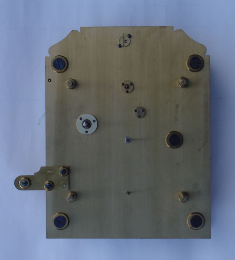
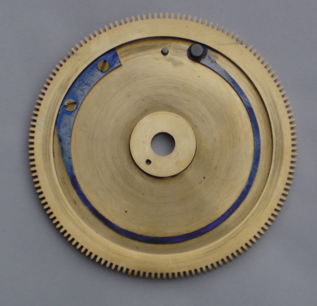
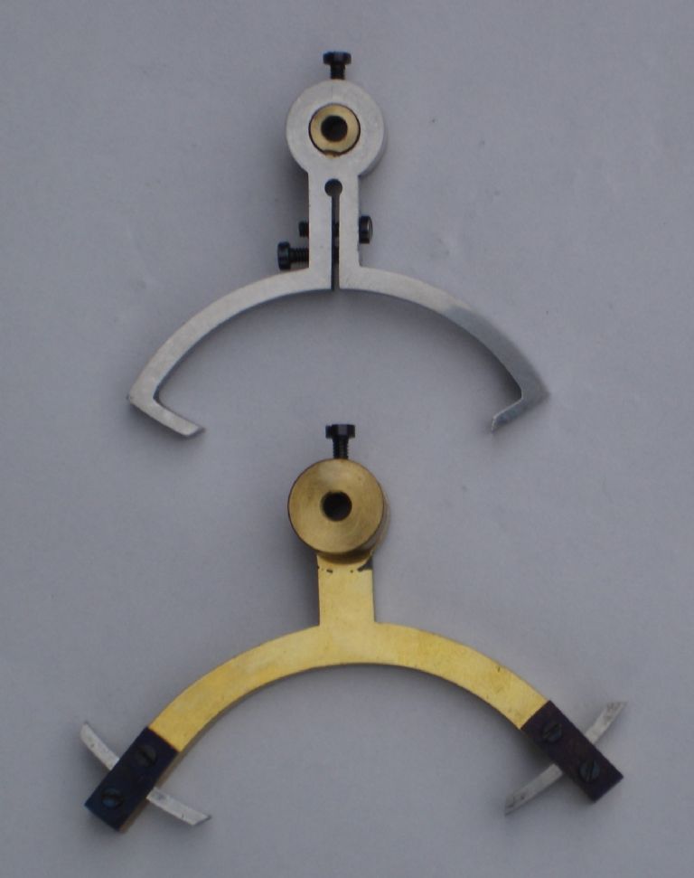
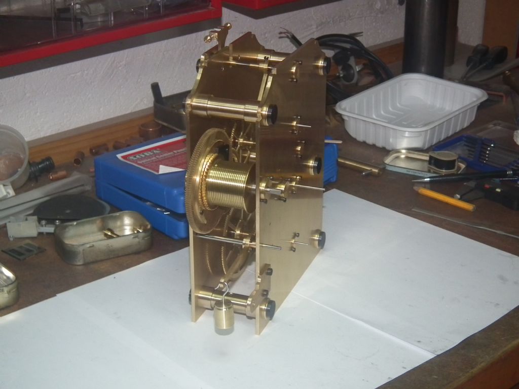
            dsc00013.jpgMaining springEscape anchorsSome time ago Mr. Russell Eberhardt posted that he intended to build the month going version of the John Wilding regulator but fitted with ball bearings at all pivot points and invited comment from anyone who had built this clock.

            In 2002 I built the eight day going version of this clock as described in Mr. Wildings book except for the maintaining power spring (q.v.) I had no problems building this clock and it kept time to two or three seconds a week on a 5lb driving weight. At a later date I added jewels to all pivots except for the hour hand arbor ,as this carries no load, and the winding barrel arbor and front pivot of the centre arbor as no jewels were available for these points. At the same time I replaced the solid escape anchor with the Vulliamy type.These modifications enabled the driving weight to be reduced to 4lb with the same time keeping.

            A couple of years later I built the same clock for a friend but this time with an escapement anchor spanning seven and a half teeth as I had read in the literature that a `Square` escapement spanning seven teeth was the optimum form of the dead beat escapement. This clock gave the same performance but required a six lb driving weight.

            After reading the discussion of Mr. Eberhardts proposal I fitted ball bearings to the winding barrel arbor and the front pivot of the centre arbor.. These are flanged shielded bearings. The winding barrel arbor bearings were 0.5" o/d and 0.25" i/d and a light push fit in the frame plates and retained with collars and 10 B.A screws and the centre arbor bearing was 6mm o/d and 3mm i/d and made a light press fit in the frame plate I first tried the ball bearings as supplied and then with the grease flushed out but could detect no difference in the pendulum swing. I then ran a drop of clock oil into each bearing as an anti-corrosion measure.These modifications enabled the driving weight to be reduced to three and a half lb.and the time keeping was unaffected.

            May I offer the followings comments on the month going version for consideration.

            Ball bearings are cheap and easy to fit. The jewels in my clock were imported from `The Swiss Jewel Company` in the U.S.A who have a minimum `shipping` order of 100$ which makes the price prohibitive unless more than one clock is being built, as in my case. The maintaining power spring in my clock is gauge plate 18 s.w.g.(0.048) thick and 0.070 wide. As the stiffness of this spring increases as the cube of its width it would not need to be much wider to suit the increased weight needed to drive the month going version and would be much simpler than Mr. Wildings bolt and shutter arrangement. The pin at the top of the great wheel in the photo limits the relative turning of the maintaining ratchet to the great wheel to four teeth, which is adequate and avoids over-stressing the spring.

            For anyone building the clock from Ball bearingsscratch, cutting the winding barrel right handed would cause the driving weight to move away from the pendulum as the weight descends as originally intended and may permit the fitting of some sort of stop-work which is absent form the present design.

            I hope that these comments are helpful to any future constructors of this regulator.

            John Parslow

            #143986
            Stephen Benson
            Participant
              @stephenbenson75261

              Thanks for the update it was very interesting

              #143990
              JA
              Participant
                @ja

                Thanks John. I have made a note of your modifications for when I revisit my regulator later this year.

                JA

                #143991
                Ady1
                Participant
                  @ady1

                  For the clock people who like to read there's a dvd with 67 old books for less than a tenner(including postage) on a well known site

                  Comes from the USA, search for, Horology CD DVD

                  Mine came in about 10 days

                  Edited By Ady1 on 15/02/2014 11:12:40

                  #144006
                  Stephen Benson
                  Participant
                    @stephenbenson75261

                    One thing is clear that the law of diminishing returns applies my Wilding weight driven 8 day recoil escapement timepiece with standard pivots is accurate to 15-20 seconds a week that figure would half if it had some sort of maintaining power.

                    Weight driven timepieces and clocks are inherently accurate as they have a stable power source (gravity) getting a spring driven clock to less than 10 seconds a week is more difficult and this where you need a deadbeat, fusee, bearings and maintaining power.

                    Edited By Stephen Benson on 15/02/2014 14:55:03

                    #144677
                    johnp10
                    Participant
                      @johnp10

                      Regarding the negative coefficient of expansion of invar, one could make the pendulum partly of invar and partly of brass. Without knowing the coefficient of expansion of either material it would be a case of trial and error to find the correct length of brass to compensate for the invar negative coefficient of expansion.

                      John Parslow.

                      #152032
                      Russell Eberhardt
                      Participant
                        @russelleberhardt48058

                        Makng some progress at last. I now have all the wheels and pinions fitted to their arbors and mounted in ball bearings with bushes in the plates.

                        I'm about to start on the pallet assembly to the Valliamy pattern. JW's book quotes 2° for the impulse angle and shows how to lay out the pallets using an impulse circle of 1.21" rad. I drew this up in a CAD program and found that using an impulse circle that big gives an impulse angle of 2°. There is a copy of that drawing here

                        I've found that, in order to acheive a 2° impulse angle I have to reduce the impulse circle to 1.03". That seems to be a big change. Has anyone else noticed this problem or have I made an error?

                        Russell.

                        #172882
                        Russell Eberhardt
                        Participant
                          @russelleberhardt48058

                          It's a while since I gave a progress report.

                          Well, first I noticed a mistyping in the above post, an impulse circle of 1.21" radius gives a 2.7° impulse angle not 2°. That was my problem. I decided to use a 1.03" impulse circle, giving the correct impulse angle and it seems to work O.K. At least, using Valliamy pallets it will be easy to change if I have made an error.

                          The movement is pretty well finished:

                          dscf2619.jpg

                          All arbors other than the bolt and shutter maintaining work are fitted with stainless steel ball bearings.  Just have to make the dial and hands. I will make the dial by photoetching. I have tried out the process making the beat plate and after several trials I think I have got the parameters right. Just trying to pluck up the courage to try it on the dial.

                          I found that Invar is very expensive here in France so I have made thee pendulum rod from a unidirectional carbon fibre composite. That material has a very small negative temperature coefficient which will compensate for the suspension, the bob, and the short length of threaded rod for the rating nut. The transition from the carbon fibre rod to the threaded rod was made 30 mm below the centre of the bob which should give the correct compensation.

                          I have added a few more photos to my album.

                          Russell

                          Edited By Russell Eberhardt on 18/12/2014 11:24:48

                          #186109
                          johnp10
                          Participant
                            @johnp10

                            Hello Russell,

                            How`s progress on the Wilding regulator? Have you finished it yet?

                            If so, it would be interesting to know what driving weight is required and what standard

                            of time keeping has been achieved. As previously stated mine is fitted with ball bearings to the winding drum

                            and the front bearing of the hour shaft. all the other bearings are jewels and it runs on 3.4 lb driving weight

                            and keeps time to about a couple of seconds a week.

                            Your clock looks very nice in your posted `photo.

                            Kind regards.

                            John Parslow.

                            #188568
                            Russell Eberhardt
                            Participant
                              @russelleberhardt48058

                              Sorry I missed your post earlier John.

                              No, the clock isn't finished yet. Very little progress since the last post due to other priorities.

                              I have tried running it using the maintaining work and it runs fine with half the weight specified in the book. I haven't made the weight pulley yet but I should be able to try it out with a single drop and check the weight required.

                              Regards

                              Russell.

                              #190458
                              Russell Eberhardt
                              Participant
                                @russelleberhardt48058

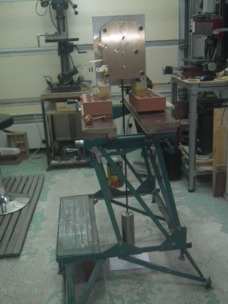
                                O.K. I've set the clock up for testing:

                                clock_test.jpg

                                The clock runs well with 4 lbs weight on a single drop so will need 8 lbs on the pulley. That compares well with John Wilding's month going version which he said needs 14 lbs. It isn't as much of an improvement as I had hoped so I thought I'd do some investigation. At least I'll be able to make the weight a bit slimmer.

                                I measured the pendulum Q factor by setting it swinging freely and counting the number of complete back and forth swings it would do before decaying to 37 % of its starting amplitude. It came out at about 1800 swings so the Q = 1800 x 2 x π = 10,000 which is about the figure expected.

                                My next test was to run with a light short pendulum (actually just 1 oz on the end of the crutch). That gave the surprising result that it would run with only 12 oz of driving weight.

                                So it would appear that the energy required to overcome friction in the movement is less than 1/4 of that required to maintain the pendulum swing. That should bode well for the timekeeping.

                                Russell.

                                #190494
                                jaCK Hobson
                                Participant
                                  @jackhobson50760

                                  There is an interesting discussion on lantern pinions vs cycloidal in Laycock's book 'lost science of John "Longitude" Harrison'. It's a short book and well written but difficult to get hold of.

                                  I think a summary of the important point is that lantern pinions have similar friction in forward and reverse whereas cycloidal has very different friction in forward or reverse. This is important if you have recoil in the escapement where the recoil drives the escape wheel in reverse. He presented an analogy of dragging an angled stick along a surface compared to pushing it along a surface – the surface friction has more impact on the push rather than the drag. However, even with deadbeat escapements, in practice the difference is still often present and significant. I think he gave an example that one often sees one of the pallet faces worn much more than the other. I remember something about the depthing on cycloidal gears is more critical to get the benefits but is often set wrong. So, since George Graham, clockmakers have favored recoil-less escapements and this is now so well accepted that that this was taught as a fundamental principal in schools. Recent trials at the Royal Greenwich Observatory suggest that a clock with lantern pinions and recoil (grashopper) escapement can perform just as well. The book is well worth a read.


                                  Edited By jaCK Hobson on 18/05/2015 18:23:23

                                  Edited By jaCK Hobson on 18/05/2015 18:26:08

                                  #190499
                                  Michael Gilligan
                                  Participant
                                    @michaelgilligan61133
                                    Posted by jaCK Hobson on 18/05/2015 18:17:48:

                                    There is an interesting discussion on lantern pinions vs cycloidal in Laycock's book 'lost science of John "Longitude" Harrison'. It's a short book and well written but difficult to get hold of.

                                    The book is well worth a read.

                                    .

                                    +1 on that, Jack

                                    Very expensive on the secondhand market too

                                    However; I am pleased to advise that Manchester Central Library holds a copy, in its reference section on Level 4.

                                    Well worth a look [at both the book and the beautifully restored library] if you happen to be in the area.

                                    MichaelG.

                                    #223307
                                    Brian H
                                    Participant
                                      @brianh50089

                                      I made this clock some time ago and generally speaking it works well and keeps time to about 10 seconds over a week.

                                      I do, however have a problem with it stopping and being reluctant to keep going when it stops but then it will keep going for the following 2 months or so.

                                      I made the weight as a long piece of brass tube with discs of Woods metal so that the total weight can be adjusted.

                                      At the moment it has stopped and it's tempting to add extra weights but I did wonder if additional weight would increase friction in the pivots and the pulley.

                                      Does anyone have any thoughts on this?

                                      #223316
                                      roy entwistle
                                      Participant
                                        @royentwistle24699

                                        Adding extra weight will lead to more friction hence wear on pivots I would make sure that the pivots and pivot holes are dead smooth and polished and not too tight mine is about 25 years old and runs on about 6 lbs ( if I remember ) and keeps time dependant on temperature because my Invar pendulum rod is not stable

                                        Roy

                                        #223331
                                        Brian H
                                        Participant
                                          @brianh50089
                                          Posted by roy entwistle on 31/01/2016 10:59:42:

                                          Adding extra weight will lead to more friction hence wear on pivots I would make sure that the pivots and pivot holes are dead smooth and polished and not too tight mine is about 25 years old and runs on about 6 lbs ( if I remember ) and keeps time dependant on temperature because my Invar pendulum rod is not stable

                                          Roy

                                          Many thanks Roy, I half wondered that, hence the question.

                                          I finished all the pivot holes using pivot burnishers and made a flat pivot burnisher from a small file withe the teeth linished off so that the grain of the linishing did the polishing.

                                          I'll try removing some weight.

                                          Edited By Brian Hutchings on 31/01/2016 12:56:06

                                          #236608
                                          Russell Eberhardt
                                          Participant
                                            @russelleberhardt48058

                                            I don't seem to be able to get much workshop time these days with all the other pressures on my time. It's nearly a year since I poste my last update so it's time for another.

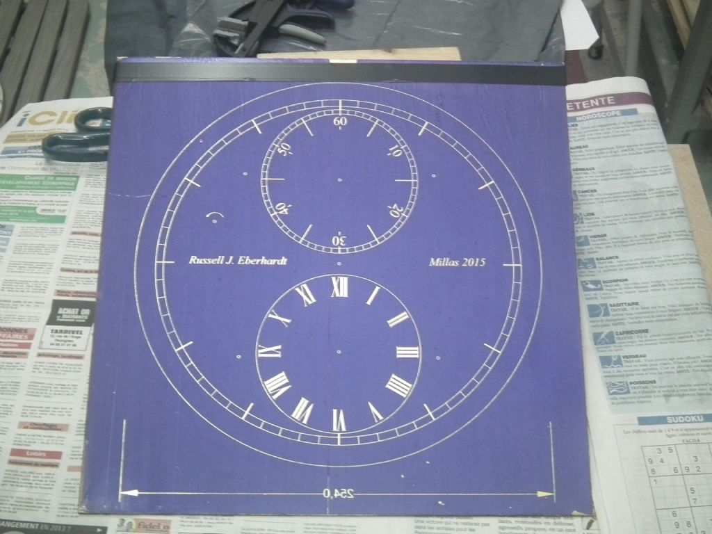
                                            About a year ago I had the movement test running propped up on some bricks on a Workmate. My next task was to make a dial. I drew up the dial in reverse on Draftsight and printed it out on Xerox transparent film in two parts as it is too big for my A4 ink jet printer. I found the inkjet printer in photo mode gave a better result than my laser printer. The two parts were lined up using printed registration marks and cut and joined. I then laminated some dry film photoresist onto a sheet of brass using an office laminator and and exposed the resist to UV from the sun for three seconds (not having a light box) . After developing I had this:

                                            dscf2661.jpg

                                            I then silvered the dial using silvering powder from Honiton Clocks and lacquered it with shellac. All the above required numerous experiments to get the process right.

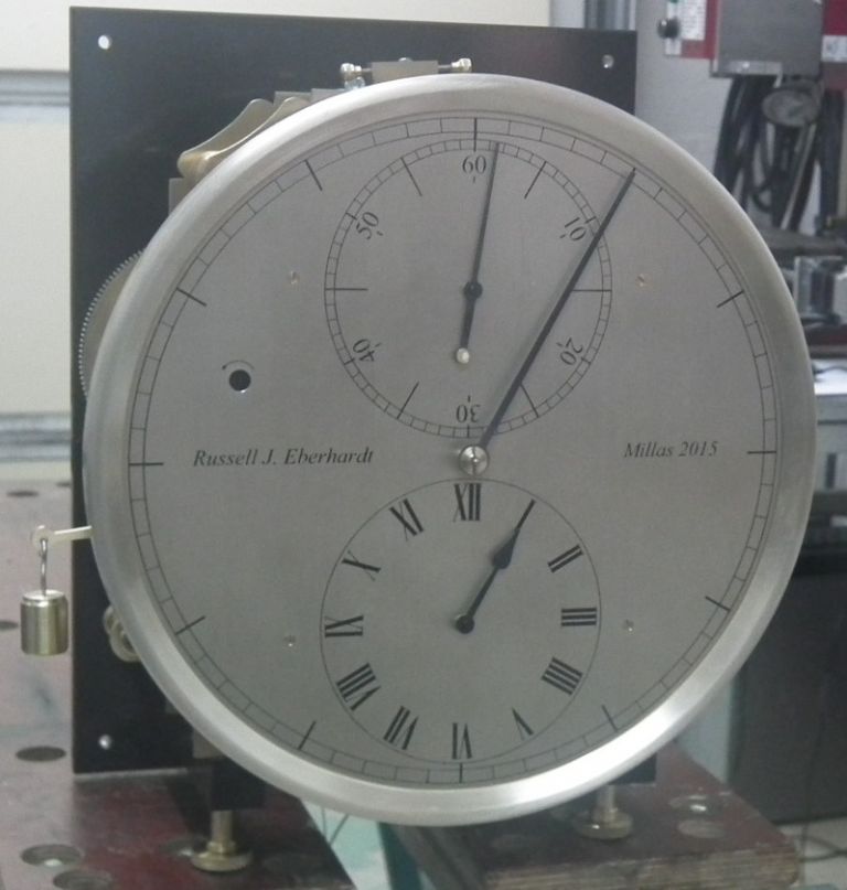
                                            Then it was just making the hands. I intended to use my little cnc mill to cut them out but a computer failure occurred and I ended up making them by hand the traditional way. I don't think the result was too bad:

                                            dscf2666s.jpg

                                            The clock is now running and mounted on the dining room wall while I continue with the case:

                                            dscf2667sml.jpg

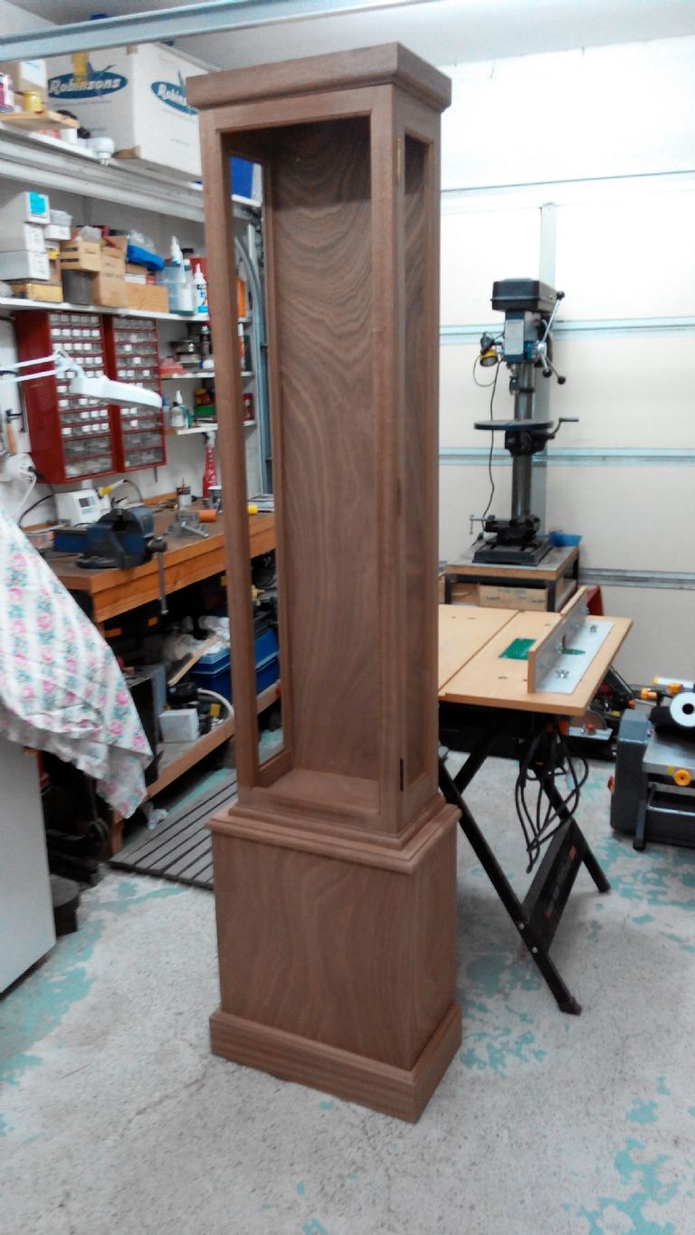
                                            I had to get the hardwood for the case shipped over from the UK ans I couldn't find a supplier here other than complete trees sawn into planks. Anyway, the case is now ready for varnishing:

                                            2016425165304.jpg

                                            Not much left to do now smiley

                                            Russell.

                                            #236611
                                            Michael Gilligan
                                            Participant
                                              @michaelgilligan61133

                                              That's looking rather fine, Russell

                                              MichaelG.

                                              #236615
                                              Ajohnw
                                              Participant
                                                @ajohnw51620

                                                That looks very good Russsell. Glad to hear that the photoresist can be exposed in the sun. I've done that with pcb's so wondered.

                                                Tempted to mention types of ball bearings but I think I will put it in the beginners clock thread.

                                                John

                                                #236620
                                                Neil Wyatt
                                                Moderator
                                                  @neilwyatt

                                                  NIce work, Russell.

                                                  Neil

                                                  #236622
                                                  roy entwistle
                                                  Participant
                                                    @royentwistle24699

                                                    Russell Well done

                                                    Roy

                                                    #236625
                                                    julian atkins
                                                    Participant
                                                      @julianatkins58923

                                                      Hi Roy,

                                                      That is a truly beautiful clock and dial and case! Wonderful work!

                                                      How did the dial surround/rim change from 'silver' to brass?

                                                      Will you add a brass sleeve to the pendulum bob?

                                                      What wood did you use for the case?

                                                      Cheers,

                                                      Julian

                                                    Viewing 25 posts - 26 through 50 (of 68 total)
                                                    • Please log in to reply to this topic. Registering is free and easy using the links on the menu at the top of this page.

                                                    Advert

                                                    Latest Replies

                                                    Viewing 25 topics - 1 through 25 (of 25 total)
                                                    Viewing 25 topics - 1 through 25 (of 25 total)

                                                    View full reply list.

                                                    Advert

                                                    Newsletter Sign-up