John Wilding 8 day Weight Driven Wall Clock

Advert

John Wilding 8 day Weight Driven Wall Clock

Home Forums Clocks and Scientific Instruments John Wilding 8 day Weight Driven Wall Clock

Viewing 25 posts - 76 through 100 (of 128 total)
  • Author
    Posts
  • #301785
    Jim C
    Participant
      @jimc

      Hi to all makers of this clock or indeed anyone who has already completed one.

      I am just in the throws of assembling the various wheels and pinions of the inners of the clock and could do with some help with the exterior motion work (hour and minute wheels) the book by John Wilding is a bit lacking in details of this assembly and whilst there are some good photographs on the forum a bit more advise and guidance wouldn't go amiss for me. This clock has truly been a challenge for me as a precision engineer but I am so close now.

      many thanks in anticipation of much superior knowledge.

      jim.

      Advert
      #301810
      Dick H
      Participant
        @dickh

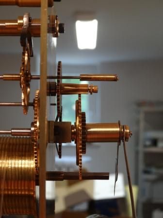
        I don´t know whether this helps but this is a side on view of the motion work on the clock as built according to the second book i.e. pinions instead of lantern pinions etc. The whole stack friction spring, minute wheel and pipe, hour bridge, and hour wheel floats on the centre arbour and is driven by the friction clutch that sits on a square that is filed in the steel collet that protrudes through the front plate. Attaching the hour bridge tensions the minute wheel against the friction spring. The minutes hand is held in place by a washer and a pin through the arbour at the end. A reverse wheel with a pinion translates and reduces the movement of the minute wheel to drive the hour wheel. In this version if you look at the clock from the front the reverse wheel stub sits at somewhere between 10 and 11 o´clock. The brass friction / bow spring is a critical bit, it is made springy by hammering and you have to adjust the tension, too slack and the hands aren´t driven and fall to the 6 o´clock position, too tight,nothing goes. The alignment of the wheels might involve the addition of a washer just to get the alignment right. The older version uses a small bridge to hold the arbour for the reverse wheel. The hour bridge´s position can be moved (big holes small screws) to centre the hour pipe.

        My clock is a bit rough and some bits are going to be remade but it´s running.

        Anybody know how to make a chapter ring which doesn´t involve too much sawing? My lathe won´t take anything bigger than 16-17 cim dia.

        Hope this helps,

        Dick H.

        dsc02406 (1).jpg

        #301866
        Jim C
        Participant
          @jimc

          Hi Dick H.

          Many thanks for the photo and description of the motion work. I am making the clock to the old book and there seems to be some minor differences to yours. I can see from the photo the friction spring and can understand now how drive is brought about by having a square on the steel collet.(no mention of this in by book !!) am I correct in thinking then that the steel collet is glued to the centre arbor? And that tension is produced between the spring with a square hole in it and the washer at the end of the arbor?

          I am grateful for your help with this and good luck with your question re the chapter ring.

          Jim.

          #301873
          Dick H
          Participant
            @dickh

            Hi Jim,

            The layout of the clock in the second book is different from that in the first. In the second version the collet is steel and also takes the centre wheel, the layouts are very different.

            I think in the first book the spring is just a push fit in the protruding bit of the collet. In the second version there is a square filed on the collet end and a corresponding hole in the spring.

            The wings/arms of the spring act on the back side of the minute wheel as a friction drive for the motion work.

            The collet is just glued / "loctited" in place.

            Hope this makes things clearer.

            Dick.

            #301918
            Jim C
            Participant
              @jimc

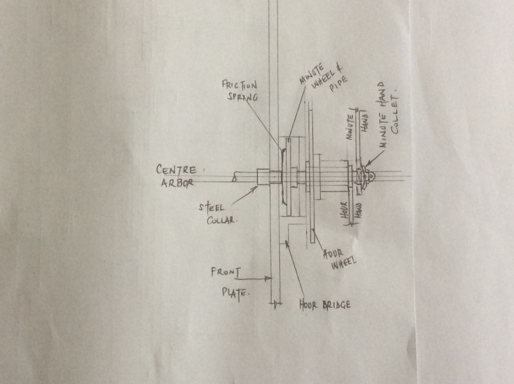
              Hi Dick, Thanks for the reply. Things seem to be falling into place now. I think I was getting mixed up with the collar on the center arbor and the collet on same arbor. Clock terminology issue here !!!!! I have drawn a cross section of how I perceive the assembly to be. Am I correct in thinking then that the hands are driven by friction from the center arbor by a sort of clamping effect between the spring and the collet. Sorry to lab our this point but it does have me puzzled somewhat. Also do Ioctite the small collar into the front plate? I will attach the drawing when I have discovered how to blush Jim

              #301919
              Jim C
              Participant
                @jimc

                Dick. Finally managed to upload drawing. Phew…img_0028.jpg

                #301934
                Dick H
                Participant
                  @dickh

                  ´Hi Jim,

                  Your drawing would appear to fit my understanding based on the second book, the collar/collet being glued to the arbour and transmitting power to the motion work via the friction spring. However in the first book it looks as if the arrangement is different. If you look at Steve Bensons photo earlier in this thread you can see a shadow of the friction spring the other way round!?.

                  I must say I´m a bit confused, I know how my clock works.

                  Having a think.

                  Dick H.

                  #302022
                  Alan Charleston
                  Participant
                    @alancharleston78882

                    Hi Jim,

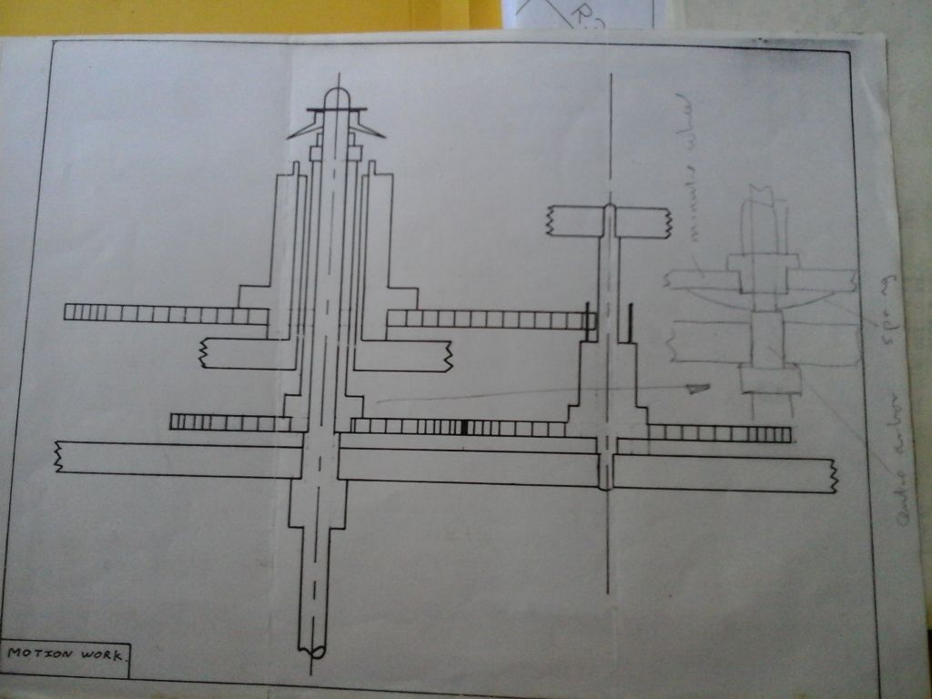
                    When I started this clock 10 – 15 years ago I was having trouble figuring out how the bits out the front worked as well so I drew up how I thought they should go and sent it off to John Wilding. He sent my drawing back with a penciled addition showing where the spring went (see photo). He didn't make any other comments so I assume my drawing is accurate.

                    I hope this is helpful. I'm not up to this part yet and I won't be until I can get the clock to run properly. I'm pretty discouraged at the moment and haven't done worked on it for the last 6 weeks or so.

                    Regards,

                    Alan C.photo0018.jpg

                    #302039
                    Jim C
                    Participant
                      @jimc

                      Hi Alan, many thanks for your help with this. It was obviously a bone of contention with you at the time. Your drawing is very clear and much more professional than my rough sketch !! And John Wilding has answered the question of where the friction spring fits. (From the horses mouth so to speak) I will crack on with this assembly then in the next few weeks to see how it all fits together. If I may I would like to offer some encouragement to you to continue with the build, especially now you have got this far. Thanks also to Dick for his input. Best regards, Jim.

                      #323687
                      Jim C
                      Participant
                        @jimc

                        Hi. I am coming to the stage of this clock build where I am trying to get it to run. I would just like to ask other owners/builders of this clock as to the size of the weight they are using.

                        I have a book which the sizes of the weight have been altered to 2" diameter by 5" long steel billet which is what I have made it too. The original sizes are 2.5" dia. by 6" long.

                        At the moment the clock won't run as is, but if I apply some finger pressure to assist the rotation of the barrel/great wheel it does seem to run for a short time them run out of steam so to speak. Could this be due to insufficient weight?

                        Hopefully clock builders out there might be able to point me in the right direction.

                        Many thanks, Jim.

                        #323774
                        Dick H
                        Participant
                          @dickh

                          Hi,

                          Depending how you read the books the answer is different.

                          Without the weight pulley the answer is about 2.2 Kg, if you have the pulley in and hence half the drop and energy the answer can be more than double this. The second book (at least) has a second roller to try and counteract the effect that the cord wrapped round the barrel wanders back and forth, this roller seems also to add a bit of resistance/friction. The ideas that the clock should rattle and a bit of oil should be present are also good. If this doesn´t work go looking for rough teeth on wheels and pinions. At the beginning it even made a difference whether I hung the other end of the cord to the left of the pulley or to the right. Left, ( viewed from the front) worked best. At one stage I found I had put the thing together so tightly that with the screws on the pillars tightened, I could stop the thing by gently squeezing the plates together with my fingers. It should rattle! If in doubt test each arbour individually. I don´t think my clock is a particularly good example but it runs. Now how about a case for it? Hope this is helpful.

                          #323817
                          Alan Charleston
                          Participant
                            @alancharleston78882

                            Hi Jim,

                            I wish you good luck with getting the clock to run. After banging my head against a brick wall for months, I finally conceded defeat and packed the bits away in a box. I probably took too long to flag it away. If you can get it to go, I'm sure you'll get a real kick out of it – but don't keep at it for too long as you'll end up feeling bloody useless.

                            I bought an old seized up Boxford lathe which I'm in the process of refurbishing. The problems are just the right difficulty for me to make them interesting but are solvable which has helped to restore my faith in myself.

                            Frankly, I wouldn't recommend anyone start the Wilding clock. He's woefully inadequate at explaining how the clock works and how to go about building it.

                            Regards,

                            Alan C.

                            #323821
                            Jim C
                            Participant
                              @jimc

                              Morning chaps and thanks for your replies.

                              Dick H – My arrangement does have the pulley so it would appear from your post that I do have insufficient weight at the moment. I will source some larger steel bar and aim more for the 8 to 9 pounds mark as suggested in the first book. If that doesn't work I will then as you suggest look for frictional resistances and free them up. I'm determined to give it a good try before admitting defeat,!!!!!

                              Alan – Many thanks for your help in the past. I'm sorry to hear that you have given the clock the elbow. I can understand your annoyance with the build notes from John Wilding. Perhaps when you have sorted out your Boxford you might dig out the box of bits and give it just one more try.

                              Thanks.

                              #323851
                              roy entwistle
                              Participant
                                @royentwistle24699

                                Any 8 day long case clock ( which is what this is ) should run on about 8lbs. I would also recommend Alan Timmins book on the long case clock.

                                Roy

                                #323855
                                Martin Kyte
                                Participant
                                  @martinkyte99762

                                  Assuming that the train is nice and free you should probably look at the depthing of the escapement and the 'beat'.

                                  It's quite a forgiving design. Do check also that the pallets are nicely polished which will help the impulse by reducing the friction in the escapement.

                                  regards Martin

                                  #323920
                                  Dick H
                                  Participant
                                    @dickh

                                    Jim C:- Before you start cutting metal, try the weight you have´, without the pulley and add some weight e.g. with a bottle of water/sand (a bit of thick wire should do to suspend it, make sure it doesn't turn and interfere with the pendulum) tagged on below your weight. By my calculations your weight is pretty much 2Kg. A drop of oil, even on the pallets? You can vary the depthing of the escapement with the eccentric at the front, start with it in the neutral position and turn slightly clockwise to make the pallets engage more. Move the pendulum by hand and listen for the tick and tock, they should be symmetric about the vertical neutral position. The clock has an adjustable crutch, i.e. you don´t have to bend the crutch to get it into beat. You can alter the position of the crutch relative to the escape wheel arbour. Conversely make sure that the tightening screw that holds the crutch in place is tight (given the moment on it, if it is slightly loose it can lead to strange effects, been there, done that)!

                                    Once it starts to run, leave it alone for a while, go have a beer or whatever. Try and see how long it goes for.

                                    Alan:- Sorry to hear of your frustration. Having taken the blasted thing apart many times to look for faults and one time even managing to put the anchor in the wrong way round I know how it can be. I messed about filing down the anchor pallets until there was nothing left and then made a second.

                                    I´ve got lots of other peoples clocks going over the years but when it came to my own….

                                    #325885
                                    Jim C
                                    Participant
                                      @jimc

                                      Hi Dick H, Alan, Roy and Martin.

                                      Thanks for all your help with getting this clock to run. I've finally got some movement from it but only for a few minutes, then it seem to run out of power.

                                      I've recently broached out the pivot holes in an attempt to make it rattle as someone mentioned. When I rebuilt it I made sure things were free to rotate and sure enough, when I put the weight on, off it went like a train!!!!

                                      I then put the pendulum on and it did carry on working but eventually stopped.

                                      There is no motion work attached at the moment, as I have been concentrating on just the train.

                                      I know there could me a multitude of reasons for it not running continuously, but any suggestions will be gratefully received.

                                      Thanks.

                                      #325898
                                      Dick H
                                      Participant
                                        @dickh

                                        Hi Jim, I don´t know how you have the movement mounted but you need to check that is in beat. You need a scale behind the pendulum rod, low down, so you can judge whether the tick and the tock are symmetrical about the neutral (i.e. vertical position). The movable collet that fastens the crutch to the arbour with the anchor / pallets on it. If the collet is not too tight you can hold the anchor with two fingers and move the crutch relative to the entrance and exit pallets. The adjustment is tiny. Listen to the tick whilst moving the pendulum slowly by hand. The kick from the escape wheel keeps the pendulum going. If you have a light clock oil, put a smidgen on the pallets. the clock has a eccentric on the pallet arbour to change the amount that the pallets engage the escape wheel. Turn it a fraction clockwise and it engages a bit more and you get a bit more kick, too much and it stops. What are you using for a suspension spring (thickness) etc.? Try a little bit more weight, once it starts to go it´s a bit like running a car in (nobody does it anymore) you are probably going to take it apart again anyway to clean it once you get it going. Regards, Dick.

                                        PS. Based on my cousin´s experiences with her grandfather clock, cat hair is lethal to the smooth running of a clock

                                        #325964
                                        Martin Kyte
                                        Participant
                                          @martinkyte99762

                                          Once you have got the beat to your satisfaction, run it untill it stops and then mark each wheel where they engage each pinion and set it going again. If it consistantly stops in the same place (one of the marks will be consistant you have idntified a tight spot.

                                          You may have stated this but is your test set up fairly rigid. If the clock does not have a stable platform you can absorb quite a lot of energy as the pendulum causes the movement to sway about so fix it down tight to a stable platform.

                                          regards Martin

                                          #325972
                                          Michael Gilligan
                                          Participant
                                            @michaelgilligan61133
                                            Posted by Martin Kyte on 08/11/2017 09:43:19:

                                            You may have stated this but is your test set up fairly rigid. If the clock does not have a stable platform you can absorb quite a lot of energy as the pendulum causes the movement to sway about so fix it down tight to a stable platform.

                                            .

                                            An excellent point, Martin

                                            My Mother's 'Vienna Regulator' kept stopping, so I cleaned the movement and set it up carefully.

                                            It ran beautifully on my bench-stand, but soon stopped again when re-installed at her house …

                                            We finally discovered that the clock case was sufficiently flexible [loose glue-joints] to 'rob' energy from the pendulum.

                                            MichaelG.

                                            #325991
                                            Martin Kyte
                                            Participant
                                              @martinkyte99762

                                              My mate Barrie was having problems with his English regulator pendulum clock. A very well mannered design. In order to effect a repair he had set it up on his clock horse which would normally have sat on the concrete in his worshop. It was however on his hall carpet. The clock ran but raising the bob had the effect of slowing the clock down and the clock speeded up when he lowered it contrary to all common sense. As a clockmaker of many years standing he was baffled. Eventually he twigged that the stand was swaying. Adding weight to the bootom of the clock horse compressed the carpet, reduced the sway and everything went back to making sense again.

                                              So even the expirienced clockmakers get caught out sometimes.

                                              regards Martin

                                              #326038
                                              Jim C
                                              Participant
                                                @jimc

                                                Hi Dick H. The suspension spring on my clock is 8 thou thick. I know the drawing call for 6 thou. but it was bought from Ian Cobb and came in at that size. Is this a potential issue ?

                                                I put a scale behind the pendulum and the swing is almost equal both sides of the centre line. If anything it is a bit more on the left.

                                                Martin and Michael. Thanks for you comments. The frame seems sturdy enough and the clock does not seem to stop in any one particular place. More to the pity !!!

                                                It just runs out of steam and does not appear to give any kick to the pendulum. Not sure where this kick is meant to come from ???

                                                i will dismantle it again and give the pivot holes another broaching. I may also harden the pallet faces, but I did make it from gauge plate which is fairly tough stuff anyway.

                                                Thanks for all your help.

                                                #326052
                                                Sam Stones
                                                Participant
                                                  @samstones42903

                                                  Hi Jim C,

                                                  My experience with clocks is quite limited, but applying basic bending theory, an eight thou suspension spring is 2.37 times stiffer than a six thou suspension spring.

                                                  Maybe that has something to do with it?

                                                  Regards,

                                                  Sam

                                                  #326060
                                                  Russell Eberhardt
                                                  Participant
                                                    @russelleberhardt48058
                                                    Posted by Jim C on 08/11/2017 17:16:58:

                                                    I may also harden the pallet faces, but I did make it from gauge plate which is fairly tough stuff anyway.

                                                    I think that may well be your problem. The impulse faces should be very hard and be well polished. A mirror finish is best. With gauge plate I would fully harden it and not temper it at all. Then polish it again. Use very little good clock oil. I just transfer a tiny drop of oil on a needle point to one of the escape wheel teeth. The movement will spread it round. Too much oil will increase the drag.

                                                    Russell

                                                    #326063
                                                    Russell Eberhardt
                                                    Participant
                                                      @russelleberhardt48058
                                                      Posted by Sam Stones on 08/11/2017 18:36:24:

                                                      My experience with clocks is quite limited, but applying basic bending theory, an eight thou suspension spring is 2.37 times stiffer than a six thou suspension spring.

                                                      Maybe that has something to do with it?

                                                      The stiffness of the suspension will slightly alter the timing by adding to the force restoring the pendulum to the neutral position. What is more important is how much friction it introduces but I doubt it would be significant. The most significant loss in the pendulum is the air resistance of the bob.

                                                      Russell

                                                    Viewing 25 posts - 76 through 100 (of 128 total)
                                                    • Please log in to reply to this topic. Registering is free and easy using the links on the menu at the top of this page.

                                                    Advert

                                                    Latest Replies

                                                    Viewing 25 topics - 1 through 25 (of 25 total)
                                                    Viewing 25 topics - 1 through 25 (of 25 total)

                                                    View full reply list.

                                                    Advert

                                                    Newsletter Sign-up