I’m interested by the decorative ‘beading’ around the cylinder ‘middle’.
How did you make that please? Two brass sections p’raps; i.e. half beading silver-soldered centrally to a length of strip & then curved round & cut to fit? Or …. ???
(I suspect that there are more cunning ways to achieve that effect!)
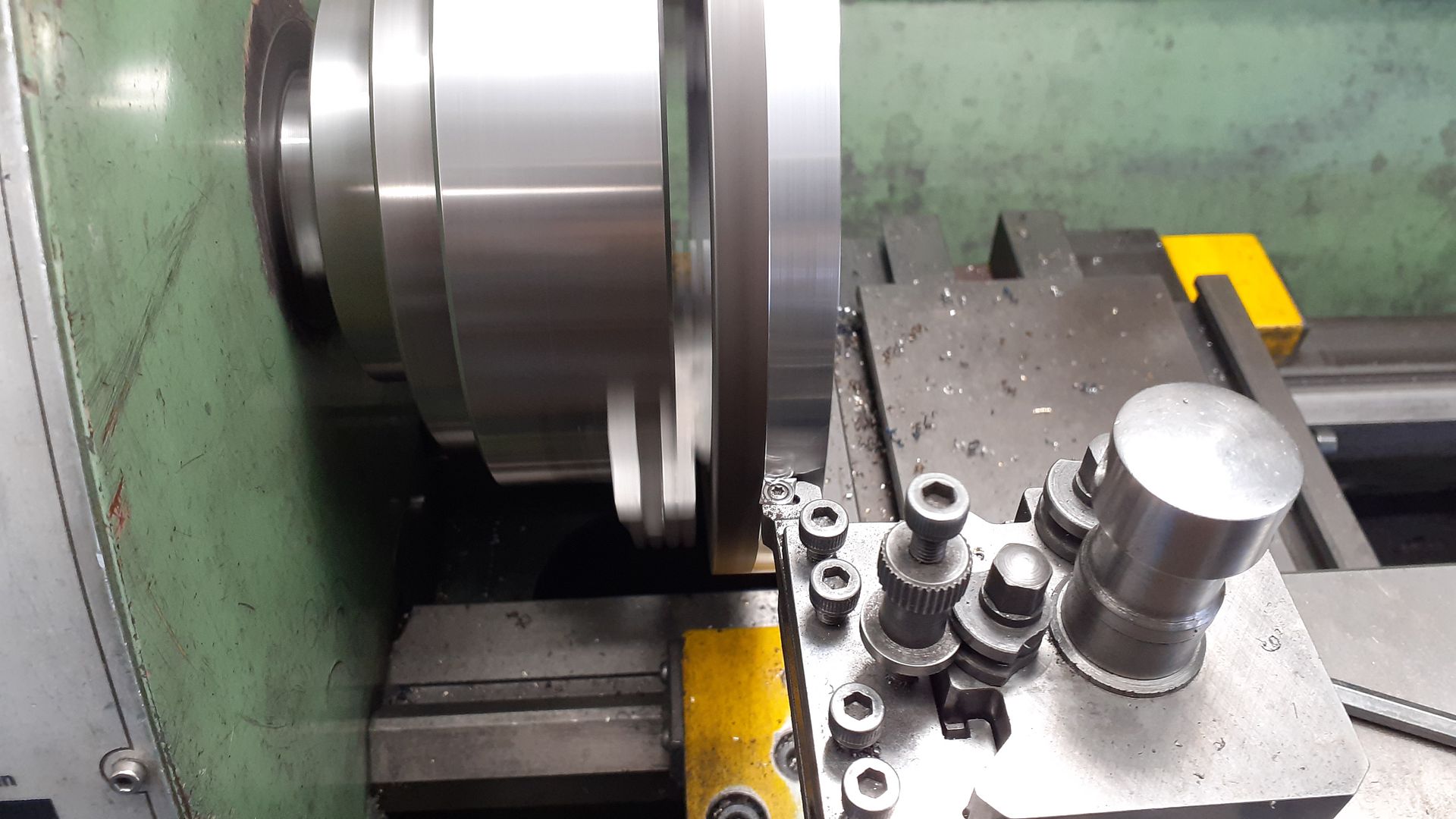
I tend to do them by turning. Face the end of a bar, bore to suit the cylinder’s OD and then with a parting tool form a squared off version of the profile as per the left image.
Then either with form tools or simply rounding over with a file against the revolving work take the corners off to form in this case the half round as per middle image
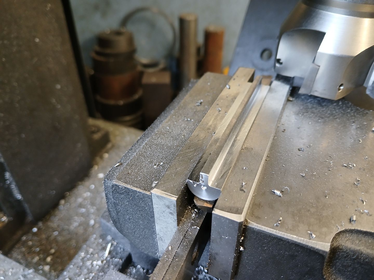
Finally part off. In this case I also milled an 8mm wide slot to clear the rectangular block that contains the steam passage to the top of the cylinder, Right image
Looks a bit like this when all soldered and machined
If you are adding them to existing cast cylinders or ones turned from solid with integral flanges then you need to cut them in two so they can be fitted, stick in place with JBWeld.
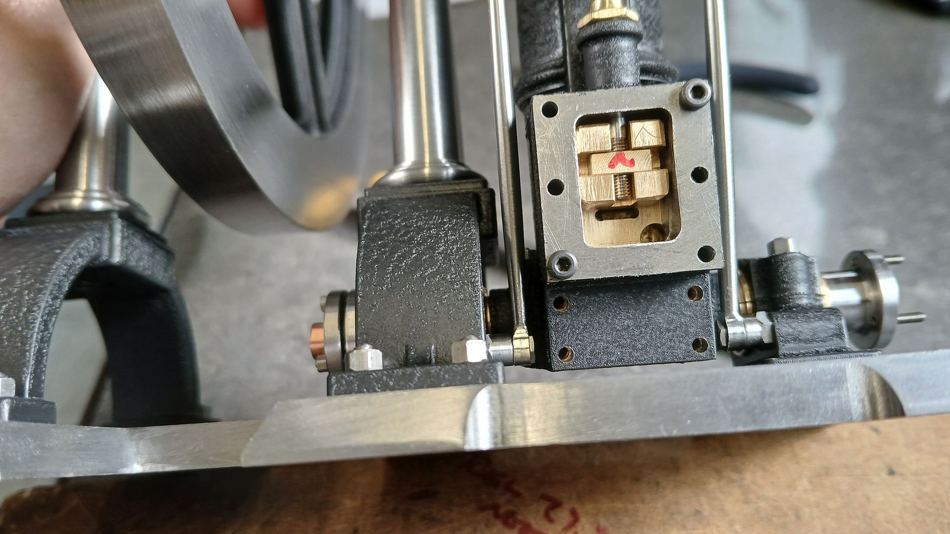
The original model had a valve chest with an integral cover and a separate gland and surround, you could also see were the passages had been drilled and plugged on the trunion below the chest. I went for the more traditional rectangular “box” and separate cover and also included a lower lip to cover the passages into the edge of the trunion.
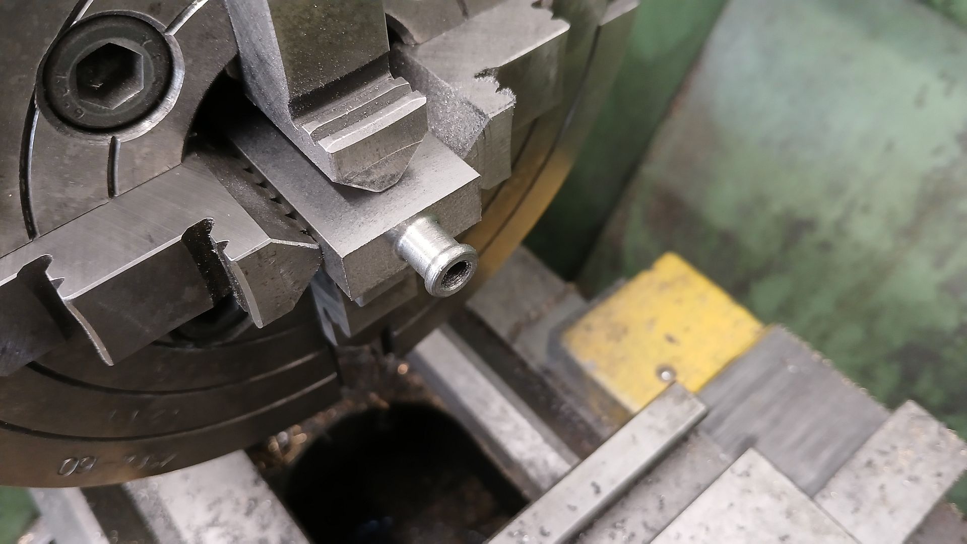
After milling a lump of cast iron down to overall size it was set up in the 4-jaw to turn the neck of the gland followed by drilling for the valve rod and tapping for the gland.
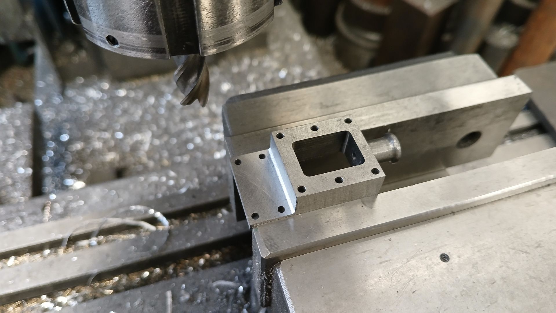
Then back to the mill to machine out the cavity, drill the stud holes and lastly mill the lip for which I used a 6mm x 1R cutter to leave a small fillet.
The remaining parts such as cylinder end cover, glands, rods, piston and valve yoke were all fairly straightforward turning with a bit of milling so I did not take photos of them but once they were made I had enough bits to give the assembly a test. No gaskets, rings or gland packing but things looked promising.
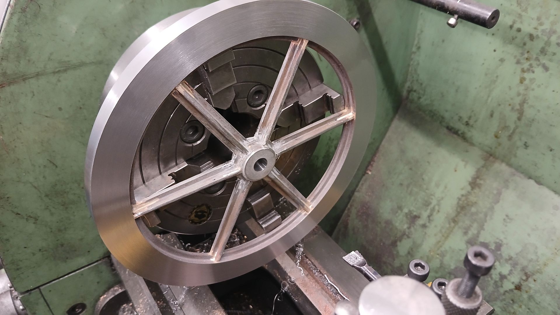
As mentioned earlier I went for a slightly deeper and wider flywheel rim to help with low speed running. The rim was turned a little oversize from some thick wall steel tube.
I opted for round stock to make the spokes, facing to length and then adding ctr drill holes at each end as I thought I might do the tapers by turning. The “+” section was machined using a face mill taking advantage of the 0.8mm tip radius to leave a fillet in the corners. After that I ended up by just holding the spokes at an angle in the vice and cut the tapers.
The outer end of the spokes were notched to fit over the web that runs around the inside of the rim. A two piece hub has slots milled to accommodate the other ends when it was sandwiched over them. I silver soldered it all together in two heats, the first to join the spokes to the rim which allowed the rim to expand and then cool without the inner end of the spokes constraining it. Then a second heat to solder them into the hub.
The rim joints filled very nicely with solder with only one needing a touch of JB Weld. The hub joints were not so close so there were a couple of gaps in the solder that needed some more JBW. On mounting the flywheel in the 4-jaw again there was a very slight movement to oval and also a slight bit of pringle going on but it only needed about 0.2-0.3mm off to get a full cut which was within what I had allowed. The hub was bored to a nice firm fit on the crankshaft and later broached for a gib head key.
That’s all my construction photos so all that is left is a video of the test run. I have taken some more photos of it being put back together after painting which should be useful for those that have shown interste in making something similar but they will have to wait until next time.
Thanks for the comments, sorry for late replay as I have been to the show.
Apart from a bit of 6mm studding and a couple of nuts and washers to hold the two halves of the hub together there was no jig. The milled slots in the hub only allowed a degree or two of wobble and there was virtually no endplay so the hub self centered. I just stepped out six divisions on the side of the rim with dividers and made the mark bigger with a sharpie so I could position the spokeY before soldering. Sorry no pics.
Yes the Pendulous description seems to suit the end pivoted action, oscillator seems better for something that pivots in the middle
I think that now that a lot more workshops have a mill the need for castings is not what it was back in the day when most only had a lathe to work with and it is a good cost saving. I would say I spent about £75 on materials for this including fixings which compares well with say a Stuart 10V or H that is double the cost and you don’t get hard bits very often in barstock and if anything is undersize then it is down to you. Cost of a muck up is also cheaper and quicker to remake. You also get a lot more workshop time for the outlay.
By way of compensation for the lack of construction photos I took a few more when putting the engine back together after painting which may be of interest to those who want to make something similar.
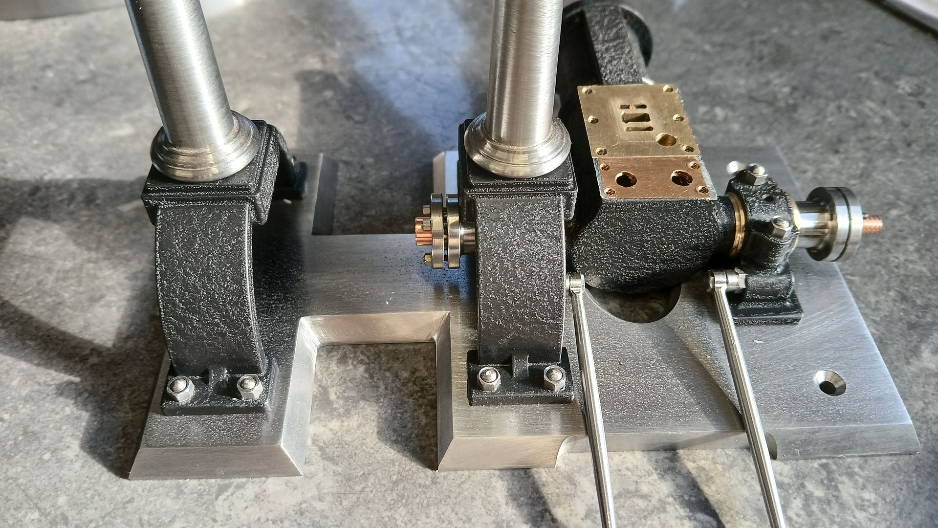
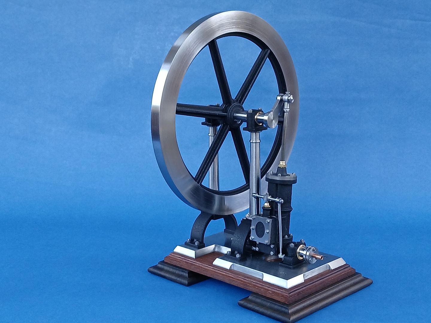
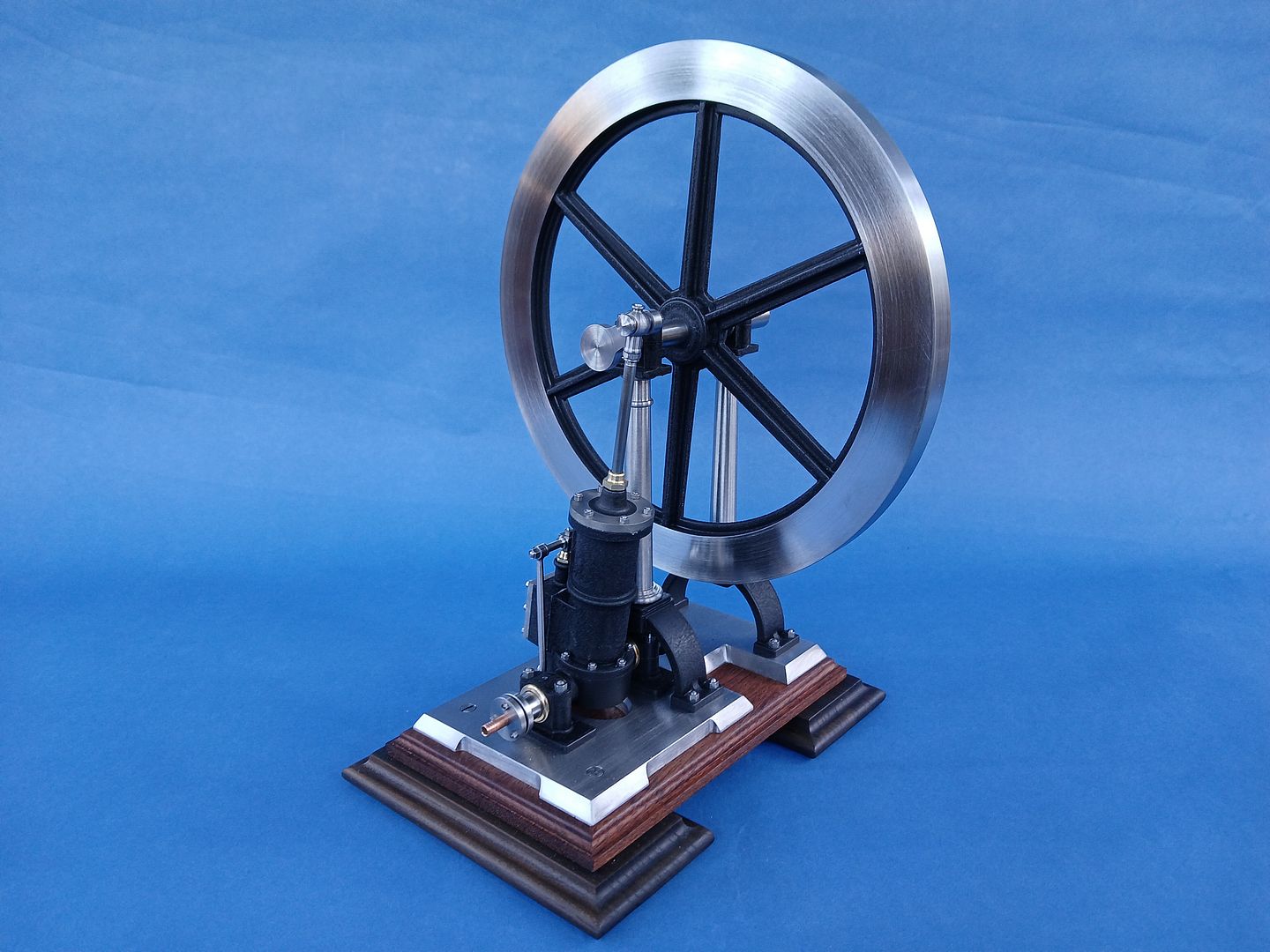
The photos in the Bonhams listing seemed to show that teh cast surfaces had some old black paint on them so I tried something new to both represent the paint and also the cast texture of the surface. A can of VHT “Wrinkle Plus” in black. This is applied in 3 heavy coats and then light heating with see the surface wrinkle. I’m reasonably happy with how it turned out, heavy coats and fine detail don’t really go well together so it is hard to get a totally even coat which means there is a little bit of difference in texture but I suppose that applies to castings and deterioration of old paint too.
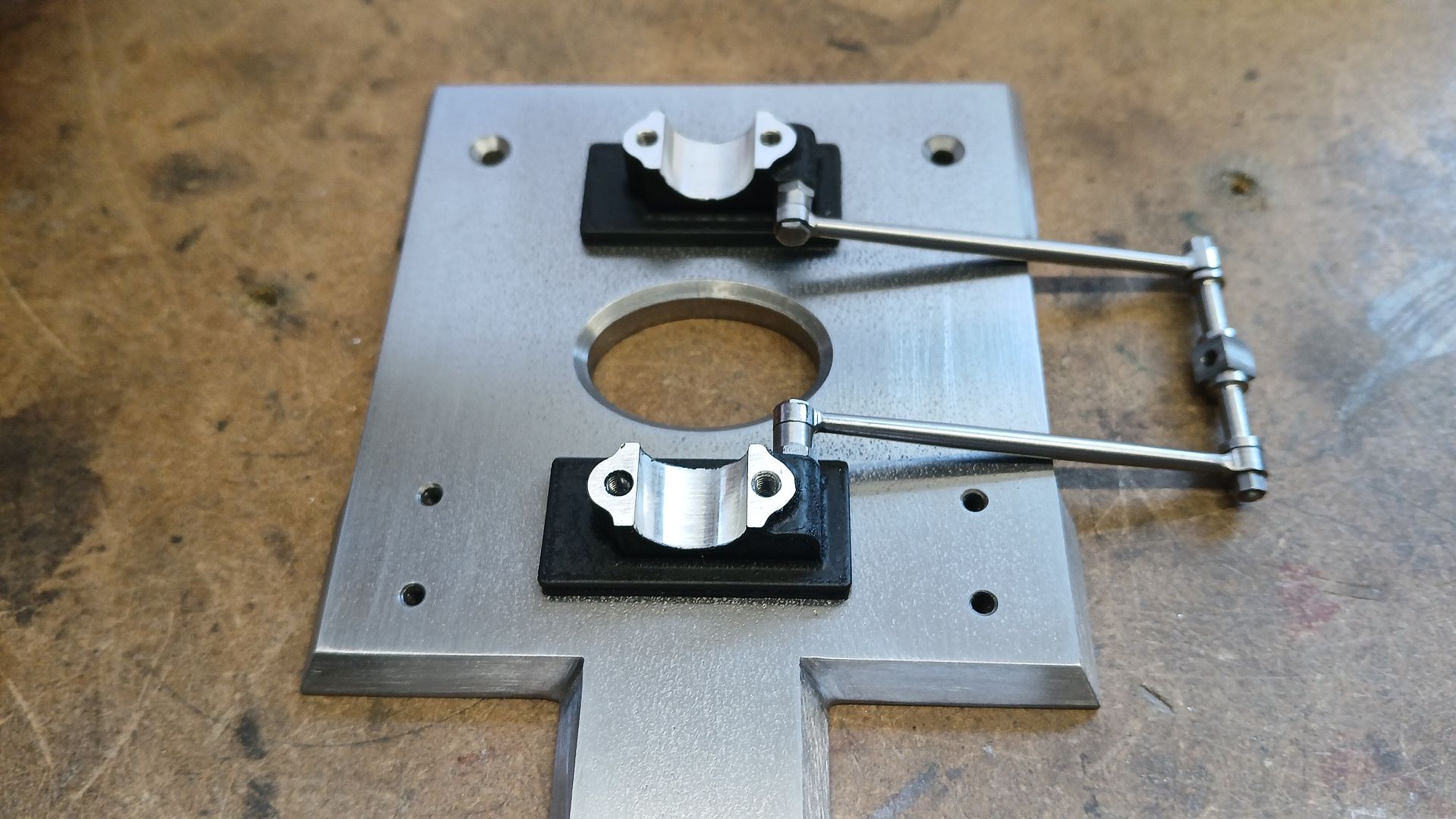
There is not much room to fit the bottom pivots for the valve rods when the cylinder is in position so these were screwed to the sides of the pedestals first. Some 12mm PGMS was held in the pedestals as they were tightened to the base with CSK socket screws from below so the two were in line.
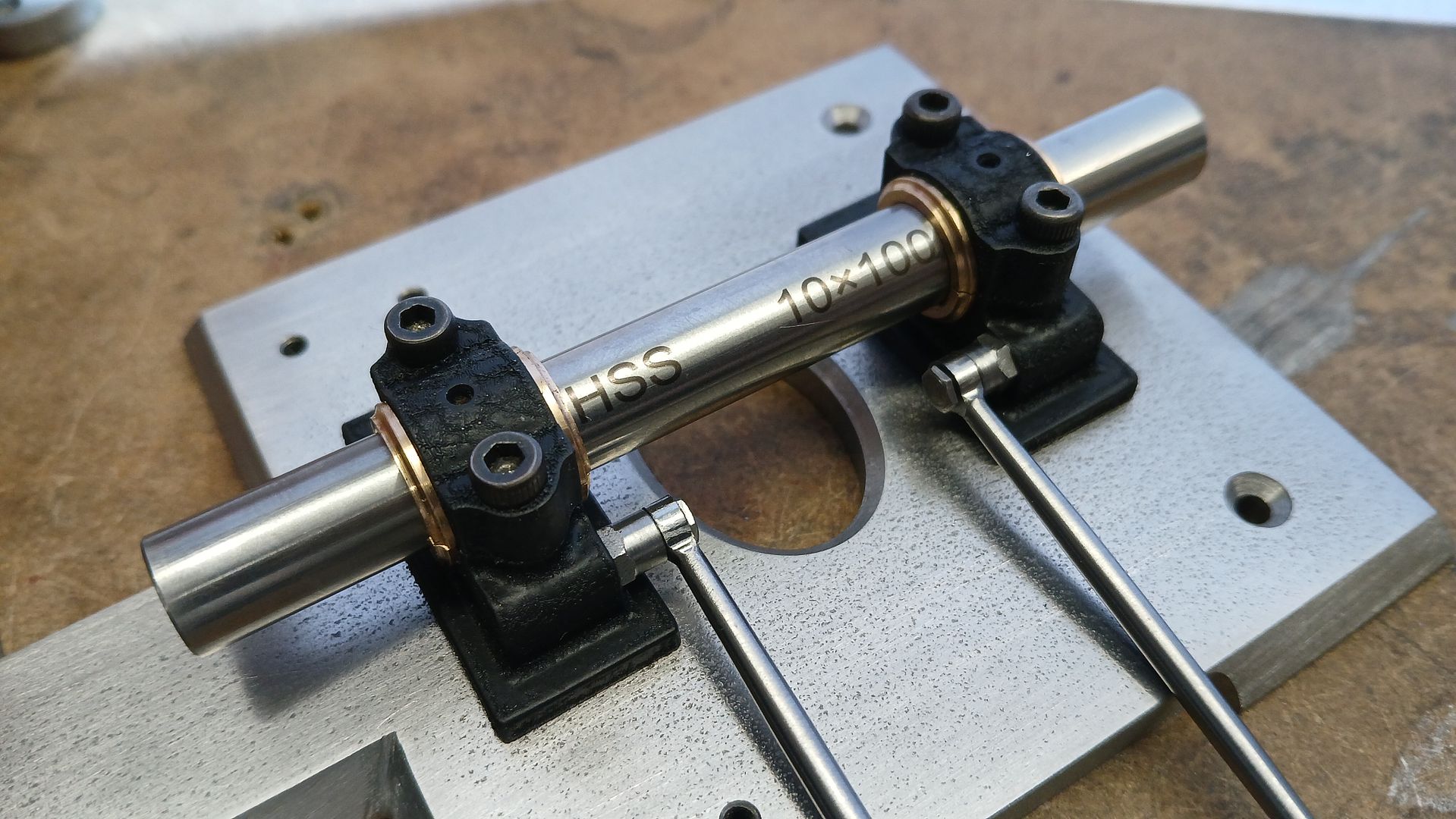
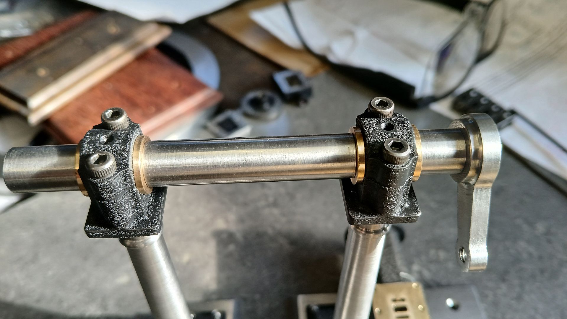
The bearings were then added and a length of 10mm HSS again used to check alignment and fit. I should have allowed a bit more width between the inner bearing flange faces as it took a bit of fiddling to get them to seat nicely due to the thicker than usual paint layer. Cap head screws used at this stage made it easy to take things apart and refit a few times before finally fitting the studs and nuts
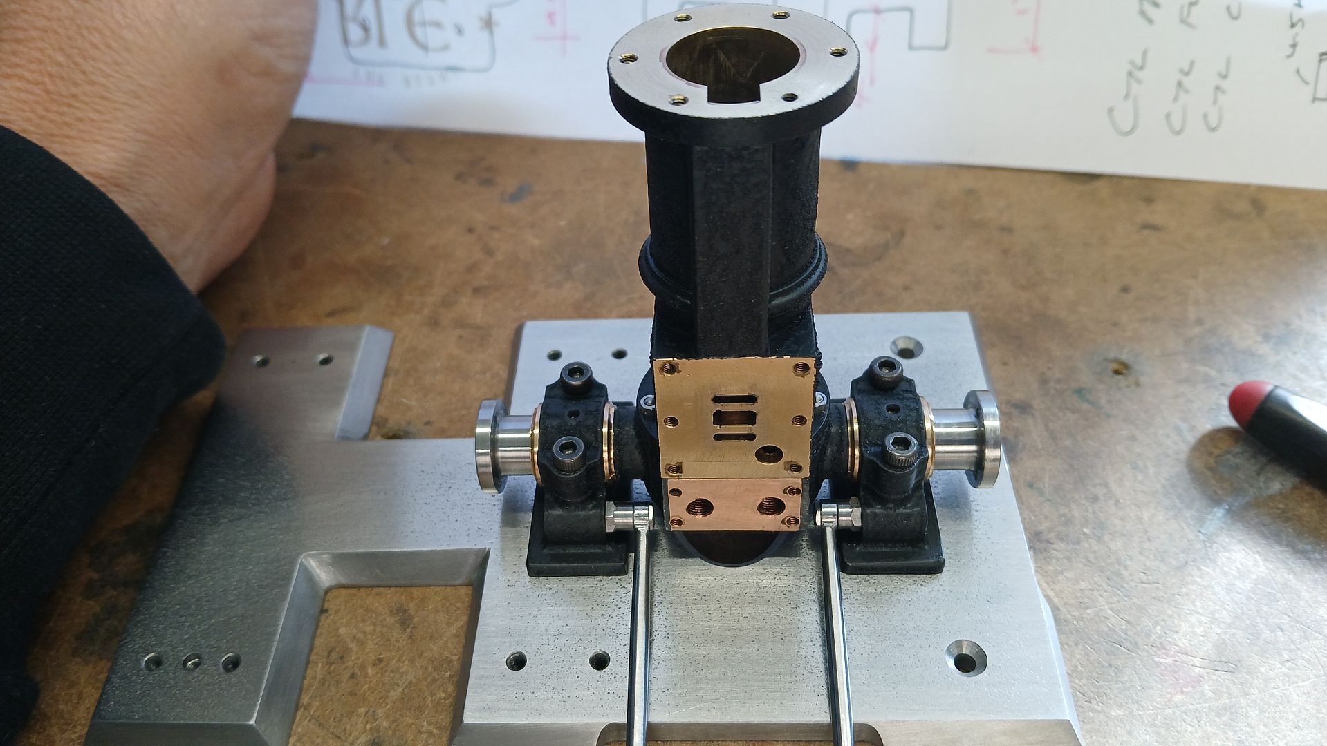
With the bearings all sorted the cylinder was fitted to the trunion and the two then positioned in the bearings and the fit checked to make sure they flopped about freely but without play.
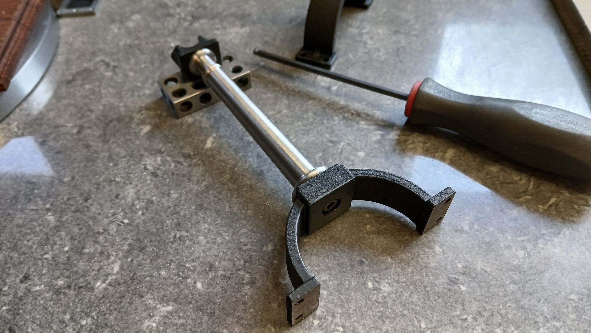
The columns were screwed into the crank bearing housings and then the arched bottoms screwed to the column base with a cap head screw hidden by the counterbored hole. The edge of the housing and the edge of the feet were held on parallel surfaces as the screws were tightened to make sure the crankshaft was at right angles to the feet.
The feet were then screwed to the base and the housings and then the bearings lined up in a similar way to the trunion. You can see why the right order of assembly is needed as you can’t easily get at anything under the column base nearest the cylinder.
Testing the crankshaft fit.
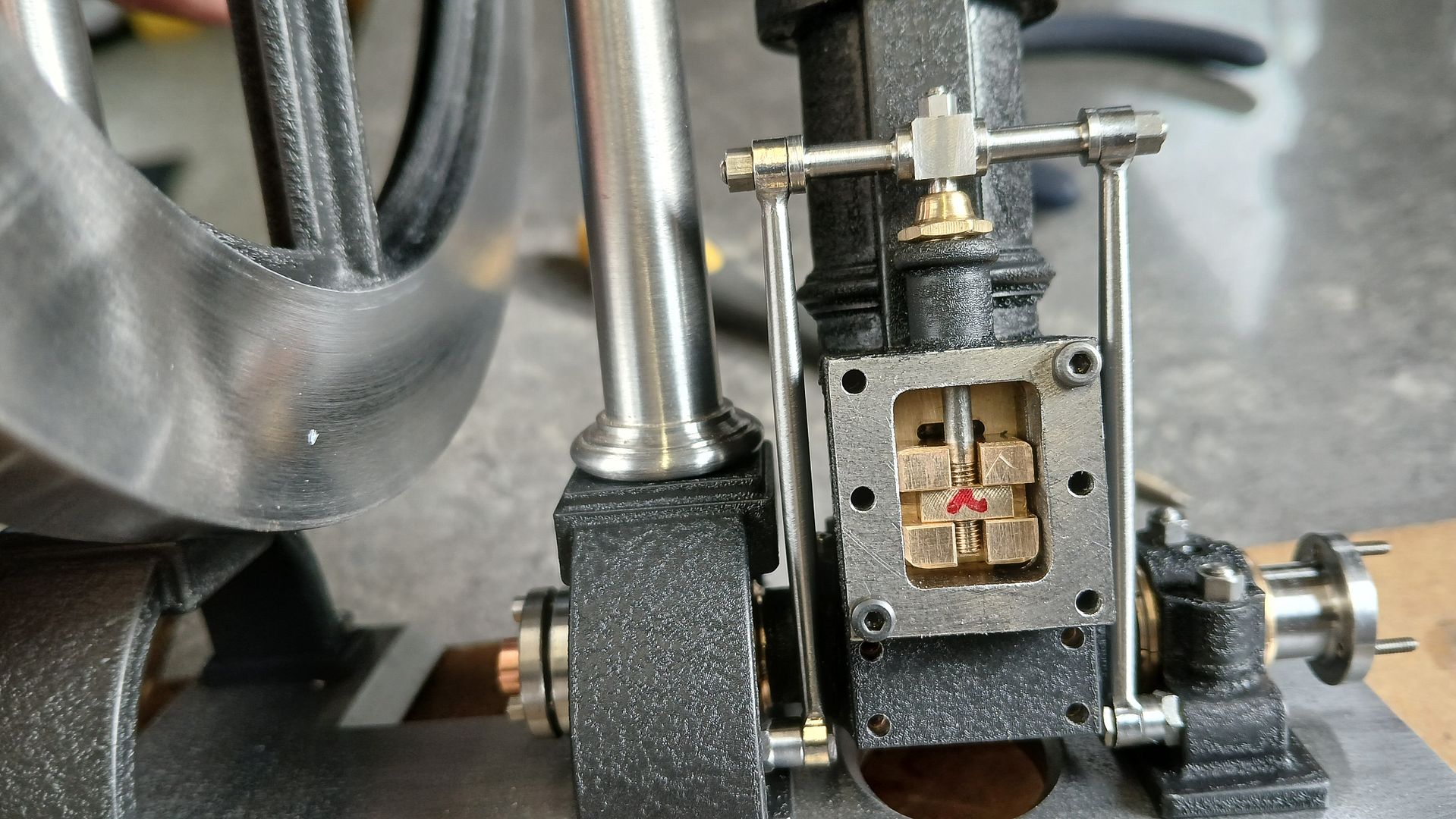
With the piston, rod and big end fitted the position of the valve could be checked to make sure there was equal opening above and below, there is no eccentric to time the valve events, just the geometry of the pivots and linkages relative to the cylinder’s position as it moves from one side to the other.
Thank you for your posting of this build. Especially the valve box photos. Where could i find drawings of such models? Your model and some of the models on the Bonhams auction site are very interesting for a new project.
Excellent engine! First class work resulting in exactly the sort of video I enjoy with breakfast coffee.
A question if I may. I noticed the steam input, ringed in red below, seems to rock with the cylinder, and if so, would twist the pipe:
Never thought of it before, but connecting high-pressure steam to an oscillating cylinder must have been difficult on a full-size engine. Hard to make a flexible steam pipe back in the day I feel. And just as hard to make a leak-proof steam connector to link a moving input pipe to a fixed steam supply pipe. Any idea how they did it?
Thanks for the comments, Wade I will come back to your question later.
Dave, As Duncan says a stuffing box is the answer. In much the same way that they allow piston and valve rods to slide up and down they also allow one part to rotate around another. I real life the pipework would be fixed, often with a bend just after it comes in/out of the trunion as can be seen on say the mcOnie but as I’m only using a short stub for looks then the small amount of friction from the gland packing is making the copper pipe move with the engine.
Wade when you say “such models” do you mean drawings for more detailed and unusual engines rather than the usual stuart offerings or do you mean drawings for barstock made ones that don’t look like they are made from barstock. It will need a different answer for either.
Thanks for the reply, lovely work you have posted. The details on how you built up the supports that I would imagine were cast is inspiring.
Its the unusual engines, not the stuart engines.. for example your Jekyll’s engine and the ones on the Bonhams auction link. I can go a long ways with just a few better photos (as you have now posted) but some rough drawings would not hurt.
There are not so many published designs around for Table engines, you often have to just go by a photo or old engraving and then work it out for yourself. It is not so bad if broken down into each part and you can use the mechanics from known working models and adjust to suit. For example the valve and posrt sizes could be base on a Stuart or other engine as they are hidden away inside the steam chest. Even the Stuarts can be enhanced by adding your own details. This is basically a James Coombes that I only used their cylinder for and made the rest from scratch at a fraction of the cost too.
There are a few drawings available, Anthony Mount has a couple of table engines and drawings can be found in old ME of EiM as well as bought with or without castings from Polly Engineering. Their new web site done not have the full descriptions at the moment but there are quite a nice looking engine. Let me know if you want more details of any of them and I’ll post it here.
Further a field Steam of Steel sell separate drawings or complete with castings though not that cheap.
If you have the ability to open .STP files or use an upto date version of Alibre then I could send my 3D model. Unfortunately I usually don’t produce any 2D drawings for the engines I’m working from, I just take what I need from the 3D model. Also things like those column supports or the cylinder are drawn “as finished” not the individual parts as I know in my head how I will make them so more drawings would be needed if someone else wanted to make the engine.
Looking at the parts modeled it does not look a lot (some small parts not detailed) but the real work is in the fabrications, the cylinder for example is made up of 6 parts, each bridge 6 parts and the flywheel 9 parts.
Jason
That is a lovely model, I like the black crackle finish as well.
I have just had a look at the original on the Bonhams website, I am staggered to see that it sold for £10000.
Phil P
To add another supplier who sells plans (and castings, both grouped and singly) of more perhaps exotic prototypes to Jason’s list above, you might look at AtelierMB in Switzerland.
That’s a good start. I can open most any 3D format, thanks for the offer. That engine you posted is right along the lines of what i am interested in building.. very nice.