I first became aware of this engine about six years ago when it appeared along with some others in a Bonham’s Auction and filled the image and description away in my “Future Projects” folder on the PC. It seems quite a few others like it as the image crops up quite often on sites like Pinterest but I have not seen anyone else have a go at making one.
The original was a fairly large model and I settled on a scale of about 4/10ths based on using a piece of 203mm thick wall tube to make the flywheel rim from which gave me a bore of 16mm and stroke of 48mm. Armed with these numbers I set to and drew it out in Alibre. It took a while to arrive at the right pivot point and length of the valve links to get the slide valve to move correctly on the 3D simulation hopefully it will do the same on the physical model. There are a few areas that I have done a bit differently such as the valve chest but the finished model should be reasonably close to Jekyll’s original.
I have not taken photos of all the work but will show the main fabrications and more interesting bits.
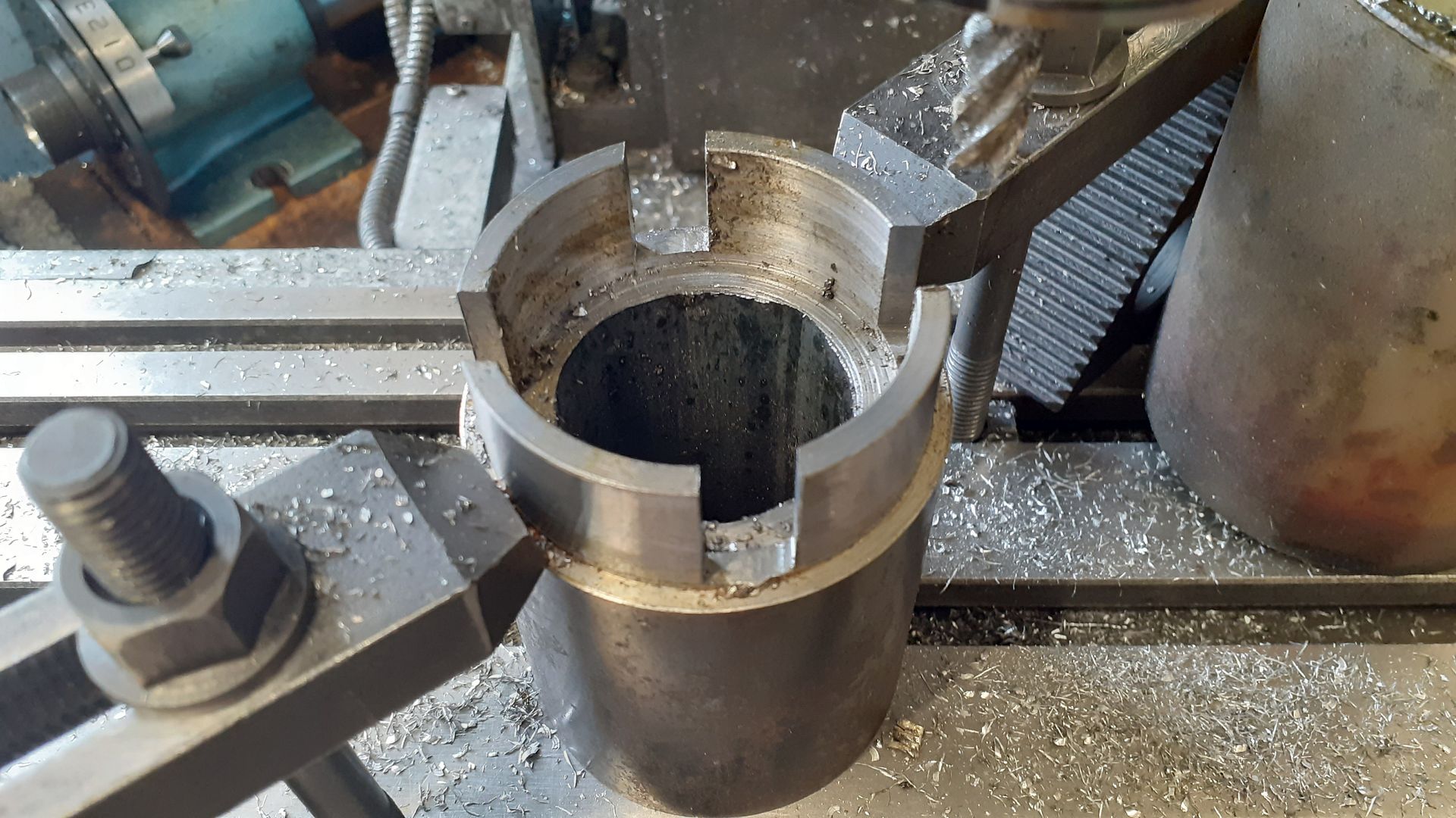
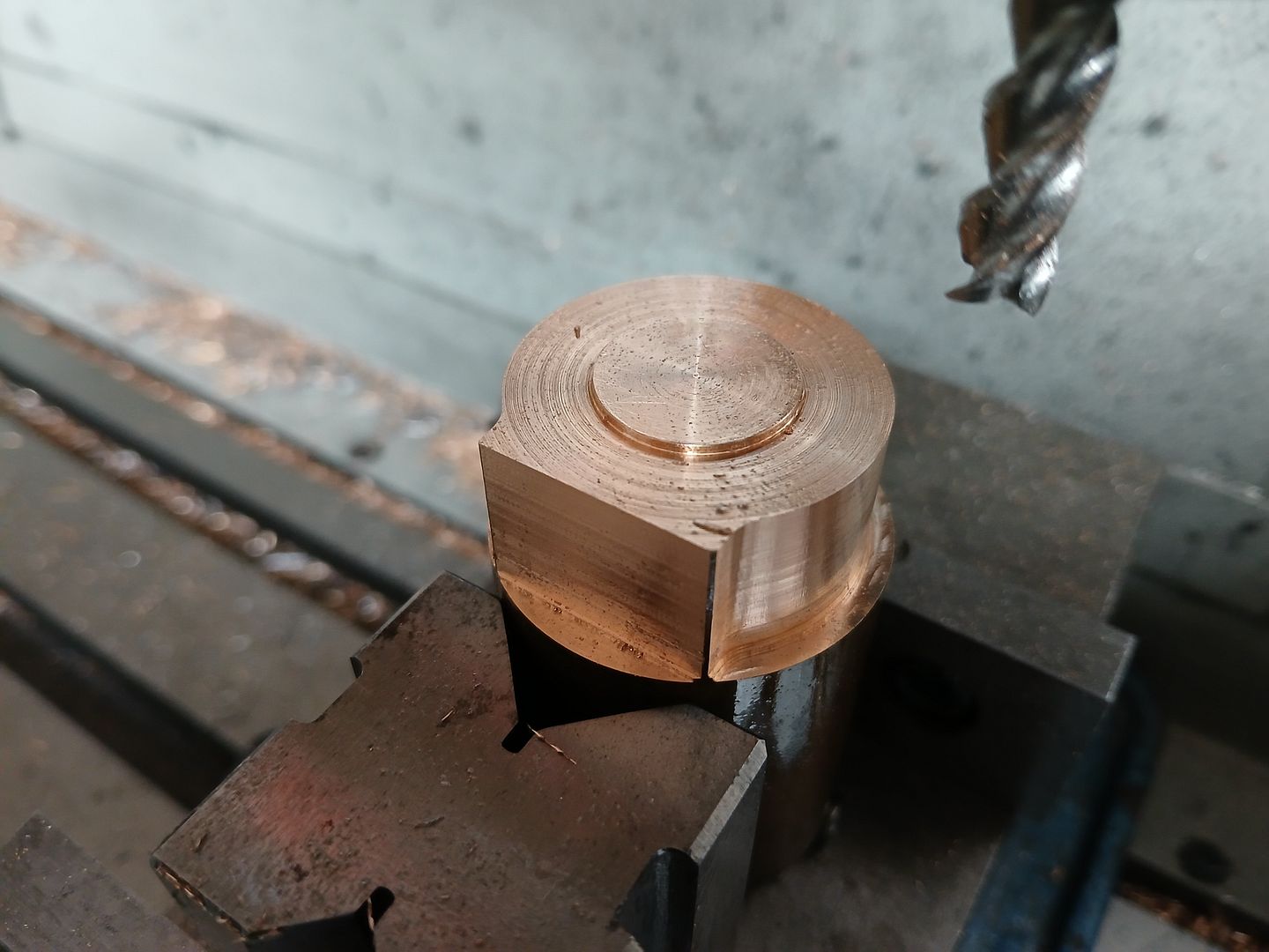
I decided to make a start on the two arched column supports. The actual arch part was made by turning down some more thick walled steel tube to the correct inner and outer diameters and then milling away what was not needed before parting the 4 pieces off.
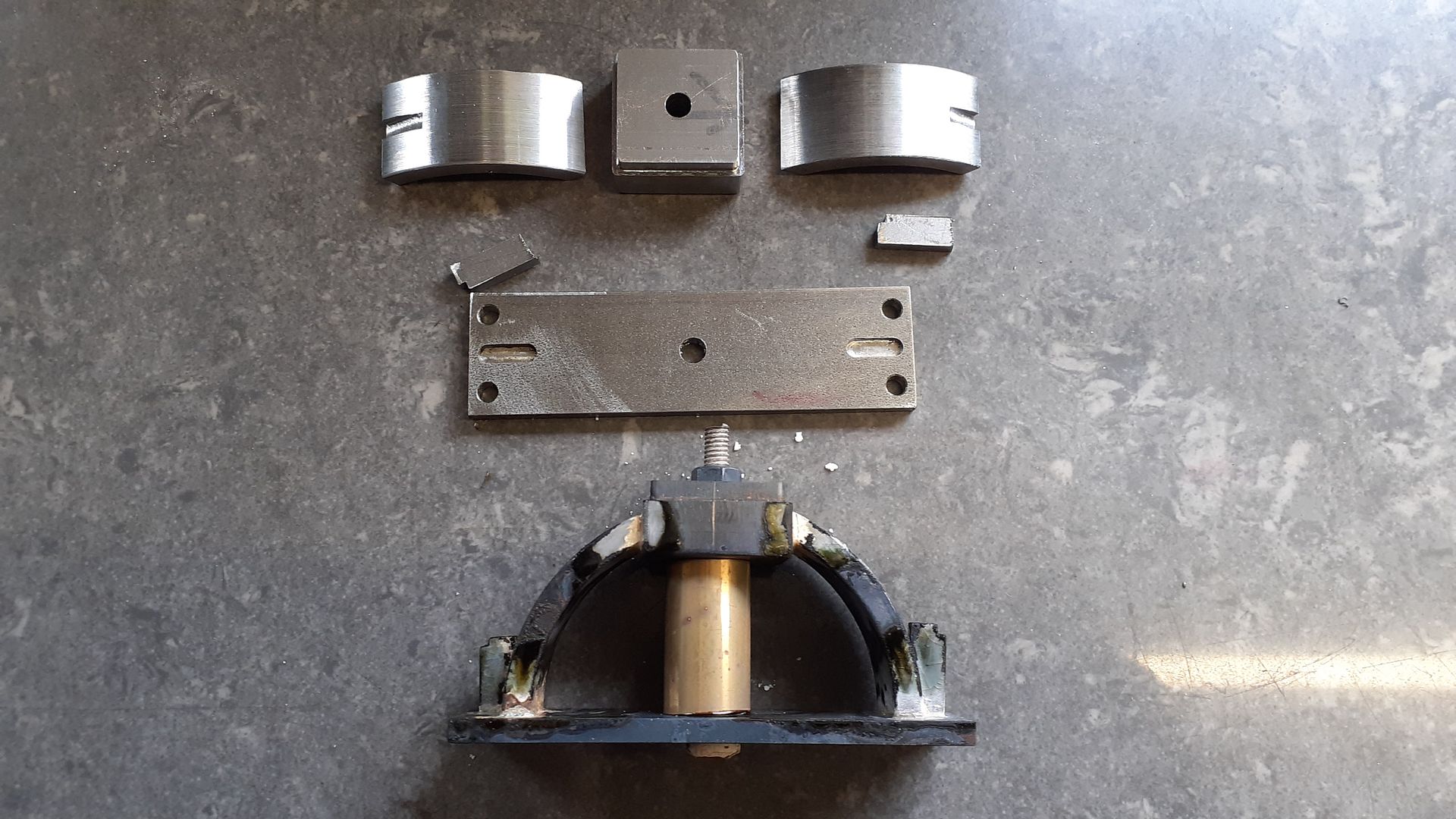
The remaining parts were cut from flat and square bar, I left the feet as one long piece of bar which allowed a bolt to go through the middle with a suitable spacer to hold the square part central and at the correct height for silver soldering.
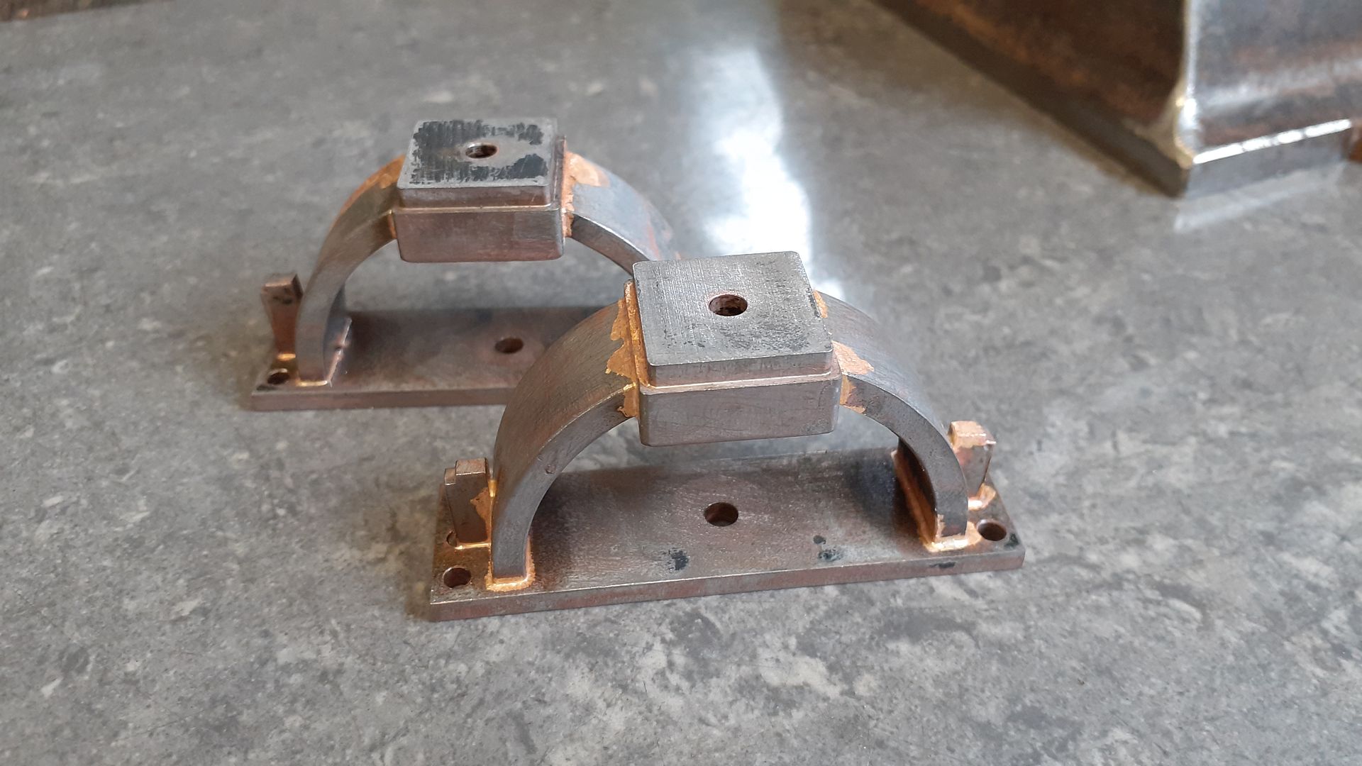
The two “castings” after a dip in the pickle
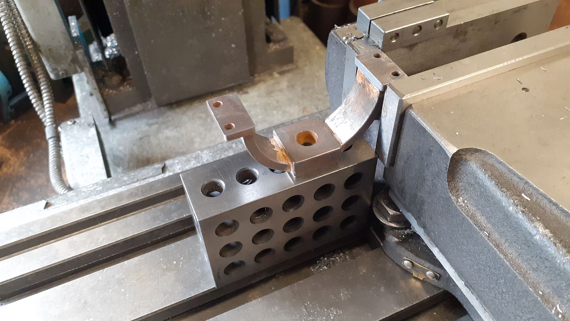
The waste material was then sawn out and the cuts edges milled to final size. The counterbored hole will take a cap head screw to attach the column. The tops will be skimmed to final height once the base plate is made and they can be screwed to it in exact position.
Although the description says “A small full size” I’m not convinced it was ever really intended to do work. There is no pulley to drive anything though that could have been lost over time. The bigger give away is that the decorative wooden base has no sign of any holes that would have allowed the engine to be fixed down so any load from a pully would just pull it over long before any twisting could take place.
There were a few other engines in the auction including this one also by Jekyll, a similar size but I don’t think it was intended to do real work. Interesting way the valve chest and passages are a separate casting.
There were some other engines in the same auction which were from one person’s collection, all would be nice subjects for a model
Not seen the dovetail guides down the side of the cylinder used on anythng else
Michael, I’m not sure why those first two images were not coming up, I just pasted the photobucket URL the same as for the others but tried it several times and the post just displayed the URL. I just dragged and dropped them from my PC in the end.
With all these posts about pendulums I thought I had better get in on the act although with the pivot at the bottom it looks more like a metronome than a dangling penuulum when running. Maybe it should be called a “metronomious” engine?
The image of the other Christies oscillator is not showing from your link but I can get this from the link I posted earler to the Bonhams Auction
I suppose it could be taken two ways, either Jekyll is showing (presenting) it as his work or he has made it and is giving (presenting) it to someone. If the latter you would expect to see the name of who it was presented to and possibly a reason why.
Edit just twigged the RE on the name plate so he was retired.
I don’t know how long his millitary service was but if we assume he retired from service then that would suggest he makes them as a hobby and not to do real work unlike some of the other engines in the auction that were small workshop engines by known manufactureres or in the case of the Maudsley ones probably apprentice pieces.
Unless that is a screen shot of his mention that has fallen foul of the forum software and may show up tomorrow you will have to give me a clue to whereabouts on the list he gets a mention. I must have missed him as I looked through it.
Do we assume that is who he presented the engines to as there are several others that say presented by $$$$$$$ though most say deposited by $$$$$$$ not sure of the difference perhaps they wanted them back?
Would have been an interesting place to look around.
I agree it is an Interesting way the valve chest and passages are a separate casting, I notice there is what appears to be a handle on the end of the governor arm? odd? why the extra 2 holes in the parallel motion arms? and there is something interesting happening with the lower valve gear. If anyone could enlighten me I would be grateful.
The handle is actually on the end of the eccentric rod, you see this fairly often on early engines, it allows the valve to be uncoupled which can help if turning the engine over by hand or starting/stopping. Known as a Gab
I can’t see that the governor actually does anything.
Not sure of the two extra holes
Valve gear is fairly straightforward, there is an angled lever there the eccentric rod connects to that is fitted to one end of a horizontal rod, two horizontal levers also on the rod transfer the movement of the eccentric rod to a vertical movement in the rode seither sid eof teh valve chest then a yoke joins the two outer rods to the central valve rod. rods into the. Similar sort of thing to this except eccentric rod is coming from above not below
The image of the other Christies oscillator is not showing from your link but I can get this from the link I posted earler to the Bonhams Auction
I suppose it could be taken two ways, either Jekyll is showing (presenting) it as his work or he has made it and is giving (presenting) it to someone. If the latter you would expect to see the name of who it was presented to and possibly a reason why.
Edit just twigged the RE on the name plate so he was retired.
I don’t know how long his millitary service was but if we assume he retired from service then that would suggest he makes them as a hobby and not to do real work unlike some of the other engines in the auction that were small workshop engines by known manufactureres or in the case of the Maudsley ones probably apprentice pieces.
RE is ‘Royal Engineer’, not retired. Michaels research identified Jekyll’s famous daughter Gertude, born 1843, dating her dad a little later than 1800. At that time the Royal Engineers were the UK’s main source of trained professional engineers – the Army paid for their university equivalent training. Before the Industrial Revolution, and well into the early Victorian period, almost all large engineering projects were military. Fortifications, dockyards, road systems, canals, dams, irrigation systems, bridges, surveys and maps, balloons, etc. The Royal Engineers were deep into all things technical, and high-end, not labourers! Many early Railway Inspectors were ex RE, including the first.
Joining the dots, I think Captain E Jekyll RE was a number-crunching professional engineer, supervising others. Michael’s link supports the ‘man in charge’ view, my bold: ‘The following very Superior Collection of Models were constructed under the immediate direction of E. Jekyll, Esq., late Captain Grenadier Guards‘. As the models are of fortifications, I suggest he had them made to inform new officer students, ended his career as an Army educationalist. Very likely he was a talented machinist in his own right, at work and in his spare time, before and after retirement. The engine could be a private endeavour, or ordered for educational purposes.
He’s not in Graces Guide. Anyone got an account with a geneology research website? Might be possible to find more via his daughter and the families death, births, census and army records etc.
I see the model sold for £10,000! Wonder how much my PottyMill is worth? Perhaps if I paint it!
Not necessarily – and in this case, it would have been a bit of a career leap from the Grenadier Guards to the Royal Engineers, surely?
RE are the post-nominal letters indicating a Fellow of the Royal Society of Painter-Printmakers (formerly the Royal Society of Painter-Etchers and Engravers).
Don’t know if any lists of such Fellows are available? Might provide a bit more enlightenment.
Of course, I could be totally wrong – I initially thought Jason meant he was retired from the Army due to the “Late Grenadier Guards” phrase rather than the RE.
Rob
Edit – feel free to ignore all the above, the Society was not formed until 1880, so that blows that theory out of the water, doesn’t it?
Michael, I’m not sure why those first two images were not coming up, I just pasted the photobucket URL the same as for the others but tried it several times and the post just displayed the URL. I just dragged and dropped them from my PC in the end.
…
Been too unwell to make any progress into what causes erratic image processing, but webp may be involved. webp is a compression system invented by google in 2010 that’s gradually replacing alternatives like jpg or png. It’s designed to compress web images, and in that mode can get the image down to as much as 20% of the equivalent jpg.
Misleadingly, it seems the URL to a webp can be suffixed “jpg”, but it isn’t. Browsers cope, but the forum doesn’t understand webp, and fails silently.
I’ve also had failures with jpg and png files produced by an image converter. I often convert eps diagrams and pdf text/images into jpg or png: once in a blue moon the forum gags on one, reason unknown.
It’s possible Photobucket processes images too. I’ll do some digging.
If it is down to photobucket I would have thought all the images would be affected not just the first two.
Thanks for all the interest. I must admit apart from the fact he had a famous daughter which was mentioned in the Bonhams listing where I first saw the engine I had not given the builder much more thought, it was just that I liked the engine.
Back to the build as I’ve had people asking me about that.
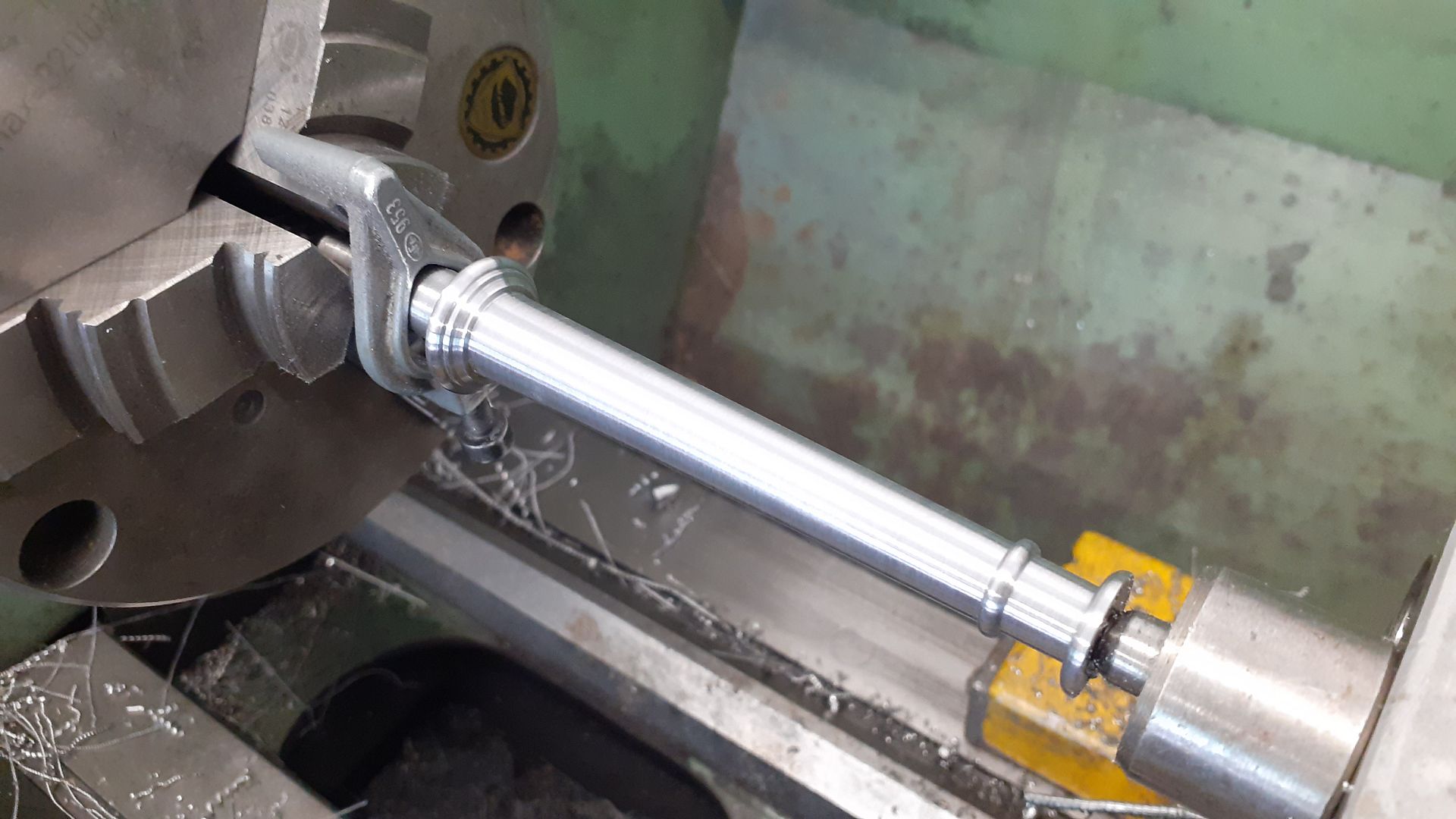
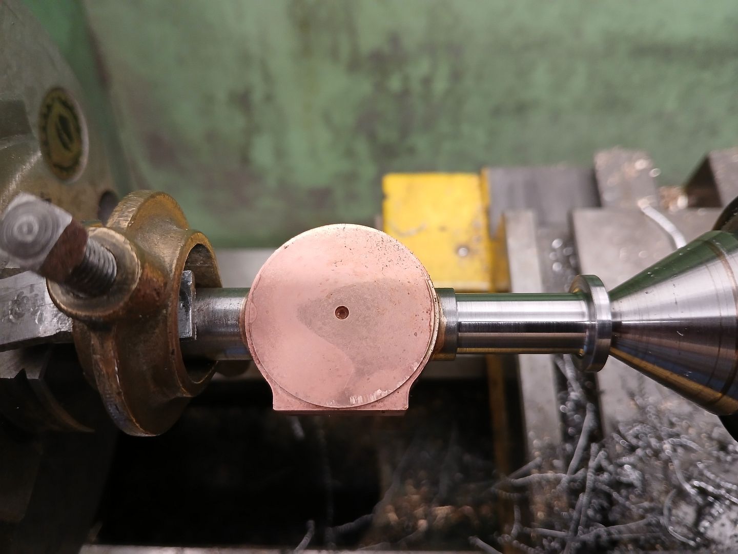
The columns were fairly straight forward, after facing both ends were deeply ctr drilled and then tapped – the deep drilling meant there was still some of the conical hole around the tapped area. After roughing out between ctrs, the decorative mouldings were done with a combination of small parting tool, form tools and some filing of the revolving work. Lastly a small revolving ctr was held in a tailstock mounted boring head and set over to obtain the taper.
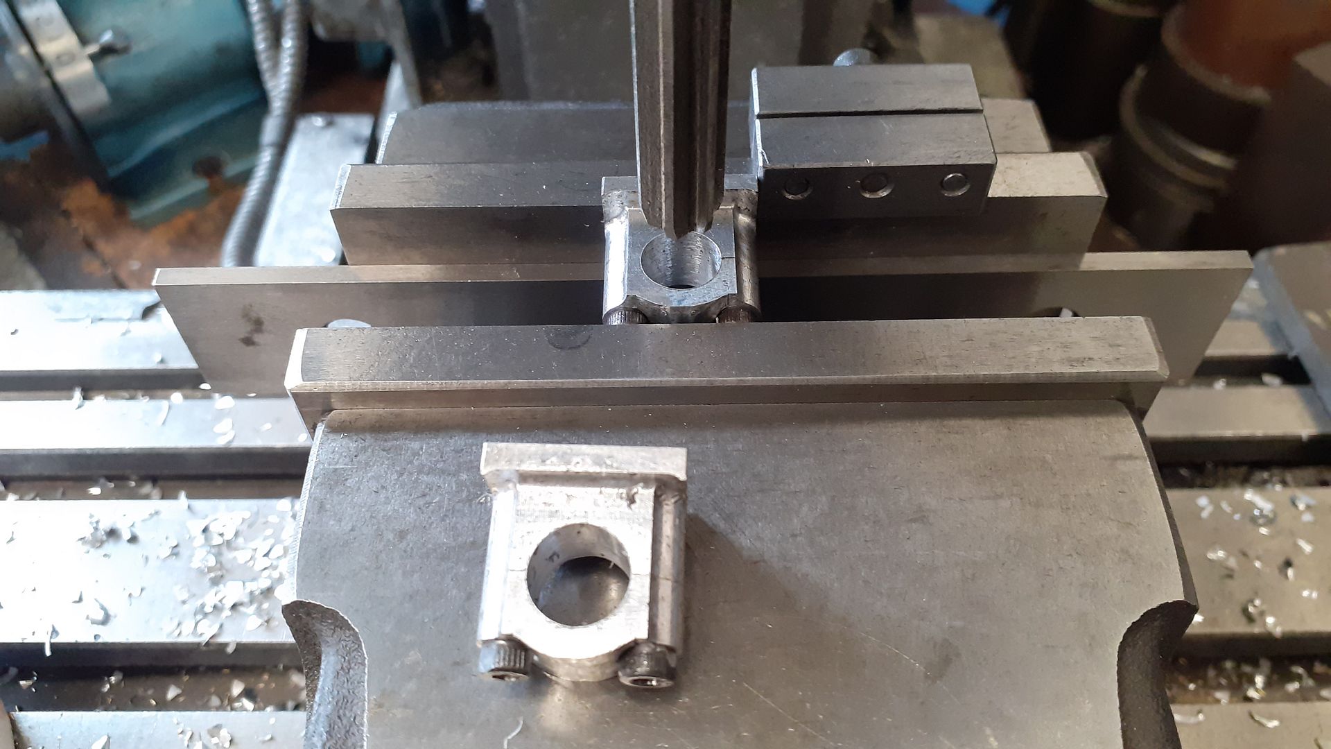
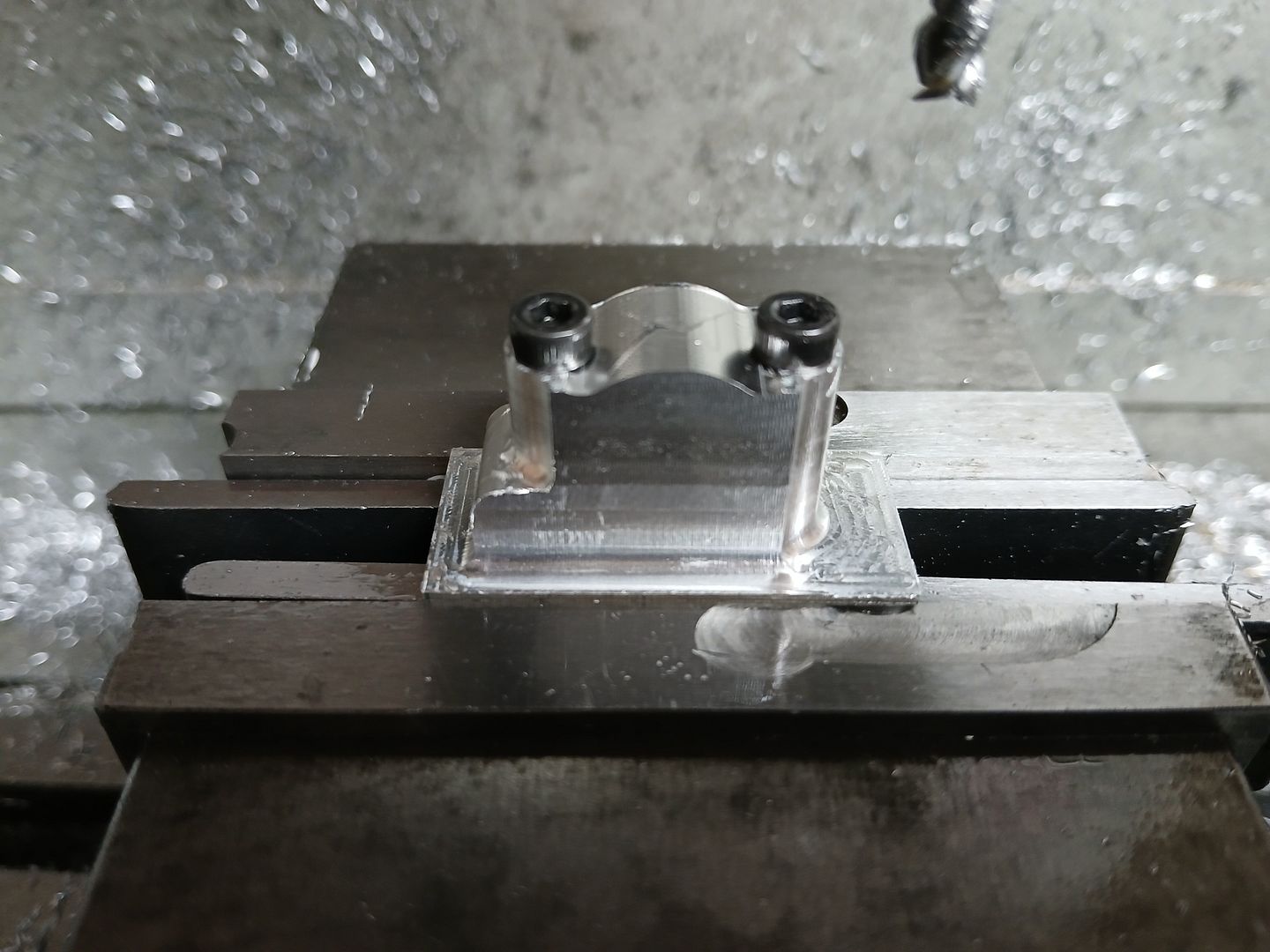
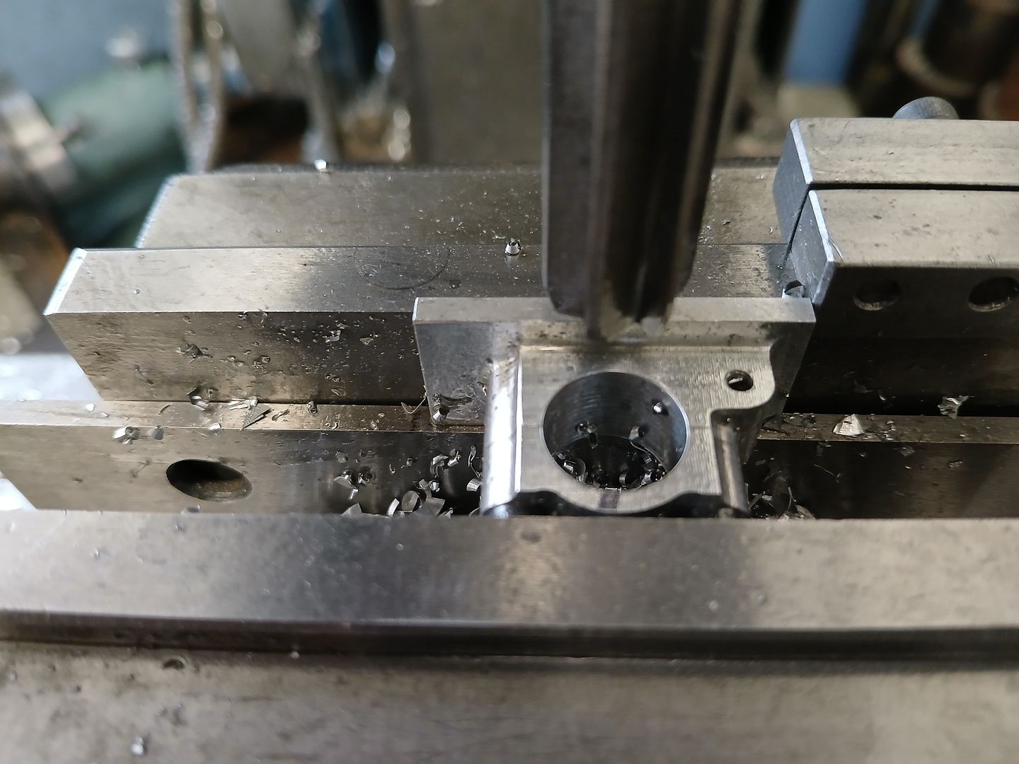
both the crankshaft and trunion bearing housings started off as suitably sized rectangular blocks for their tops and bottoms which were drilled and tapped for the studs on the manual mill. Then over to the CNC (could be done on a rotary table) to first cut the hump backed top of the caps. The caps could then be screwed onto the lower halves and the vertical faces cut to contour. With them still screwed together they were set up on the manual mill to be drilled and reamed ready for the bronze bearings and in the case of the trunion ones holes were also tapped in the sides for the valve rod links to pivot from.
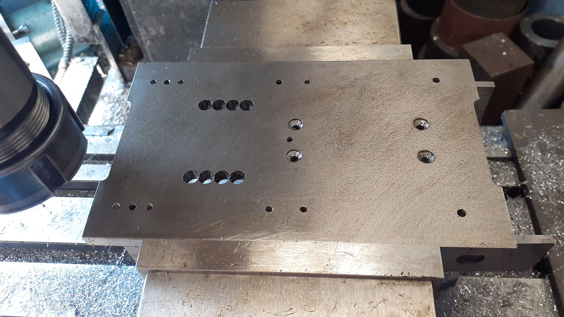
The base plate was cut from a piece of 6 x 100 flat bar and milled to overall size. It was then held upside down to drill the various holes as there were a couple of blind ones for attachment to the wooden base in the bottom face as well as four CSK ones to hold the trunion bearings. I also ran a row of stitch drilled holes where the bottom of the two cut outs were.
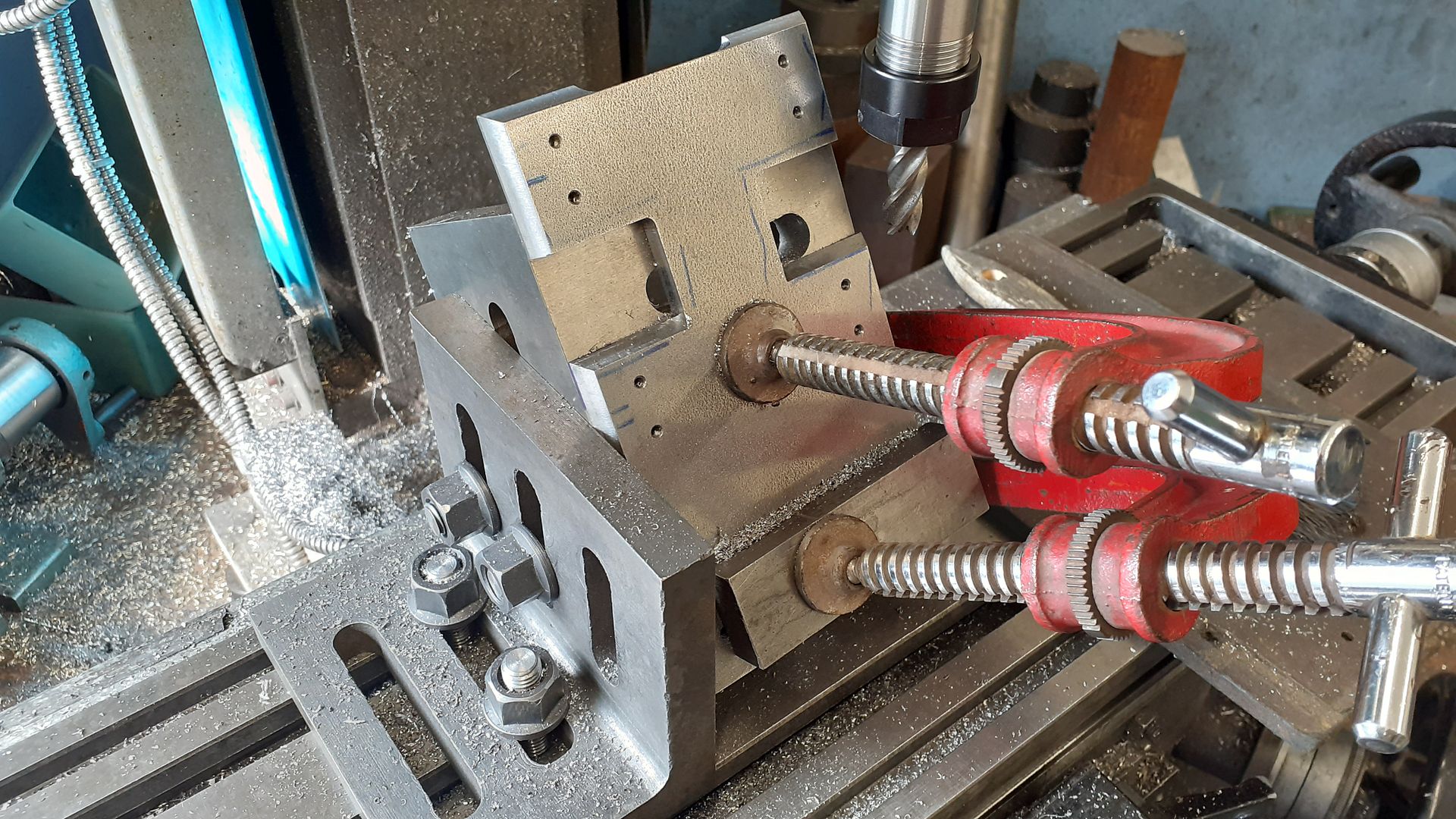
I then set up a pair of angle plates to give the correct angle for the chamfers clamping the plate to that to mill each side. I had to change from ER32 to ER 16 to get at the inner chamfers to avoid rubbing my nuts. I cut as close as possible to the internal corners and then finished them off with some file work.
Not necessarily – and in this case, it would have been a bit of a career leap from the Grenadier Guards to the Royal Engineers, surely?
…
Of course, I could be totally wrong – I initially thought Jason meant he was retired from the Army due to the “Late Grenadier Guards” phrase rather than the RE.
Rob
Decoding this stuff is always a guessing game. I’m about 90% sure RE is Royal Engineer. Although the Royal Engineers were a Corps, their role was to support the Army, and individuals would be seconded to other units. Being both RE and Grenadier Guards was something to be proud of – both elites.
According to Google, the correct abbreviation for ‘retired’ applied to military rank is ‘Retd’, but this might be USA only, and might not have been the case when these models were built/presented
We need to remember that Henry Jekyll morphed into Edward Hyde, so perhaps our mystery military man had a split personality
If it is down to photobucket I would have thought all the images would be affected not just the first two.
I looked into Photobucket and one of their main selling points compared with competitors is they do not compress photos or videos stored on their platform. So not guilty!
Thanks for all the interest. I must admit apart from the fact he had a famous daughter which was mentioned in the Bonhams listing where I first saw the engine I had not given the builder much more thought, it was just that I liked the engine.
…
I like it too, and your recreation.
Bit more info, Edward Jekyll was born 1804, died 1876. His son Col.Sir Herbert Jekyll b1846 d1932 was also a Royal Engineer.
The trunion is probably the most critical part to get right on the engine as you need it to rotate truely so that the big end stays at the same distance from the crank as the piston goes in and out. I started but milling the profile on the CNC leaving 0.5mm on the port face so that could be finish machined after soldering.
After sawing off from the bar the other side was faced but again left oversize, I then bored two holes in from the sides and silver soldered in some partially turned steel that would form the pivots. There were oversize externally but finished internally for the steam passages and glands. After soldering and a dip in the pickle the trunion was mouted between centres and the diameters turned down to a running fit in the 10mm dia bearings, doing it between ctrs ensured the two turned diameters were inline and concentric.
I then set the fabrication onto two Vee blocks on the rotary table so that the face and spigot that locate with the bottom of the cylinder could be finished true to the pivots. Lastly stud and passage holes were drilled.
The bearing blocks for the trunion are quite similar to those for the crankshaft with the exception of a boss that gets tapped to allow an anchor point for the valve links to screw into.
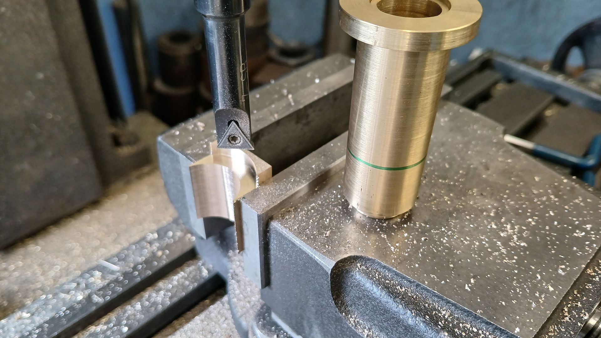
The cylinder is quite similar to several others I have made consisting of a roughed out “tube” with spigots on either end, two “washers” to form the end flanges and a couple of blocks with concave surfaces that are all soldered together with a decorative bead for good measure. The blocks that form the valve face and steam passage have slots cut into the concave surface which act as the steam passages. Here the valve block is having the concave surfaces machined for cylinder and flange with a boring head. Just missed the chuck jaws!
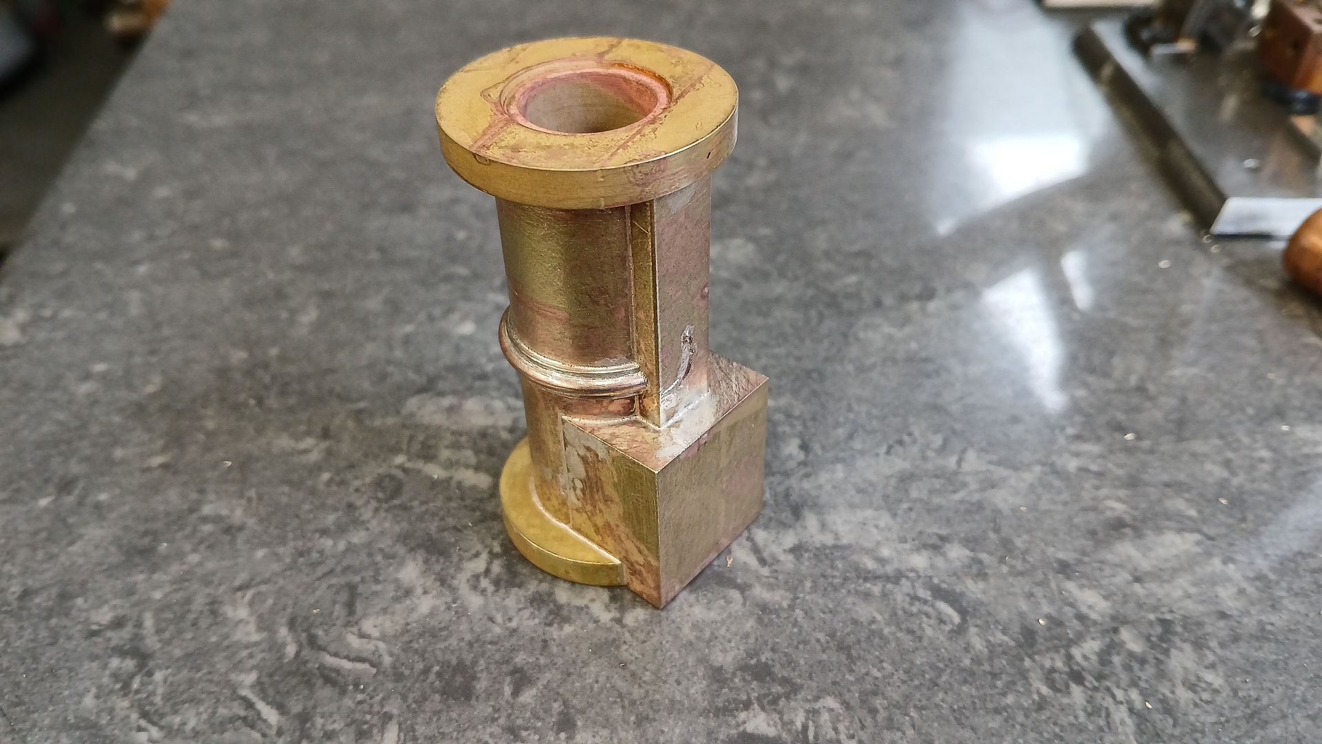
The completed fabricated cylinder “casting”
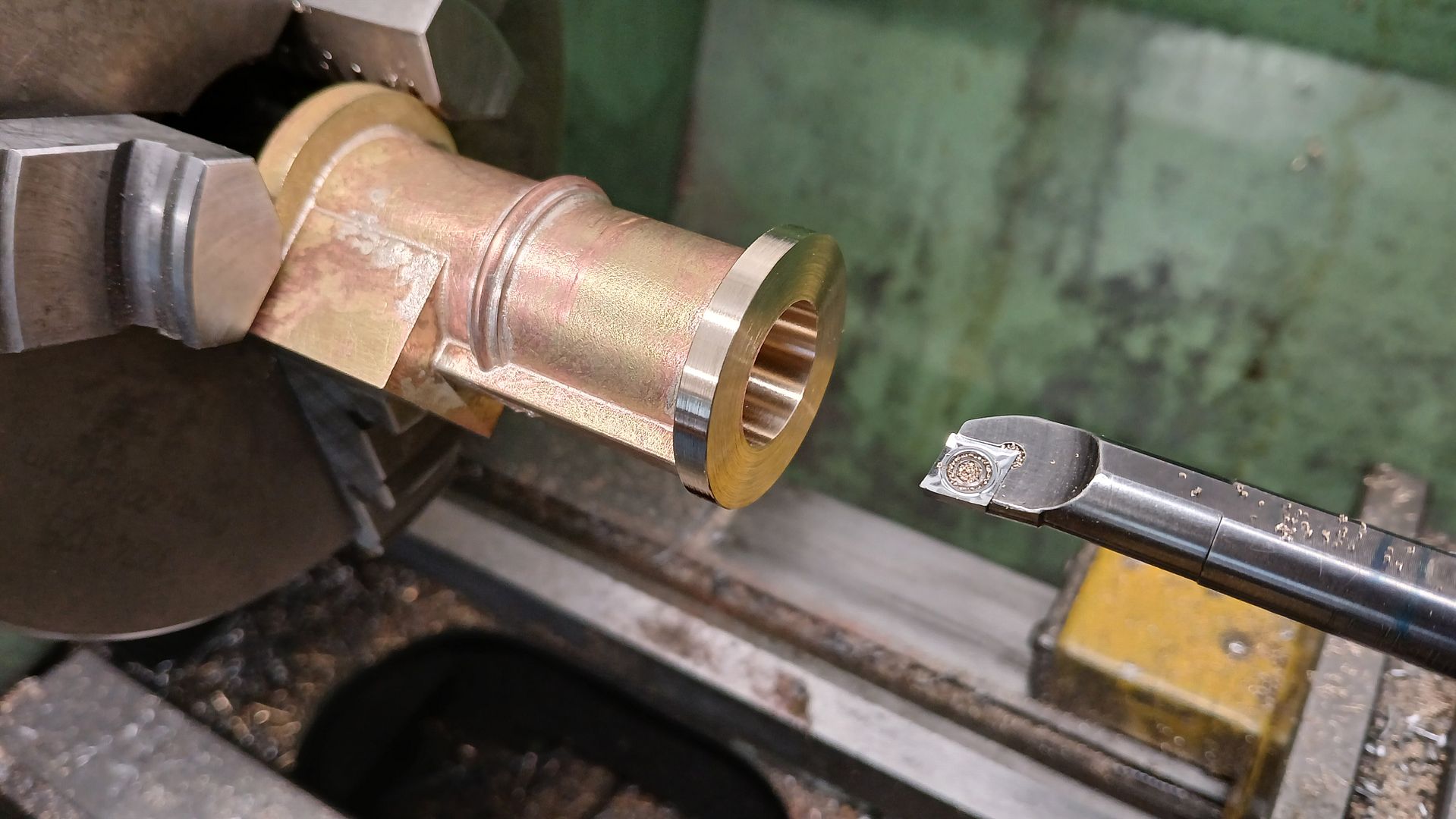
This can now be machined much like you would a casting by boring, facing the end and cleaning up the OD of the flange, then turn around and do the face and OD of the other flange.
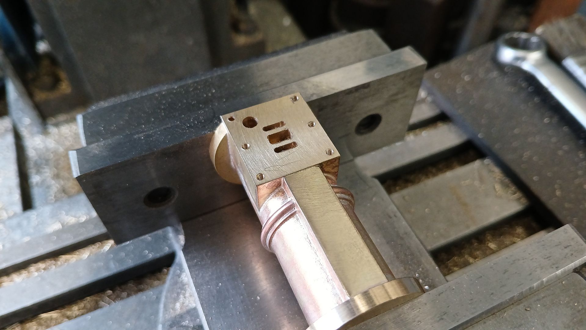
The port face can then be milled flat, ports cut and the various holes added. The large one towards the bottom is the steam inlet which intersects with a similar diameter hole drilled up from the bottom. That hole corresponds with one in the top face of the trunion that is then connected to the hole that comes in through the trunion bearing. Similar setup for the exhaust.
It is quite a tight space to get everything in, the ports are 1.5 x 6 for inlet and 3×6 for exhaust, studs M2 and the steam passage 3.5mm.