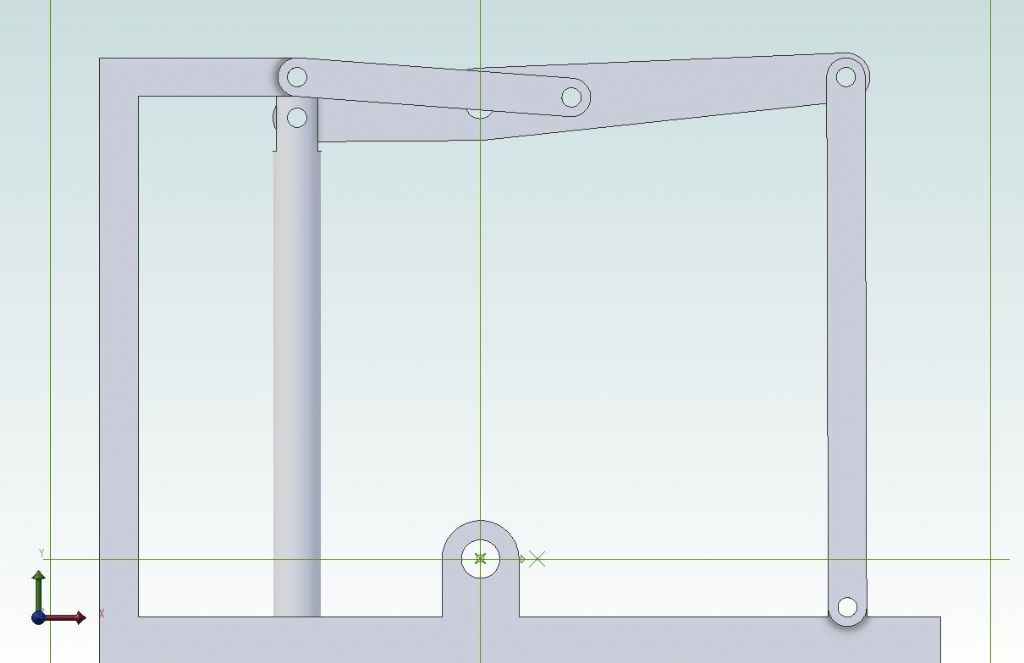
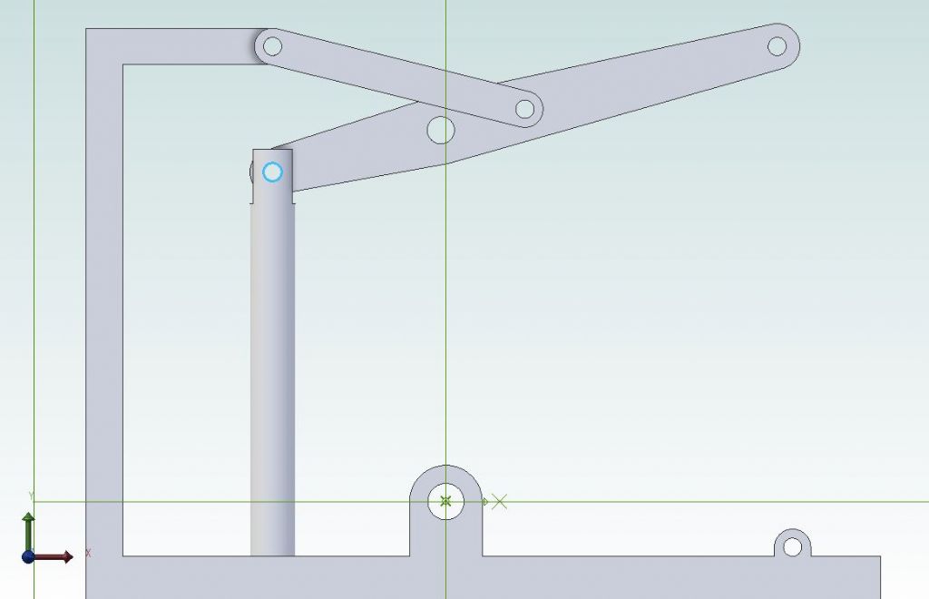
JDW Grasshopper engine
JDW Grasshopper engine
- This topic has 27 replies, 7 voices, and was last updated 12 November 2022 at 15:08 by
 JasonB.
- Please log in to reply to this topic. Registering is free and easy using the links on the menu at the top of this page.
Latest Replies
Viewing 25 topics - 1 through 25 (of 25 total)
-
- Topic
- Voices
- Last Post
Viewing 25 topics - 1 through 25 (of 25 total)
Latest Issue
Newsletter Sign-up
Latest Replies
- Speed camera
- Amadeal AMABL210E Review – Any Requests?
- The Perpetual Demise of the Model engineer
- Colchester Chipmaster Clutch question
- Advice moving 3x machines
- Firth Valve Gear
- What Did You Do Today 2025
- A Persistent Scam
- ML10 backgear
- Boxford lathe & vertical mill VFD conversion help with start stop


