Jason’s Firefly .46 Build

Advert

Jason’s Firefly .46 Build

Home Forums Work In Progress and completed items Jason’s Firefly .46 Build

Viewing 25 posts - 126 through 150 (of 170 total)
  • Author
    Posts
  • #382119
    Ian Hewson
    Participant
      @ianhewson99641

      Thanks Peter and Jason

      Solid bearing it is then, always good to have advice, just been checking my taps, gues which one I don’t have for the plug lol.

      Advert
      #382130
      JasonB
      Moderator
        @jasonb

        Make sure you get 1/4×32 UNEF not ME

        #382131
        Ian Hewson
        Participant
          @ianhewson99641

          Thanks Jason, just noticed the two different threads whilst looking for the best supplier.

          #385018
          Peter Wood 5
          Participant
            @peterwood5

            I am now making a second Firefly learning from the mistakes on the first and adding cooling fins to the head and beam mounting.

            On the first one I used a commercial prop driver but this time I want to make my own.

            Two questions.

            How do I drill a hole with a flat. Jasons excellent thread does not mention this part.

            Would I be better making a tapered split collet to secure the driver on the prop shaft?

            Secondly how do I mill the radiused grooves on the driver face?

            Peter

            #385043
            JasonB
            Moderator
              @jasonb

              Peter, this came up the other day in this thread if you follow my link in that thread you will also see one simple way to do the serrated face.

              #385062
              geoff walker 1
              Participant
                @geoffwalker1

                Peter,

                If you don't want to make a stepped broaching tool you could make a keyed driver instead.

                I made one for my firefly. you would of course have to mill a keyway slot in the crankshaft.

                If you go back to page 5 in this thread you will see the driver and crankshaft with the key fitted in my parts photograph.

                Geoff

                #385082
                Peter Wood 5
                Participant
                  @peterwood5

                  Jason

                  Thanks. I missed that thread. The use of a vertical knurling tool is a great idea. I have previously made prop drivers for larger engines for friends by tilting the mill head at 45 deg and just making grooves across the face but I felt this needed proper radial knurling.

                  However not having an arbor press I am not keen on using my mill or Myford in that role.

                  Geoff.

                  Milling the keyway in the crankshaft is not a problem. Thinking about it I have made internal keyways as required on the prop driver by drilling the correct size hole on the joint line of the crankshaft hole and a temporary plug. Then it is just a matter of squaring the hole with careful filing.

                  Meanwhile I am still contemplating a split tapered collet as was made in the RCME build article.

                  Peter

                  #385091
                  Peter Wood 5
                  Participant
                    @peterwood5

                    Jason

                    Just tried the knurling technique with an old rusty tool I had in my scrap box./Worked like a charm. Thanks

                    Peter

                    #385094
                    JasonB
                    Moderator
                      @jasonb

                      Peter, I'm not sure about your arbor press comment, I just did mine in the bench vice with an odd 1/2" drive socket as a spacer

                      #385097
                      Peter Wood 5
                      Participant
                        @peterwood5

                        Aaaaah. Misunderstood the picture. I thought it was vertical not horizontal.

                        After my breakthrough with the old knurling tool i will give your broaching method a try. Thanks again.

                        Peter

                        #389561
                        Ian Hewson
                        Participant
                          @ianhewson99641

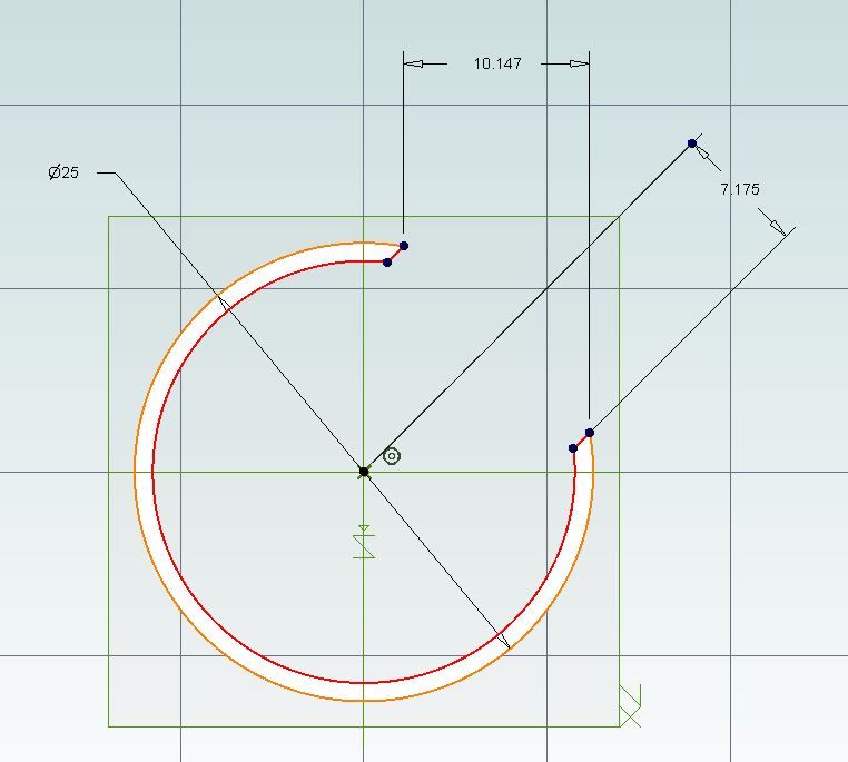
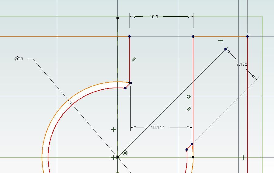
                          A question about the port dimensions, the cylinder block exhaust port is shown as 10.5mm x 5.5mm, whilst the cylinder liner port is shown as 15.285mm x 4.96mm.

                          How critical are these dimension as the are shown to three places of decimals?

                          I would have thought that the liner would have been the important dimension for the exhaust, is it to do with back pressure as in a car engine?

                          As I mentioned before, I have not had any experience with 2 stroke engines.

                          #389563
                          JasonB
                          Moderator
                            @jasonb

                            The three decimal places of the exhaust port are more a product of the CAD package when it rolls the liner out into a flat plane, the 14.35mm is what you will actually machine.

                            Width wise you have a bit more leway but the heights of the ports are what really set the timing of the engine so they are what you should aim to get as close as possible.

                            The crank case hole is a little larger than the port in both directions so it does not offer any resistance to gas flow and is less critical than the liner.

                            #389568
                            Ian Hewson
                            Participant
                              @ianhewson99641

                              Hi Jason

                              Thanks for your prompt reply, appreciated, so the holes on the liner are the critical ones, and should not be restricted in diameter by the holes in the block when it is fitted?

                              The 10.5mm exhaust hole was the one that was confusing me as it seems to restrict the port in the liner.

                              Just measured the plan, and I can now see that the 14.35mm is due to the curvature of the cylinder, didn’t want to bu**er up the block on the last cut.

                              Ian

                              #389588
                              JasonB
                              Moderator
                                @jasonb

                                That's it liner is the one to get right particularly height.

                                The 10.5 and 14.35 are basically one and the same dimension, if you were to project two vertical lines upwards on the drawing that shows the 14.35 the distance apart would be about 10.2 as the 45degree cut is the long edge of a 10.5 x 10.5 triangle with a bit to spare.

                                firefly ports.jpg

                                firefly ports2.jpg

                                Edited By JasonB on 06/01/2019 07:08:57

                                #392794
                                Ian Hewson
                                Participant
                                  @ianhewson99641

                                  Another question, do you use any gaskets or sealants, for the cylinder head, engine backplate or block to cylinder?

                                  #392795
                                  JasonB
                                  Moderator
                                    @jasonb

                                    I didn't but if you feel the need then a smear of a liquid gasket would be the best bet to keep backplate clearance and compression ratio the same.

                                    #392797
                                    Ian Hewson
                                    Participant
                                      @ianhewson99641

                                      Thanks for that Jason, just looking ahead, got the engine built up to the backplate level, going to do the crank and piston next. Lapped the cylinder with diamond paste from Arc, came up nicely.

                                      Interesting build, makes a change from steam models.

                                      Think I have realised what the nipple on the silencer is for, pressurising the fuel tank to feed the carb, no need for the fuel tubes to the mixing chamber in the backplate?

                                      #392801
                                      JasonB
                                      Moderator
                                        @jasonb

                                        The backplate holes are really only for neater plumbing back to the tank as you can run the tubes through the middle of the bulkhead.

                                        So from exhaust to one of the backplate pipes, from that to tank for pressure, from tank clunk to other inner backplate tube and from that to remote needle assembly and finally from there to carb.

                                        #392837
                                        geoff walker 1
                                        Participant
                                          @geoffwalker1

                                          Hi Ian,

                                          Good luck with the rest of your build.

                                          I made two pistons for my firefly. The first one I made a poor job of lapping it into the liner. The engine ran but lacked power and when used on a model aeroplane it just had enough power to "limp" into the air.

                                          With the second piston I made sure it had a good square leading edge and I only lapped it up to TDC. The first piston I lapped right up to the end of the liner which was a I feel the mistake I made.

                                          If you do some calculations you will see that TDC is 0.8 mm below the underside of the cylinder head boss. I lapped up to that point and it made a big difference to the compression and the power output.

                                          Just my thoughts Ian, hope they are of interest

                                          Geoff

                                          #392838
                                          Peter Wood 5
                                          Participant
                                            @peterwood5

                                            I have now almost completed my second Firefly with beam mounts, cylinder head cooling fins and the designed carburettor. My first has an ASP 46 carb.

                                            However that has raised a question in my mind.

                                            In a commercial RC carb the barrel rotates in a spiral groove which effectively allows more fuel to flow through the needle valve as the throttle is opened thus keeping a constant mixture.

                                            However in the Firefl design, the amount of fuel going to the carburettor is fixed throughout the carb barrel rotation by the remote needle valve. Does that mean that the needle valve has to be adjusted (in flight) for each throttle opening?

                                            #392858
                                            JasonB
                                            Moderator
                                              @jasonb

                                              Does depend on the commercial carb, I have Perry and OS ones where the barrel moves the same as the firefly rather than in a helix and no remote adjustment of needle. Also no air bleed to lean off at idle.

                                              I suppose with modern radios you could link a micro servo for the mixture to the throttle so that the mixture is adjusted proportionally to the throttle.

                                              Edited By JasonB on 25/01/2019 07:04:23

                                              #392871
                                              Ian Hewson
                                              Participant
                                                @ianhewson99641

                                                Hi Geoff, thanks for the info on the piston lapping, I used the method described on AdriansModelAeroEngines.com site where he advises lapping the barrel to a slight taper fit, just nipping at the top, similar to your findings.

                                                My engine will probably never fly, but I do like to do the work to the best of my ability even so.

                                                Appreciate the help you get on here.

                                                Ian

                                                #393700
                                                Peter Wood 5
                                                Participant
                                                  @peterwood5

                                                  Has anybody modified this design to use piston rings?

                                                  I have had two attempts to get a piston / cylinder combination with good compression. After hours spent hand lapping with the technique described by Ramon in Model Engine Maker and following Geoffs advice I achieved what I thought was a reasonable fit. Not as tight as a commercial engine but there was a plop when flicking it over. However as soon as I tried to start the motor, using a starter it quickly lost compression.

                                                  In desperation, I have just turned up a piston ring out of cast iron. It is 0.08 mm larger diam than the cylinder diameter, 2mm wide and 1.3mm thick. it was split with a diamond cutting wheel.

                                                  A groove was turned in a discarded undersize piston about 3mm from the piston head, 2.1mm wide and 1.7mm deep.

                                                  The ring was easily expanded by hand to fit in the groove and then the piston was slid into the cylinder and the ring pushed into the groove whilst pressing down.

                                                  A bit of lapping with 1200 paste was needed but now it feels good.

                                                  I need to make a new gudgeon pin before reassembling and testing tomorrow.

                                                  Any observations why this should not work?

                                                  Peter

                                                  #393809
                                                  Danny M2Z
                                                  Participant
                                                    @dannym2z

                                                    Nice build on the Firefly.

                                                    Just a comment about using diamond lapping compound.

                                                    It works very well, almost too well (I have tried it) but it is vital to remove all traces prior to running the engine,

                                                    I read a few years ago advice from some of the guru's who build pylon racing engines that the diamonds embed in the bore and the only hope to remove the residue is with thorough ultrasonic cleaning.

                                                    Given this info I only once tried diamond paste and had to concur so now prefer to use the traditional lapping pastes of which I have a variety ranging from 400- 4000 grit.

                                                    After all that, when building a ringed engine, a light hone of the bore resulting in a nice X-hatch pattern seems to be the way to go with a turned, split and heat treated cast iron ring (using a spacer in the gap when cooking it).

                                                    Here is a linky to what I am on about smiley **LINK**

                                                    * Danny M *

                                                    #393834
                                                    Ian Hewson
                                                    Participant
                                                      @ianhewson99641

                                                      Hi Danny

                                                      Adrian’s model aero engines site also mentions very thorough cleaning after diamond lapping, but not as far as ultrasonics.

                                                      Link is useful for piston rings, but Firefly is not designed for use with one.

                                                      Ian

                                                    Viewing 25 posts - 126 through 150 (of 170 total)
                                                    • Please log in to reply to this topic. Registering is free and easy using the links on the menu at the top of this page.

                                                    Advert

                                                    Latest Replies

                                                    Viewing 25 topics - 1 through 25 (of 25 total)
                                                    Viewing 25 topics - 1 through 25 (of 25 total)

                                                    View full reply list.

                                                    Advert

                                                    Newsletter Sign-up