Jason’s Firefly .46 Build

Advert

Jason’s Firefly .46 Build

Home Forums Work In Progress and completed items Jason’s Firefly .46 Build

Viewing 25 posts - 76 through 100 (of 170 total)
  • Author
    Posts
  • #252369
    JasonB
    Moderator
      @jasonb

      Thats a pity about the drawings no longer being online.

      I should think a marine one would be possible, let me have a think and I'll see what I can come up with.

      J

      Advert
      #252773
      Kerryn Offord
      Participant
        @kerrynofford69623

        Jason (or anyone else who might know),

        I really appreciated your "tutorial" on how to make an engine.

        I am a writer in Eric Flint's 1632 Universe (see Eric Flint's "1632", and my "1636:The Chronicles of Dr. Gribbleflotz), and for a story I am working on I need some information on how long it might take for a skilled worker to make, from scratch, a model aircraft engine using a well equipped workshop. A ball park man-hours estimate is all I need.

        Thank you for your time

        Kerryn Offord

        #252800
        JasonB
        Moderator
          @jasonb

          Kerryn, I don't really keep a record of the time I spend on an engine and can often be working on more than one project at a time. The best I can do is take a look at the dates the photos were taken and then base an estimate on say 10-12 hrs in the workshop each week. So say I spent 75% of teh time on that engine

          On th Firefly I first cut metal on 13/6 and the engine was finished 27/7 so say 6wks = 45-55hrs

          The pair of 5cc engines just above were built at the same time, starting 25/3 and finished 30/5 so about 9wks = 70-80hrs but 35-45hrs would not be the time for one of them as you save setup time doing more than one.

          If the engine were being built with a cast crankcase as many are then you could knock 8-10hrs off the Firefly time and something like 25hrs off the pair of 5cc engines.

          The firefly was also my first glow engine so could make it quicker now and I would say I have an average workshop and certainly not as well equiped as some peoples.

          J

          #252801
          Kerryn Offord
          Participant
            @kerrynofford69623

            Jason, thank you very much for the prompt reply.

            The information you have given is more than enough for my purposes.

            Kerryn

            #255339
            geoff walker 1
            Participant
              @geoffwalker1

              Hi All

              Does anyone know or tried to calculate the compression ratio for this engine?

              I understand the basics V1 over V2 , V1 the volume of the cylinder above the piston at bdc and V2 the volume above tdc. I would assume that for both V1 and V2 the volume of the bowl shape in the head will be included in the calculation.

              If that is so I get the ratio to approx 9 to 1 which seems about right for a glow plug engine from what I have read.

              My impression is that the bowl shape needs to be machined accurately to the sizes given to ensure a reasonably good ratio for the engine.

              My engine is coming on well, the crankcase is now almost complete

              geoff w

              #260197
              geoff walker 1
              Participant
                @geoffwalker1

                Hi All

                Firefly is coming on slowly but surely!

                Some questions if I may for Jason or anyone who can help.

                I have never done any cylindrical lapping, this project will be the first time.

                I assume that the lap used and described by Jason in this thread has one slit which is cut right through and all the other slits just deep enough to take a charge of lapping compound. Would that be right?

                I was looking at turning the shaft to no.1 morse taper size as I have a morse no. 1 taper reamer I could use for the expanding barrel, turning the O.D. of the barrel about 0.2 under 21mm. How does that sound?

                Finally what is the lapping powder 320, 600 and a 1000 and where can I get it, preferably in fairly small quantities?

                Thanks for any help you may geoff

                #260202
                JasonB
                Moderator
                  @jasonb

                  Yes 1 cut all the way through the others make it easier to expand and hold some grit.

                  MT taper should be OK

                  Some of the woodworking supplies sell the Silicon Carbide in small containers but the 1000g or 1200g is a bit harder to find but can be had on e-bay as it is used for stone tumblers but you will get enough to last several lifetimes

                  Also well worth a read of Ramon's thread here, the type of lap I used are described on page 5

                  #260249
                  geoff walker 1
                  Participant
                    @geoffwalker1

                    Thank you Jason, superb,

                    The links are really interesting and I have found a source for 1000g on ebay.

                    Progress is slow at at the moment, I thought I was well equipped for this project but as I have no dedicated milling facility all that work has to be done off the vertical slide or the cross slide. I seem to making lots of parts to make parts? If that makes sense.

                    Will post some pics on this thread in due course but for now once again thank you for your reply.

                    geoff w

                    #266784
                    Hash Salehi
                    Participant
                      @hashsalehi

                      Jason,

                      Really appreciate the detailed build thread. I am planning for this to be my first IC motor so seeing your setup pictures is very helpful.

                      I am based in the States though and HE30 (6082) seems to be hard to come by. Curious if 6061 will be a viable substitute? I look forward to working on this over the coming holidays. The detailed plans and the fact that it can be made without any castings is very nice.

                      -Hash

                      #266791
                      JasonB
                      Moderator
                        @jasonb

                        Yes that should be OK, keep us posted of your progress.

                        J

                        #270181
                        geoff walker 1
                        Participant
                          @geoffwalker1

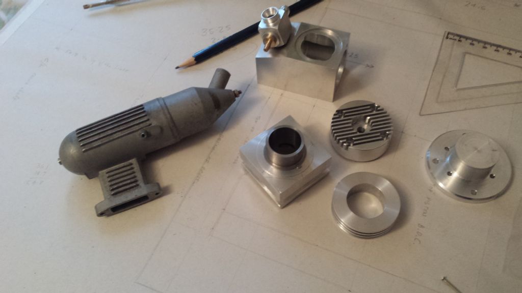
                          firefly parts

                          #270188
                          geoff walker 1
                          Participant
                            @geoffwalker1

                            Hi Jason and all,

                            Returned to the firefly recently, a photo of some of the parts in the previous post. (posted before I added text, doh!!!)

                            The silencer in the photo is off an SC engine and has centre fixing hole spacings at 37mm.

                            The whittaker drawings show 35.5mm. spacing for the silencer bolt holes. I assume this is to accommodate an OS silencer which has hole spacings at 1.38" (35mm.) If so that seems odd, why 35.5 why not 35?

                            I am tempted to use the SC silencer and adjust the hole spacings in the barrel to suit although this would of course preclude the use of an OS exhaust at a later date.

                            Justengines online have wide range of silencers at reasonable prices and varying hole spaces including 35 and 37 mm. Has anybody bought a silencer from them?

                            Reading online there seem to a variety of different silencers. Silent, extra silent? I would be interested in any opinions on silencers particularly ones suitable for the firefly.

                            Posted the photo again here. I have shortened the barrel and modified the liner to accept a removable aero sleeve. The head has also been modified as can be seen in the photo.

                            thanks to all geofffirefly parts

                            #270201
                            John Rudd
                            Participant
                              @johnrudd16576

                              Justengines are a reputable company, I've bought from them in the past, including silencers….

                              As for silent and extra silent, these were borne out of the need for models to be quietened down at noise sensitive sites….complaints from locals to the EA….and even though there were occasions when the sound levels were below the 82db threshhold, folk fitted quieter silencers anyway….this provided a niche market…

                              Edited By John Rudd on 06/12/2016 10:17:57

                              #270288
                              JasonB
                              Moderator
                                @jasonb

                                I'd be temnpted to see if those holes in your sliencer could be elongated slightly so they will fit the 35.5mm hole ctrs, might just need to turn down the screw head dia slightly if they touch the manifold.

                                I have also used Just engines a few times though not for silencers and they were fine to deal with.

                                #270341
                                geoff walker 1
                                Participant
                                  @geoffwalker1

                                  John, Jason,

                                  thanks for your replies, as ever always appreciated.

                                  I think I will buy a 35 mm. silencer from Just engines, they seem like good value.

                                  I don't want to modify the SC box as I may wish to use it again on the SC.

                                  Really enjoying this project, much of the stuff I make requires very little precision.

                                  This engine has been a real challenge. Can't see an a completion soon, sometime in early the new year, hopefully!!!

                                  thanks again geoff w

                                  #280098
                                  geoff walker 1
                                  Participant
                                    @geoffwalker1

                                    Hi Jason, John and all

                                    More questions if I may.

                                    The piston design has a blind hole for the gudgeon pin. Is there any reason why?

                                    My view, albeit from limited experience, is that if you drill and ream (5mm) right through for the pin you will accurately size the hole for a 5mm silver steel pin. The pin could then have a bronze cap at both ends.

                                    I assume the cap is to protect the liner in the event of the pin sliding laterally in the hole.

                                    Why does the cap have a hole down the centre?

                                    Best to all Geoff

                                    #280114
                                    JasonB
                                    Moderator
                                      @jasonb

                                      I've done them both ways so no problem if you wanted to do a through hole and caps both ends. There is also another vartation where you don't run teh reamer right through which allows the pin to be pushed into the hole and held by the taper left by the reamer. Some engines have the blind hole if the pin is likely to pass over a port in the cylinder liner as you don't want the pin snagging.

                                      I've also done solid and drilled caps, think the reason for the hole is that any air trapped within teh pin at assembly could expand as the engine gets not and push the pins against the liner

                                      #280419
                                      geoff walker 1
                                      Participant
                                        @geoffwalker1

                                        Thanks Jason, good information.

                                        Just the piston and con rod to make then lapping and fitting, lots to do but I think the finish may well be in sight.

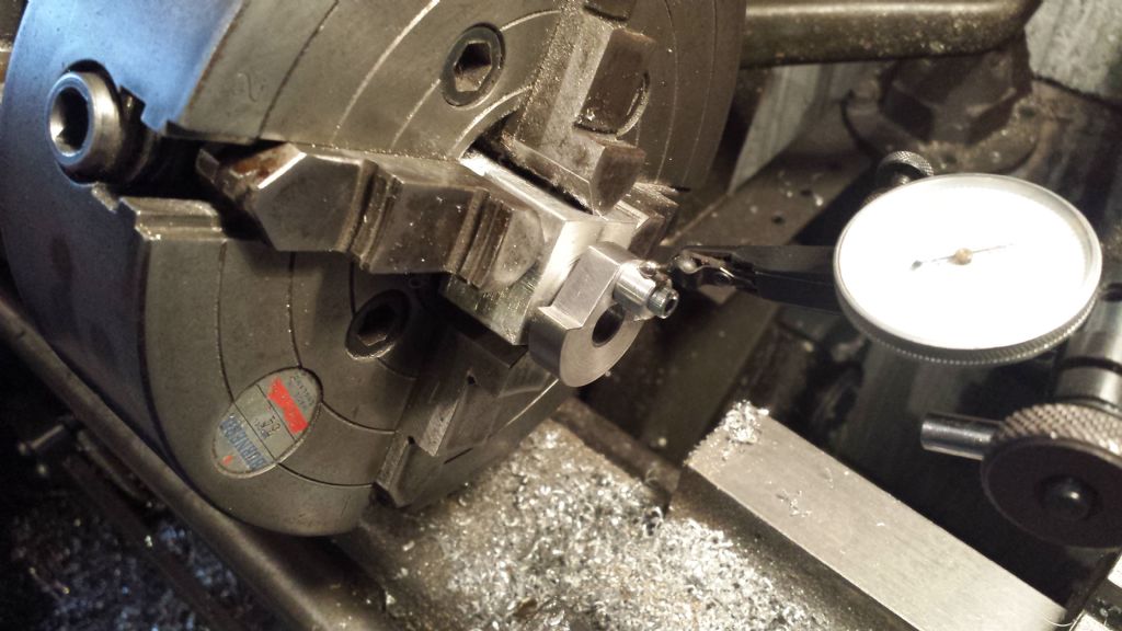
                                        I finished the crankshaft today drilling the hole for the crank pin.

                                        I read your blog build notes first, glad I did, a 5.5 hole is a good press fit for 7/32" silver steel.

                                        Photos show set up for drilling the crank pin hole using toolmakers button

                                        atb geoff

                                        #290225
                                        geoff walker 1
                                        Participant
                                          @geoffwalker1

                                          Hi Jason/John and all,

                                          I've had a long break from my firefly but started work on it again this week.

                                          Lapped the liner, made the piston and lapped it into the liner. Just the gudgeon pin and the conrod to make and I can commence assembly.

                                          Gudgeon pin is easy enough but a question if I may about the conrod.

                                          The centre line of the crank pin boss, side view and the centre line of the waist, also from the side view lie on the centre line of the liner. Correct?

                                          The gudgeon pin boss is offset, more on one side of this centre line than the other. Why is that?

                                          Also which side of the gudgeon pin boss faces the front of the engine?

                                          Best Geoff w

                                          #290231
                                          JasonB
                                          Moderator
                                            @jasonb

                                            It allows for a thicker crank web. Being thicker the rod is further back so the offset is used to centralise the rod in the piston.

                                            Thicker end to the front of the engine

                                            #290246
                                            geoff walker 1
                                            Participant
                                              @geoffwalker1

                                              Thanks Jason.

                                              Just measured again, the following from my previous post is inncorrect

                                              The centre line of the crank pin boss, side view and the centre line of the waist, also from the side view lie on the centre line of the liner. Correct?—— No INNCORRECT

                                              The centre line of the crank pin boss is in fact offset from the centre line of the liner by 0.7 mm to the rear of the engine which accounts for the offset off the upper boss.

                                              I'm glad I asked that question the answer has been most helpful.

                                              First crap weather day we get next I'll make a start on it.

                                              Not tomorrow though sunshine all day a spin up the M6 and a day Blackpool.

                                              I have more questions but will leave them till next week.

                                              Thanks you very much geoff

                                              #290828
                                              geoff walker 1
                                              Participant
                                                @geoffwalker1

                                                Hi Jason

                                                I have decided if possible to not make the needle valve assembly and buy one instead.

                                                I have found this one on ebay but not sure if it has the recommended needle os24081970.

                                                Is the right needle important, would this assembly do the job

                                                regards geoff

                                                http://www.ebay.co.uk/itm/OS-Engine-Needle-Valve-Unit-Assy-40-46-65LA-26582900-/262770588512

                                                #290829
                                                JasonB
                                                Moderator
                                                  @jasonb

                                                  Should do the job

                                                  #290835
                                                  geoff walker 1
                                                  Participant
                                                    @geoffwalker1

                                                    Thanks

                                                    #292674
                                                    geoff walker 1
                                                    Participant
                                                      @geoffwalker1

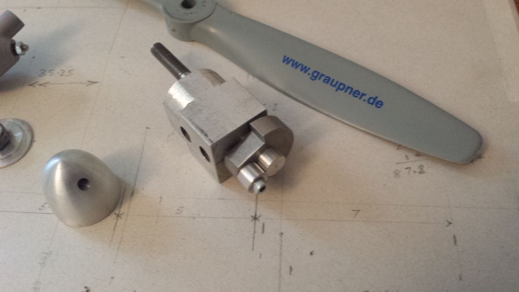
                                                      parade of partsHi Jason,

                                                      Firefly is all finished and assembled.

                                                      Once again, many thanks for your help and a superb build thread.

                                                      Pictures below. I have modified it a little with a shorter barrel and a removable aero sleeve and slimmer head. The head is slightly larger in diameter to accommodate wider hole spacings for the head bolts. This was necessary to ensure that the threaded holes in the barrel did not foul the transfer ports. The crankcase has deep groove ball bearings front (8) and (12) rear and the crankshaft has a conventional keyed drive for the prop driver.

                                                      Just a show pony at the moment, have not run it yet, that's another story.

                                                      A few final questions please. Was/is there any final consensus on the type of plug, prop, fuel etc. which is good for this engine. I have never started one before so I am now on another learning curve. big T again Geoffcomplete firefly

                                                    Viewing 25 posts - 76 through 100 (of 170 total)
                                                    • Please log in to reply to this topic. Registering is free and easy using the links on the menu at the top of this page.

                                                    Advert

                                                    Latest Replies

                                                    Viewing 25 topics - 1 through 25 (of 25 total)
                                                    Viewing 25 topics - 1 through 25 (of 25 total)

                                                    View full reply list.

                                                    Advert

                                                    Newsletter Sign-up