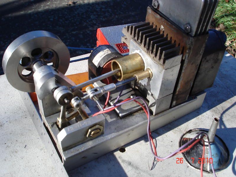
Jan Ridders Horizontal Stirling ‘Bas’

Advert

Jan Ridders Horizontal Stirling ‘Bas’

Home Forums Stationary engines Jan Ridders Horizontal Stirling ‘Bas’

Viewing 25 posts - 51 through 75 (of 112 total)
  • Author
    Posts
  • #222158
    pgk pgk
    Participant
      @pgkpgk17461

      I decided to leave the flywheel centre for the moment while i decide whether to try and masrk the couple fo small dings I managed to make in the spokes. the nly cosmetic way i can think of would be to fill with a film of solder. Since the base parts are supposed to be soft soldered too i had a practice with available stuff on some scrap.

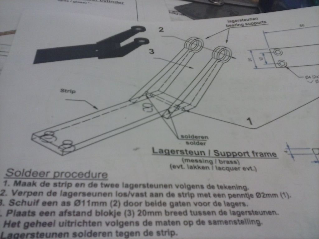
      Yes I can soft solder metal using cored solder but it's all but impossible to hold the parts accurately for that base unless i spent a while making a purpose-built jig. Probably unnecessary work so I've gone with a though bolt m2 and JB weld. The height of the bearing holders above the base is given and I found a block to sit it against while it sets up that was spot on. Once set it'll clean up and hopefully be the correct angle(s)

      cam00440.jpg

      If I have a go at floating solder into the spoke digs then with cored solder i need to avoid a direct flame. I'm thinking of a block of scrap held on a thin rod and heated to red.. then place against the two offending spokes for heat transfer – like the old fashioned soldering irons. Another job put off for the moment.

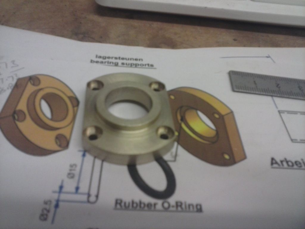
      I have knocked up this part:

      cam00439.jpg

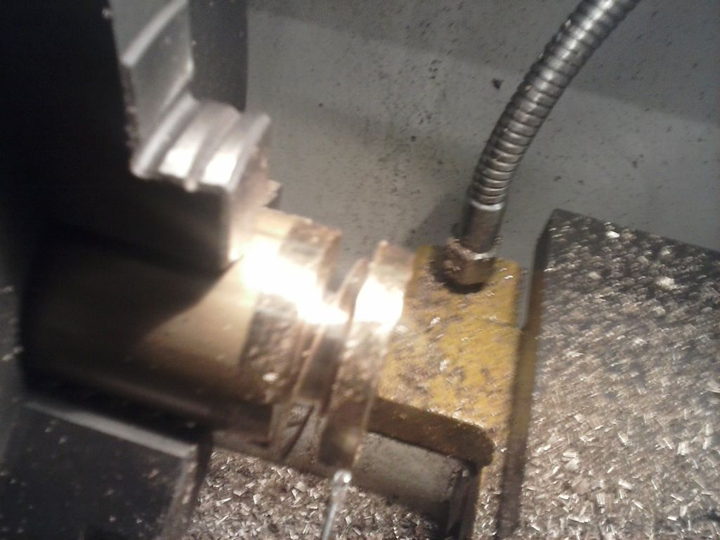
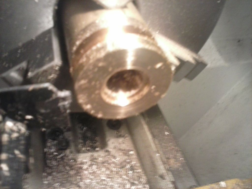
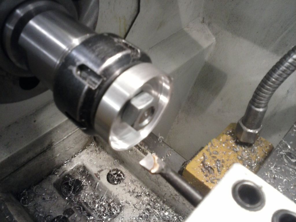
      the quick way by turning to diameter, boring out the boring the recess, using a wide parting tool to the raised section depth by DRO numbers and then parting off to length, milling the flats and drilling the bolt holes. That was much easier than last time when i turned the part and re-centred 4-jaw for the opposite end work.

      cam00438.jpg

      cam00437.jpg

      I think i'll knock out some small parts next

      Advert
      #222228
      Ian S C
      Participant
        @iansc

        I think I would have a go with some JB Weld or similar to fill the dings in the fly wheel. If the FW is cast iron it could cause you some problems soldering it, ok if it is steel, or bronze, it would solder easily. Coat of paint, and only you will know there was any problem.

        Ian S C

        #222232
        pgk pgk
        Participant
          @pgkpgk17461

          My phone cam images don;t do justice to the finish on the flywheel rim.. really is close to a mirror finish (luck) and made from a plate of hot-roll. I was trying to avoid paint or any filler would do. It's only a couple of cosmetic dig-ins on the spokes.

          I did also wonder about brass coloured leafing of the spokes for contrast. it's not just gold leaf one can buy.

          If brass wasn't so mucking expensive and making that flywheel time consuming I'd remake in brass. but then there's risk the project never gets finished….

          the original plans also show a brass cosmetic base below both the night-light holder and main pillar.. but again the brass cost is silly as shown…possibly could look the same cheating with a brass sleeve instead of solid pad.

          #222718
          pgk pgk
          Participant
            @pgkpgk17461

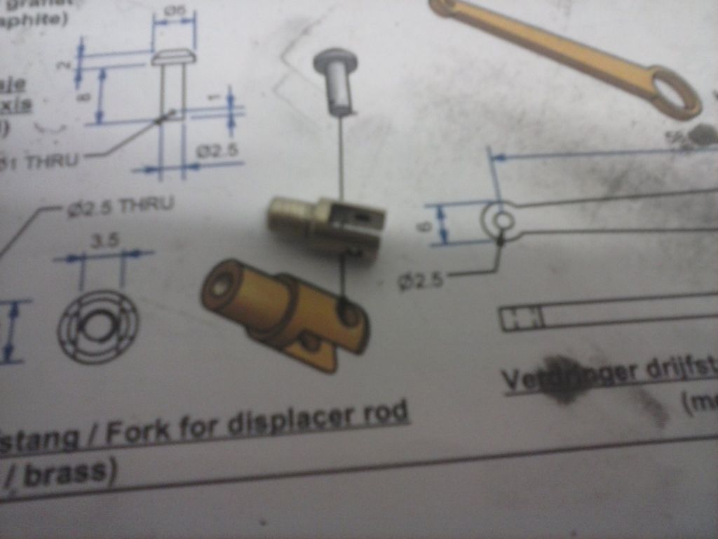
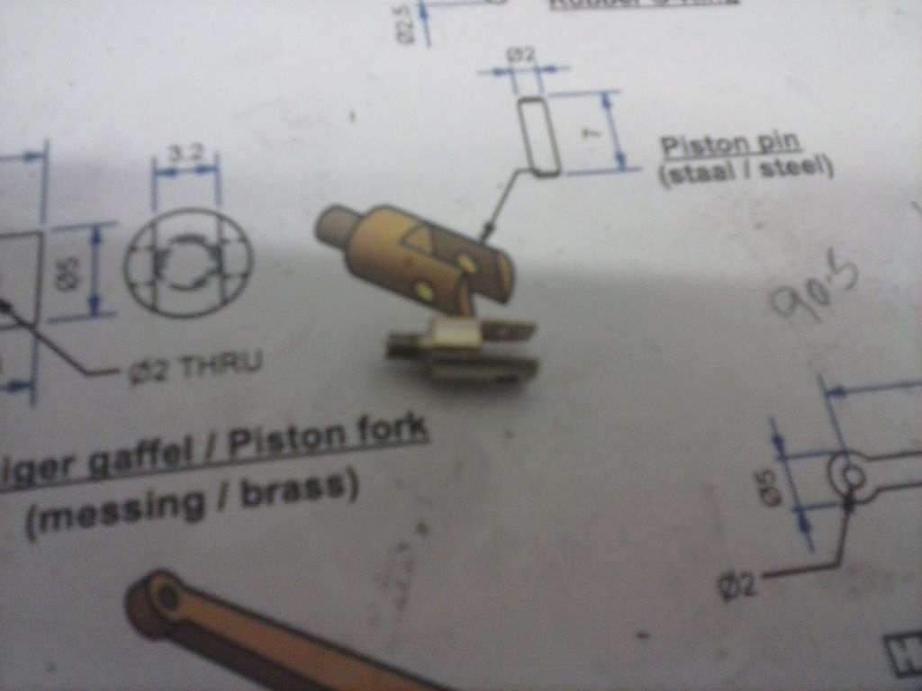
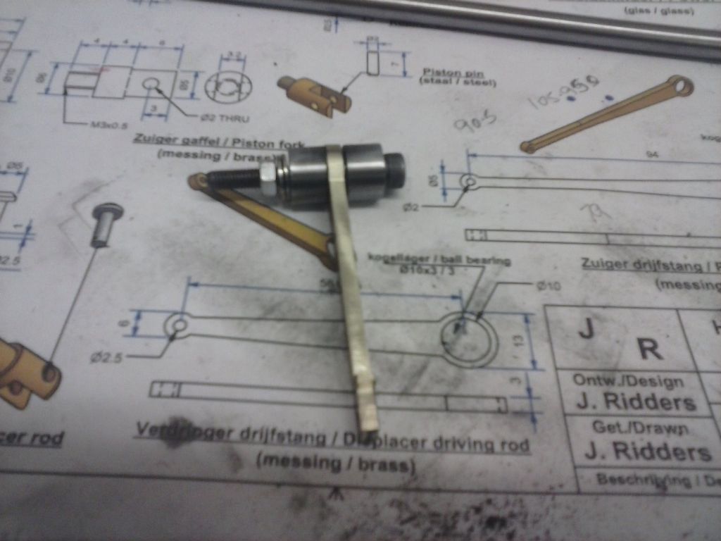
            Next up were a couple of small brass linkages. I suppose they're gudgeon pin insert bearings for the pistons.

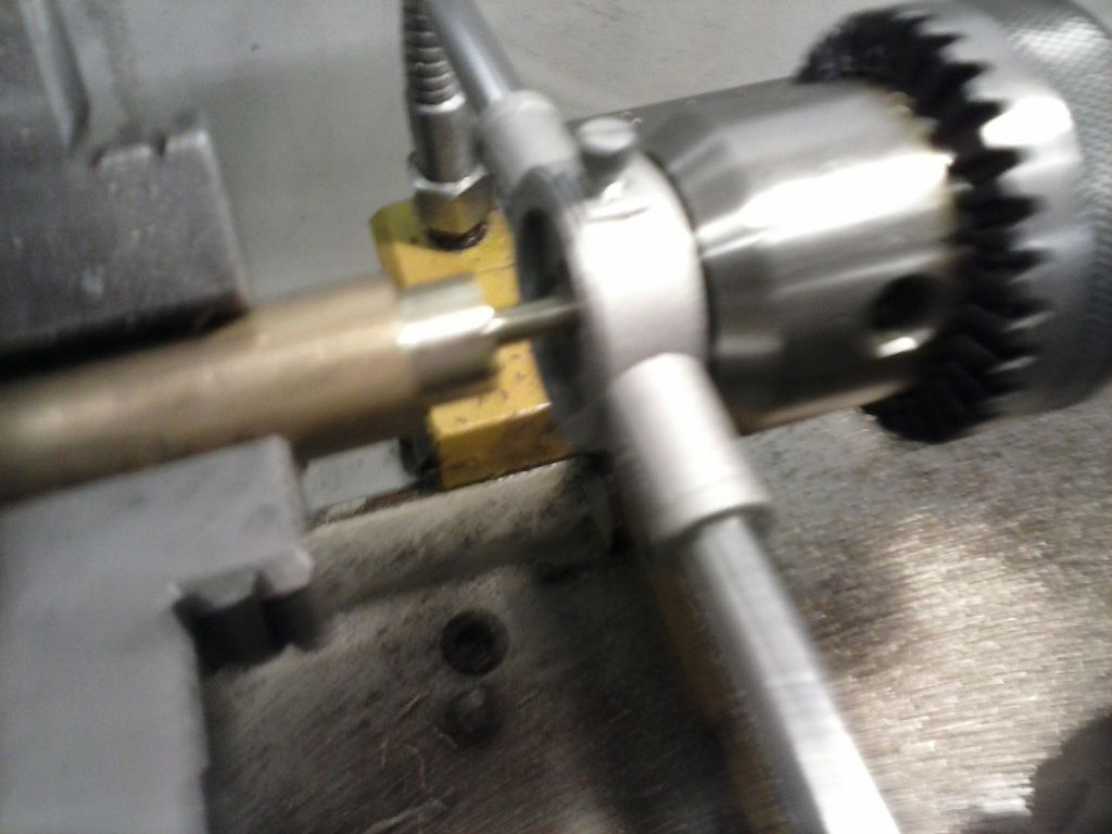
            What a pfaff making tiny parts! I need new smaller fingers! the turning was easy enough and then cross drilled. To setup in the mill for their slots I popped the drill bit through that hole and used a square to set-up the hole at 90degs to the slot to be cut..then shallow cuts due to the unstable setup. But it worked OK. the only problem was that i then had to wedge a bit of scrap and paper in the slot before refixing in the er32 collet on lathe to centre the thread cutting (tap and die).

            cam00446.jpg

            cam00447.jpg

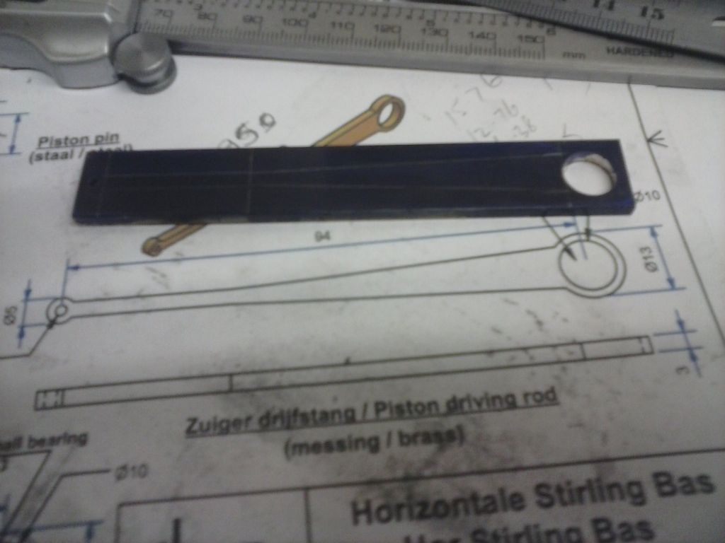
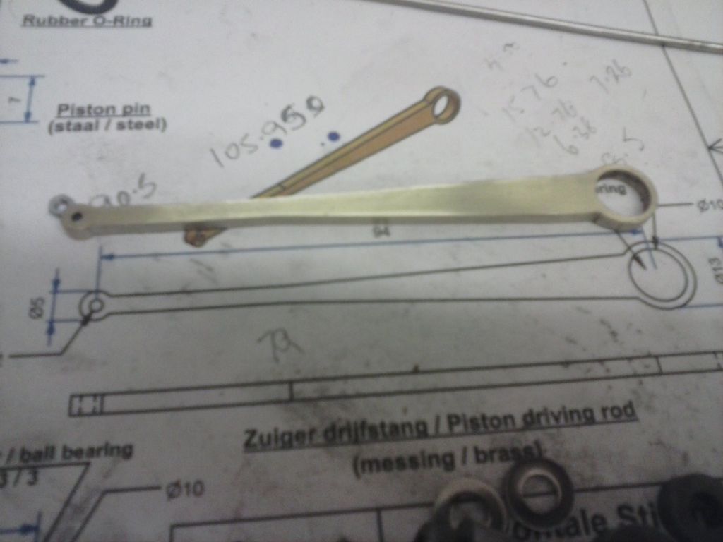
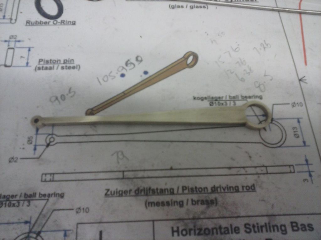
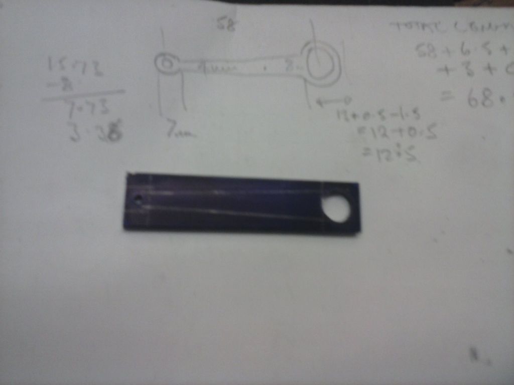
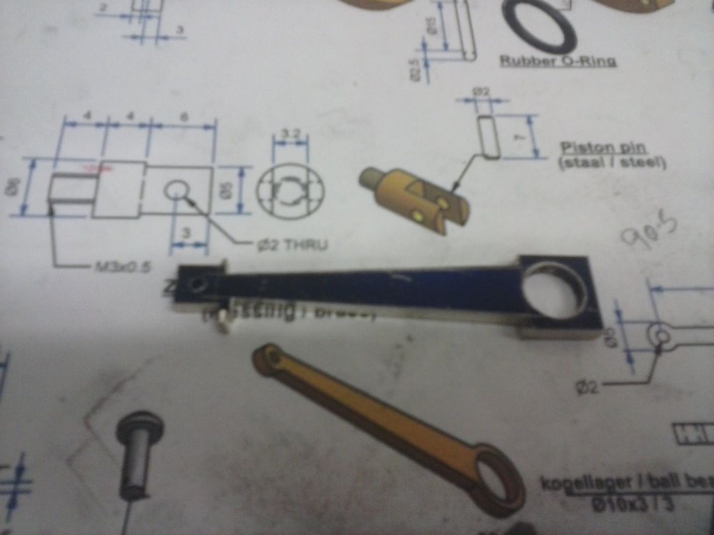
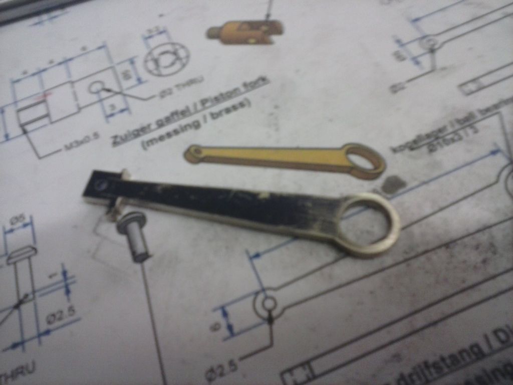
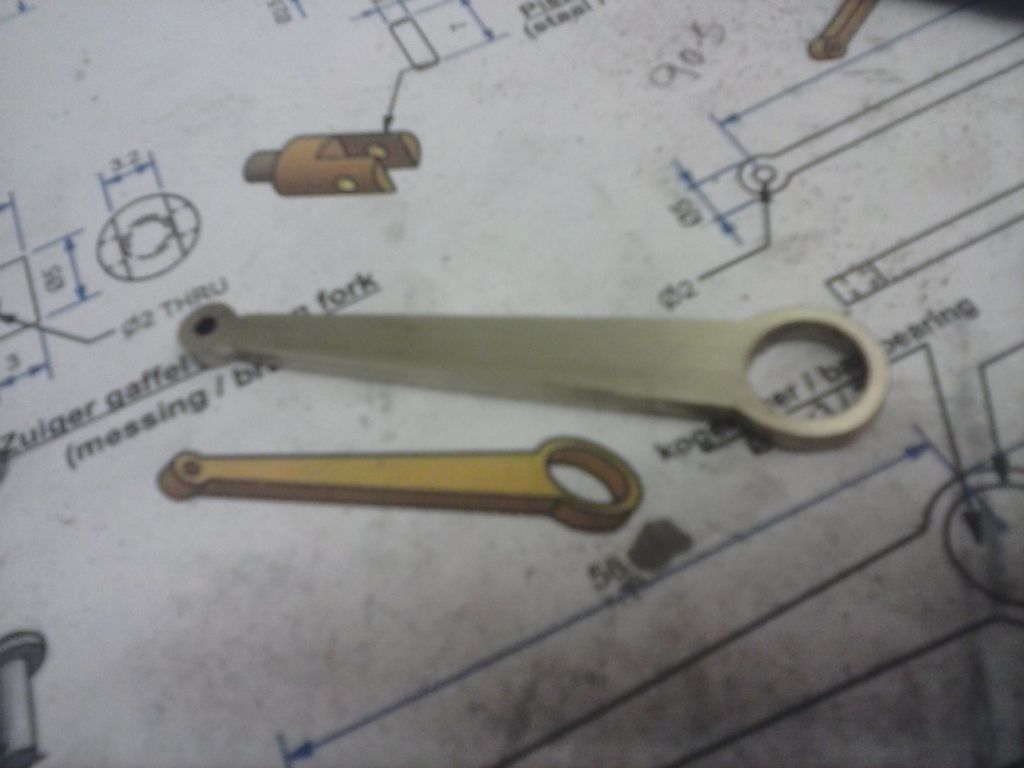
            Then i had a go at the first conrod. I spent some 5/6 hours over two sessions on that..cut and milled to length then blued and layed out, holes drilled and hogged the majority of waste on on the mill, then makiong up the two sizes of filing buttons from silver steel and hardening and filing. And not happy with my result It's just not even both sides of the midline and will have to be done again. I can't see a way of cheating it howveer functional it may be…

            cam00441.jpg

            cam00444.jpg

            cam00445.jpg

            #222878
            pgk pgk
            Participant
              @pgkpgk17461

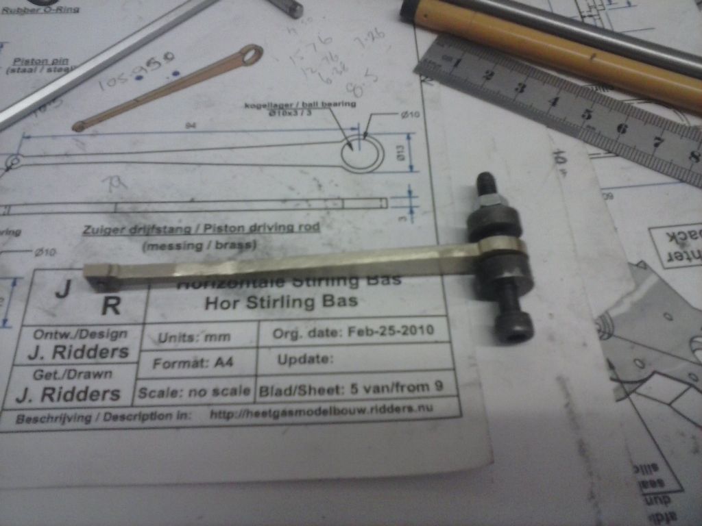
              I made another of the long crank. Whilst I got the body of it neater I wasn't as happy with the ends. Perhaps one day I'll finally get to file neatly and make some more:

              cam00448.jpg

              The on to making the shorter crank. the same process and again lots of care and time but a result I'm not that proud of.

              cam00449.jpg

              cam00450.jpg

              cam00451.jpg

              cam00452.jpg

              cam00453.jpg

              they look better in the pics than in real view….

              #222983
              pgk pgk
              Participant
                @pgkpgk17461

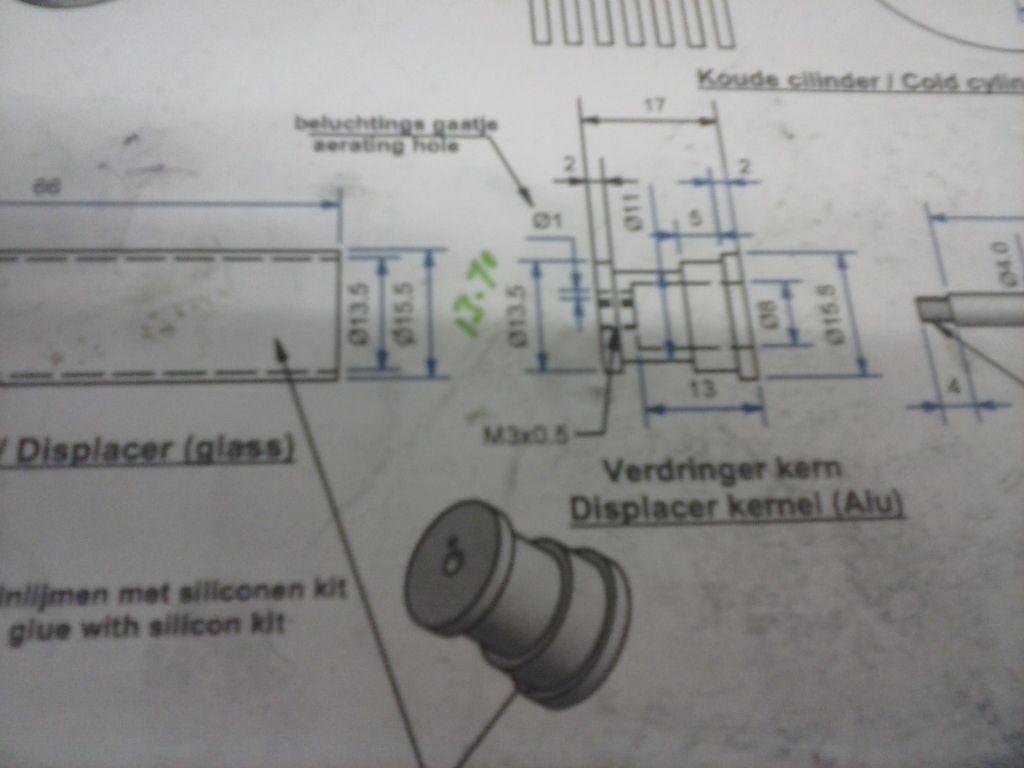
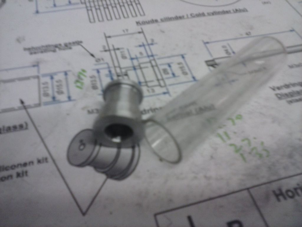
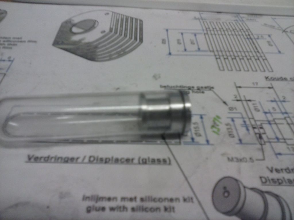
                The next item is the displacer 'kernel'.. the plug for the con-rod link.

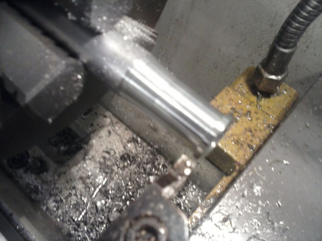
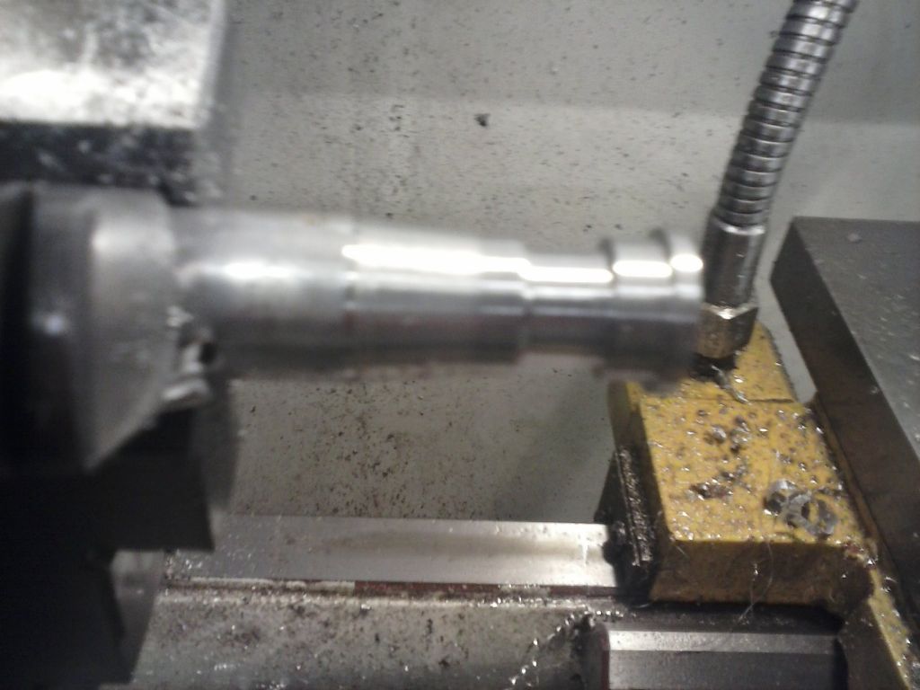
                the outer dimension is the same as the displacer glass..so i bought 16mm ally rod which measures the same as the 15.5mm glass!!..so just skin it true in the 3-jaw. 5/100mm off the diameter did it.

                The nuisance with this part is that it's drilled from the flange end but one wants to test-fit the smaller diameter into the tube. I don't trust my measurements with a bore snap (which gives me 13.70mm) so I'll turn a section to that to check.. then discard….And for a change my measurement was spot on.

                The 8mm hole really needs to be flat bottomed and I don't have a boring tool that small…hmm..drill to 7,5mm then use an endmill..it's only ally…and a cheap 2-flute endmill.. After the centre-drill and 5mm I went to a 2.5 and drilled well beyond length and tapped M3 by hand with a machine tap – should keep it all on centre. Then a 7.5mm drill. No probs with the slot drill, hand de-burred and show the hole edges some scotchbrite.

                I've not tried outward turning before. I figured the options were to make a wide parting start groove, use a steep tool angle or as I did ramp in from nearer the chuck. I'm getting such a good finish with this indexable tip and angle I didn't want to change it. Done. I went 1/100mm under my number. I hope it's a nice fit.

                I'm 5/100mm under on the groove diameter but it's only a glue groove so I shan't fiddle.

                That was a close fit.. had to wipe it with scotchbrite before it'd go.

                The hardest part was the vent hole.. supposedly 1mm and just to the side of the threaded portion. My smallest drill was 1.5 and a bit of a dodgy setup in the mill too..so gently drilled. it's fine. the central square bottomed hole is supposed to be 13mm deep. it turns out that despite my care it's not fully flat-bottomed..sides are 12.49mm deep across the centre 12.96mm. iIcan sort that if needed by chamfering the con-rod link.

                cam00454.jpg

                cam00455.jpg

                cam00457.jpg

                cam00458.jpg

                cam00459.jpg

                #223005
                Ian S C
                Participant
                  @iansc

                  pgk pgk, one thing I do with con rods like your's, I drill a row of holes down the centre line, I make them about 1/3rd the width of the con rod. It reduces weight, but is probably more ornamental than anything else.

                  Ian S C

                  #223007
                  pgk pgk
                  Participant
                    @pgkpgk17461

                    I agree.. and depending on the arc of movement it'd have been a lot smoother at the ends to file the roundings flush to the bar rather than bringing that circle further round… the bit I had trouble filing neatly. Plus you'ld end up with more brass filings from your drill holes.. always useful mixed with epoxy to fill splits in decent woodworking projects with ornamentation.

                    But I'm trying to follow the drawings where practicable..the exceptions being the brass sub-bases and the brass flywheel (cost grounds)

                    Also i should hav emeasured that flat bottomed hole while it was still on the lathe instead of trusting the tailstock markings for depth and checking when removed – Doh – kiddy mistake!

                    #223118
                    pgk pgk
                    Participant
                      @pgkpgk17461

                      I made the carbon displacer piston today. No point in a pic 'cos with my camera it's just a black blob. the displacer tube isn't parallel along it's length..narrows to the open end so while the piston slips in nicely it sticks..and may have to get scotchbrited to a slight taper or perhaps some form of honing but the stuffs quite soft so perhaps just working it will do…?

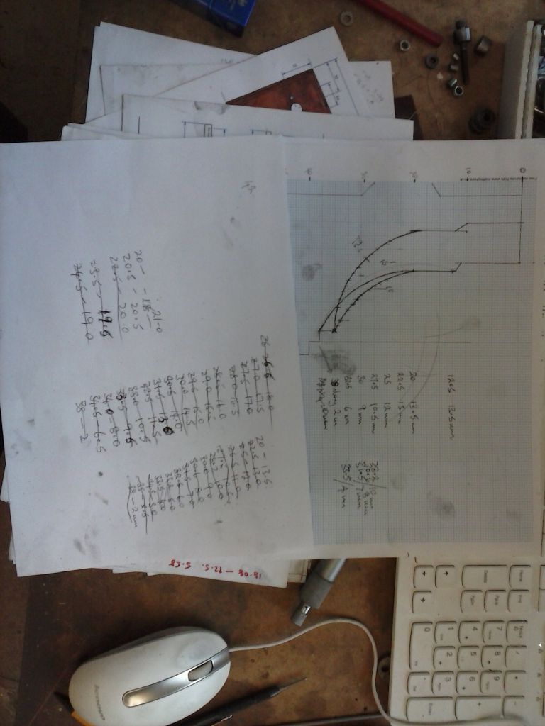
                      Next will be the stands…at the mo I'm playing with graphic layout to work out some coordinates for roughing the curve on the lathe for a filed finish. If one could use a metal lathe and ally with hand held tools like on a wood lathe this would be quick and easy….

                      #223207
                      Ian S C
                      Participant
                        @iansc

                        To reduce the diameter of the carbon plug, spin it and use a strip of paper in the same way you would use emery cloth on a bit of steel. I imagine that Jan uses graphite here because of its light weight.

                        It is possible to to use hand tools on the metal lathe, I clamp a bar in the tool post, and have been known to use one of my wood turning scrapers on aluminium, and brass.

                        Ian S C

                        #223214
                        pgk pgk
                        Participant
                          @pgkpgk17461

                          Thanks, Ian, your comments do help.

                          I'm guessing any hand tool used would be a narrow rounded fnishing scraper rather than any sort of gouge..

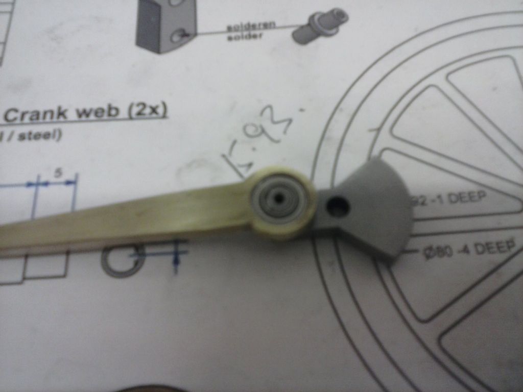
                          I've also found another issue.. the drawngs call for a 3mm stud on the crank webs going into the conrod bearings. I made it all to size and used red threadlock on those studs. looking up to buy the recommended bearings: od 10mm, id 3mm width 3mm – non such listed by 2 major bearing suppliers. Closest are 4mm and 5mm id's.

                          I don't want to cook my threadlock loose..it's going to discolour those crankwebs at the temps needed so I'm going to have to sleeve the studs OR use a bearing in a bearing. I'll dig about in my rc heli spares bins (I crash a lot) and see what's about….

                          EDIT: I don't have any but thinking about it ne of those round indexable tips on a bar would make a good metal scraper??? 'Capt Eddie' on youtube uses them on wood too..

                          Edited By pgk pgk on 30/01/2016 14:32:04

                          #223332
                          Ian S C
                          Participant
                            @iansc

                            Brian, if the hole in the bearing is too big, just make a little bush to fit inside the bearing, with a hole to fit the shaft, I had to do that on my smallest motor when I ran out of bearings with 3 mm bores.

                            You can modify the tip of an old file as a scraper (and still use the file).

                            Ian S C

                            #223342
                            pgk pgk
                            Participant
                              @pgkpgk17461

                              And i thought I was having a bad day ….I'm not Brian and sleeving the shaft is the same as bushing the bearing

                              On to the first stand..and my turn to have senile moments…

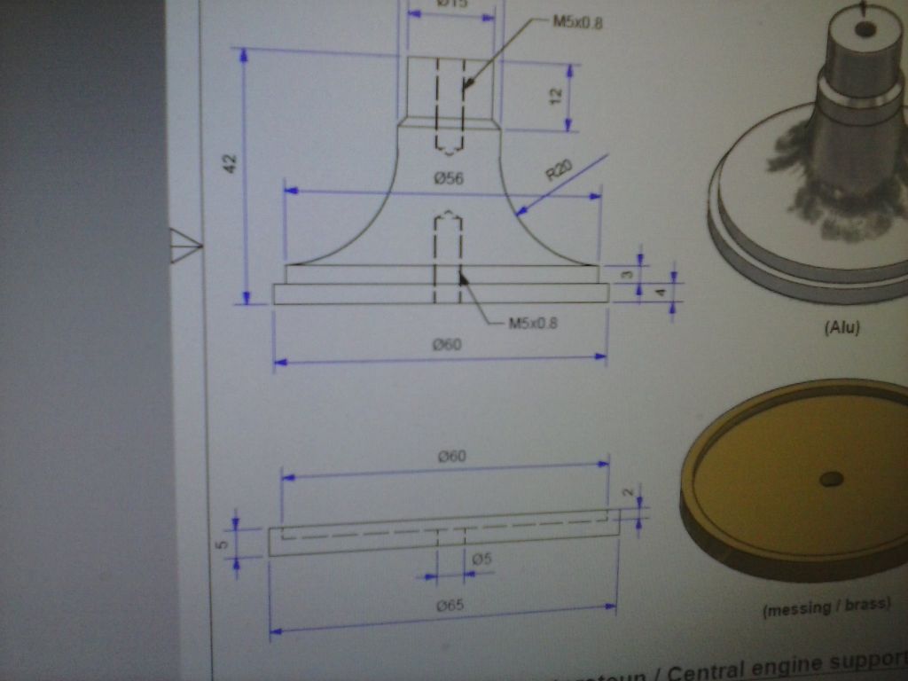
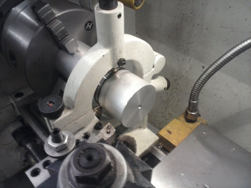
                              I'd drawn out the profile on graph paper and worked out the coordinates. I didn't want to cut my large ally bar and waste the holding end so decided I'd have to use tailstock and a fixed steady to drill for that. This was on the limits of my lathe.. the gap bed means you can't mount the fixed steady close to the head and to have tool access i had the steady only 2/3rd on the bed and the last 1/3 hanging over the gap..but it worked.

                              cam00462.jpg

                              cam00465.jpg

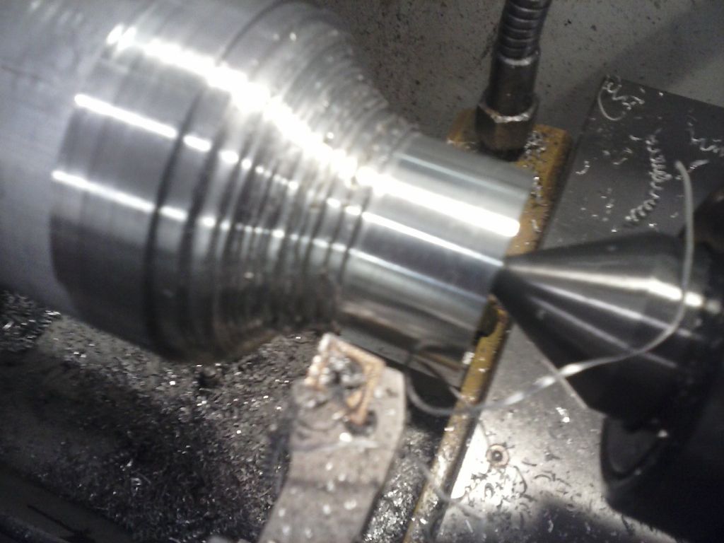
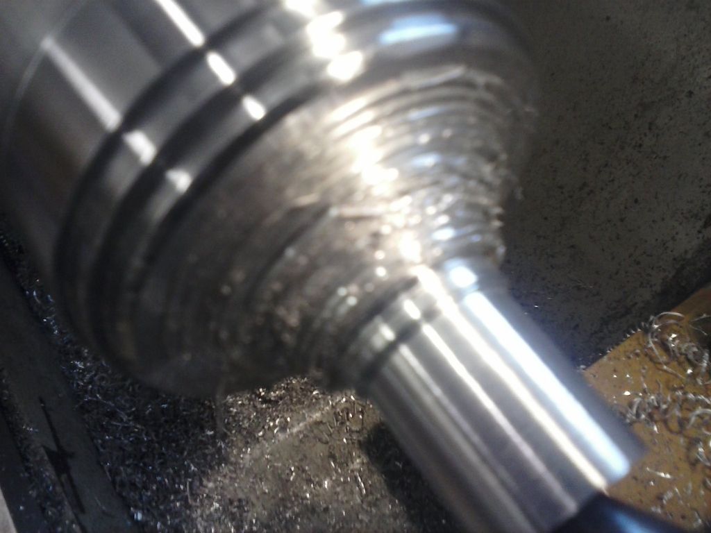
                              I happily ran the lathe to the worked out coordinates… a long slow plod with swarf everywhere..

                              cam00466.jpg

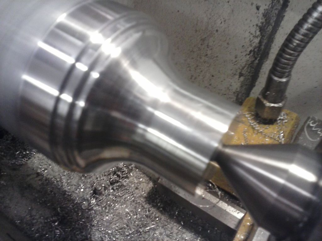
                              Then started blending it all in.

                              cam00467.jpg

                              What with file cleaning and emery work it wasn't quick. Just when i thought I;pd done I realised I'd made a mistake on my drawing – a half profile and stupidly drawn the top distance full width instead of half.. modify the drawing and new coordinates..

                              cam00473.jpg

                              The redo the part to the deeper coordinates..

                              that's when my senior moment really kicked in and near the end i brain-f@rted and wound the cross-slide in instead of out..and gouged it!.

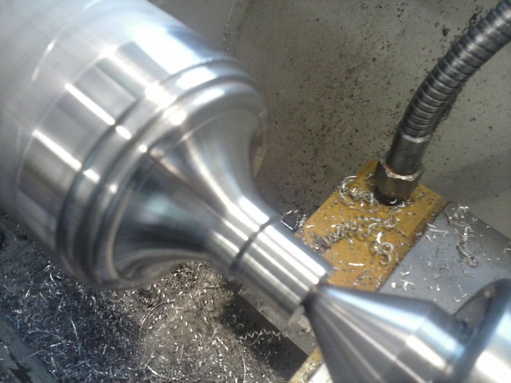
                              the options were to start again or since the part is purely decorative then use artistic license and blend my error in..

                              cam00468.jpg

                              cam00469.jpg

                              OK it's not exactly to drawing but looks pretty good to me.

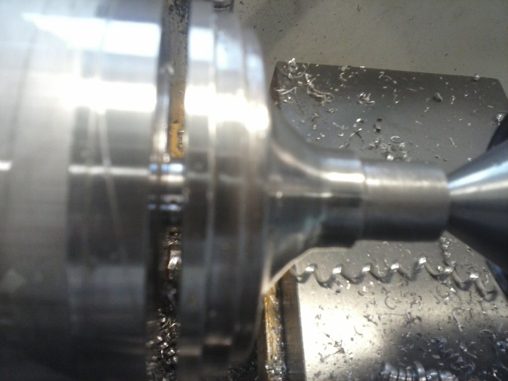
                              Then parting… I didn't have the courage to try and go right through with a tailstock on there and it was tending to get sticky on the tool at depth but did go some 26/27ml deep on teh radius

                              cam00470.jpg

                              I really do like indexable parting tools..

                              After that it was hack-sawed adrift and reversed into a collet for skimming the base and the base thread

                              cam00471.jpg

                              Now to spend several hours cleaning up….

                              Edit:

                              I should add that the extra base step is instead of the separate brass sub-base..to save the brass cost.

                              Edited By pgk pgk on 31/01/2016 13:25:07

                              #223829
                              pgk pgk
                              Participant
                                @pgkpgk17461

                                A bit of an update.

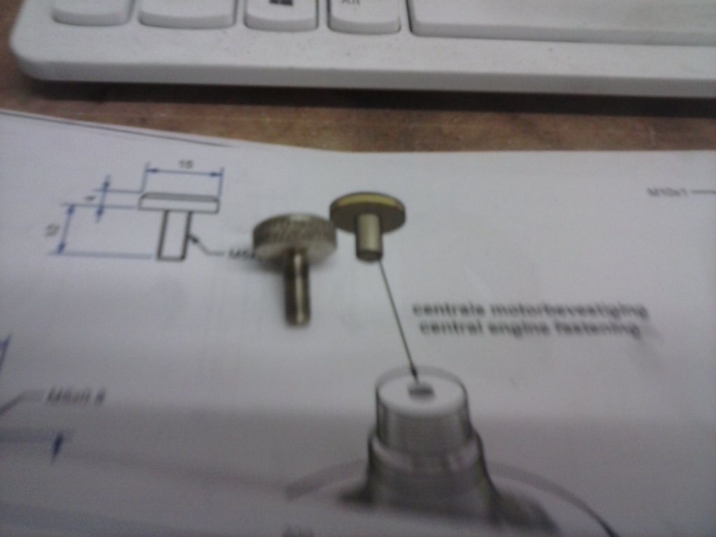
                                The brass screw for the top of the main plinth.. a simple turning and threading exercise but I did add a simple knurl using my 'tom's techniques frame knurler:

                                cam00474.jpg

                                cam00475.jpg

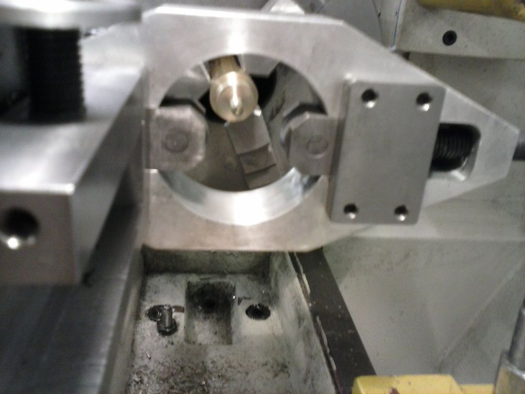
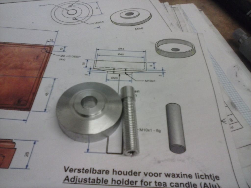
                                Then the candle holders.. again a simple enough bit of turning although i had a mare over the threaded rod..m10 fine and I made a mistake trying to use silver steel which felt harder than usual… perhaps hardened more during grinding? And my tool I honed up had too much flat on the tip for a fine M10. I also tried to cut too deep per pass and caused chuck slippage..and so on. The fourth attempt was on ally with a partial lathe threading using a triangular indexable tip and chased with a die…ho hum.

                                cam00476.jpg

                                cam00477.jpg

                                cam00478.jpg

                                I also solved the problem for bearing sizes (see earlier threads) by digging about in my bearing box and finding id 3mm od 6mm to fit inside id 6mm od 10mm..neat, huh?

                                cam00479.jpg

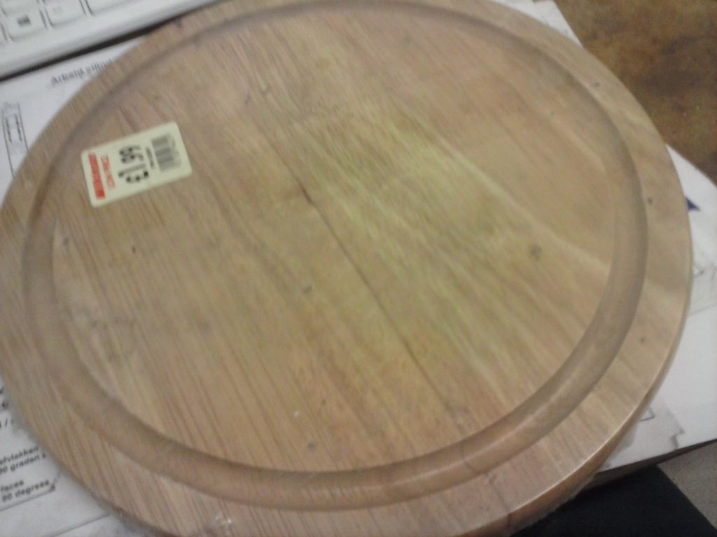
                                then the baseboard.. I bought a bunch of these years ago when fitting up cctv onto pebble-dashed walls..pre-varnished backboards (breadboards) from wilco and still have a few.

                                cam00480.jpg

                                It'll need some feet making..

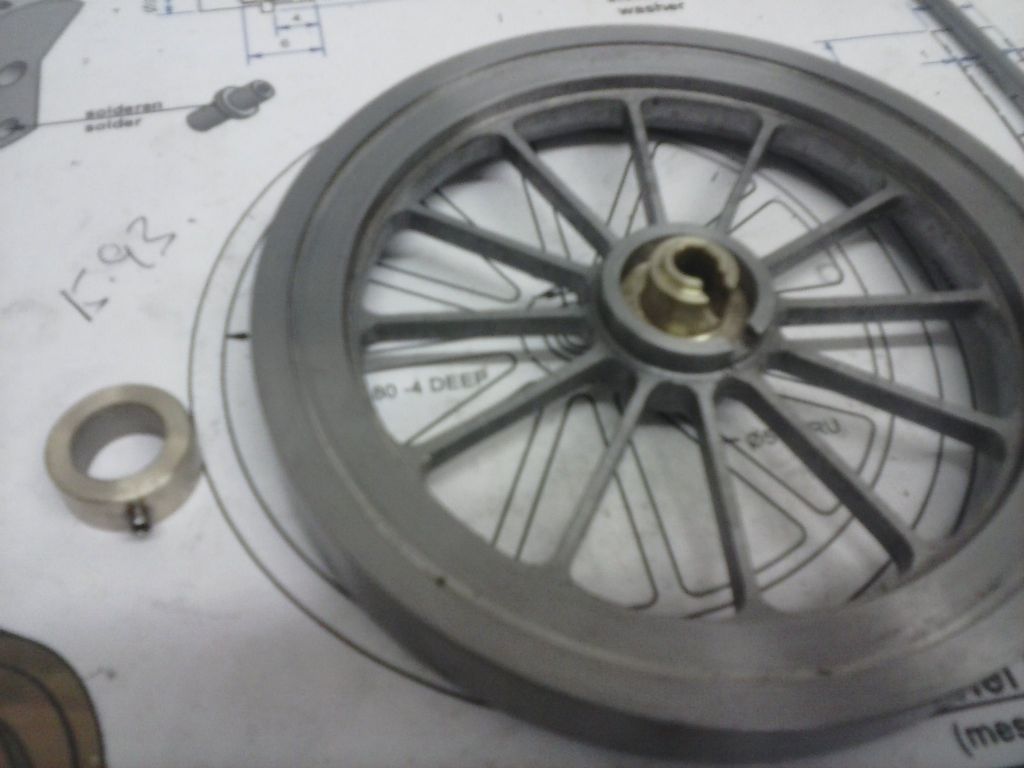
                                Then there's the flywheel boss to sort and a few more small parts pre-assembly

                                Edited By pgk pgk on 03/02/2016 20:47:49

                                #223966
                                pgk pgk
                                Participant
                                  @pgkpgk17461

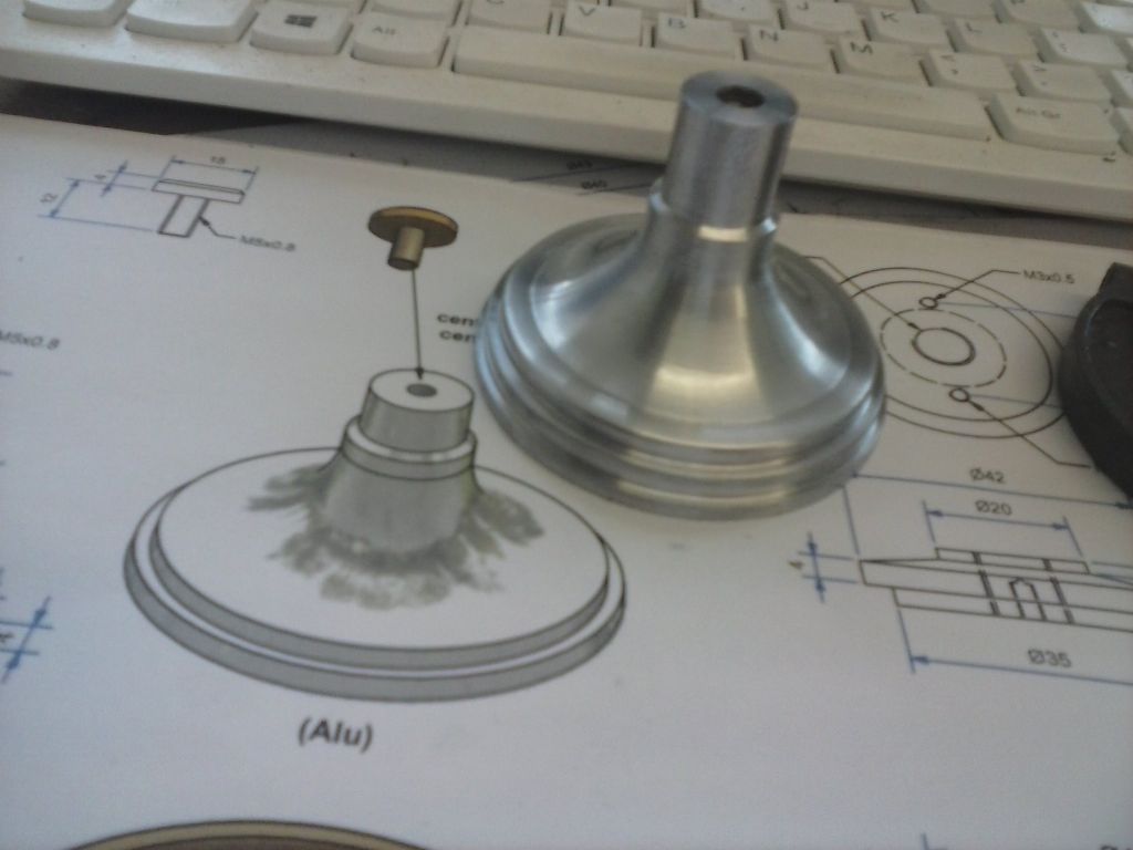
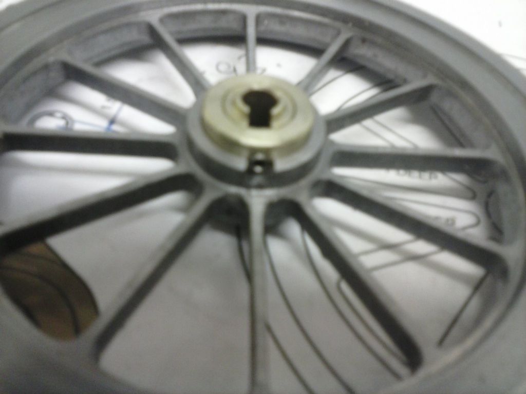
                                  I was stressing over the flywheel boss and how to do it.. so got on with it. first attempt i went slightly undersize for a press fit but second one was good.. pressed in nicely and then the fastening ring to make.

                                  I can't say I like that arrangement unless the fastening ring is locktited in. In any event I went up to an m3 grub screw instead of the drawn m2..mostly 'cos I needed to cut a slot and smallest 2-flute was 3mm.

                                  It's one way to save on metal when the boss is thicker than the rim

                                  cam00482.jpg

                                  cam00483.jpg

                                  #224078
                                  pgk pgk
                                  Participant
                                    @pgkpgk17461

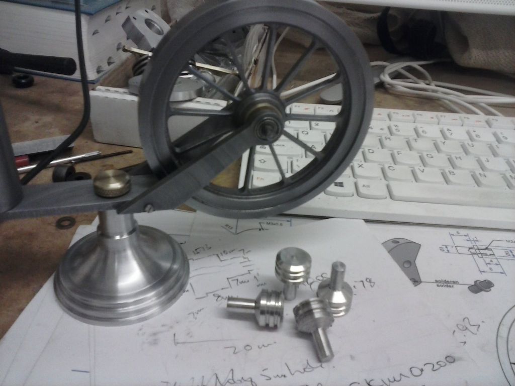
                                    ..finished off the flywheel with it's shaft and test-fitted. Also made 4 feet for the stand..something quick and simple to make off the dro numbers after faffing about with my vertical ball turner and giving up 'cos it needs a lot of clearance from the chuck which isn't good on thin stock and it's not easy to setup for quick reproducibility. as in one would need to cut slugs and remount onto another thicker rod and make separate plinths..

                                    ..just the baseboard to drill and start assembly and fettling..

                                    cam00484.jpg

                                    #224800
                                    pgk pgk
                                    Participant
                                      @pgkpgk17461

                                      cam00486.jpg

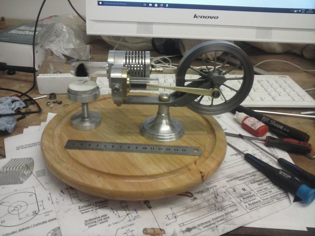
                                      All assembled with a few minor issues..most notable that the power cylinder o ring seat could do with deepening or the cylinder gets pushed out when it's cover is dogged down. I did temporarily set it in with silicone..seems to hold well. But unsuprisingly the thing doesn't run. the only slight rubbing sound is from the shaft of the displacer going through it's bronze bushing.

                                      Having built the thing the potential for leaks in this design is huge and the glass parts just aren't high tolerance so things like the glass displacer may well vary from builder to builder..not that I have any idea on ideal gap between it and wall. The power piston glass perhaps could be lapped with diamond powder for a more consistent fit?

                                      It would have been nice if it did work but was built more for the exercise in doing something to drawings.. and I learned a lot. Working or not it's likely destined to gather dust in a cupboard and not be used…

                                      If it had run (or I get it running) then I did have a plan to fill the small marks on the spokes and paint the spokes gold and polish and lacquer the rest.. but shan't bother on a non-runner.

                                      It's a workshop tidy and catch-up next then come back to this with soapy water and look for leaks, sort out that o-ring seat and perhaps lap a new power piston.

                                      #224873
                                      Ian S C
                                      Participant
                                        @iansc

                                        Some times you just have to sit down and go through every thing, then try it, there is often very little stopping it going, and after you have got a sore wrist from flicking the flywheel, all of a sudden it goes, some times the easy bit is over building the motor, it's just patience that is needed now. Don't throw it at the cat, you'll probably miss, and if you throw it at the dog, it will bring it back to you any way. Don't do as a guy on another forum, he's complaining that the glass parts are melting because he is using a meths burner, and getting it too hot.

                                        If you continue to have problems, it might be worth changing the power cylinder to a metal one, brass tube has a good bore, I'v used it on one of my motors. This one has a 5/8" bore.

                                        Ian S C A little one

                                        #224876
                                        pgk pgk
                                        Participant
                                          @pgkpgk17461

                                          I've had some time to think about it (but got other stuff to catch up on)

                                          Several areas for investigation. Firstly I donlt actualy know which way the flywheel should turn (yeah I'm thick). In cojunction with that i followed the pic assembling the cranks 90 degs apat… but which should lead? Could the drawing be wrong?

                                          Next the system of an o-ring to hold the tubes and seal is a weak point. I've already stated that the power piston ring seat needs deepening… but it may be better to really plug that area with silicone around the rings too?

                                          Any clues as to the best way to lap glass to true the power cylinder bore and the remake a new piston (with a brass cylinder reserve option). I was thinking a brass lap and mix of diamond powder and obstetrical lubricant? Will it true it concentric or just widen it? size of lap compared to cylinder?

                                          Lastly the displacer piston/cylinder sizes are as per jans dimensions but that really looks loose to me…?

                                          #225395
                                          pgk pgk
                                          Participant
                                            @pgkpgk17461

                                            I've never been happy with the power cylinder.. the piston was sloppy at one and and sl tight at the other. Commonsense finally struck and i had 2 spare test tubes so decided to cut a new cyinder from the centre of a tube where the distortions should be least.

                                            This time the cutting went really well..diamond disc in the dremel toolpost and as I cut I added water from a thin rod onto the forming groove.. it just cut through nice and neatly.

                                            As best i can measure with snap gauges it has an internal diameter of 13.70mm with a slight loosening within the bore if the snap gauge is rotated but not difference I can measure so soemehere in the 1-2 hundreths mm???

                                            The piston i already have measures 13.56 diameter. Thin foil 0.08mm and I can only wrap it around 2/3 crcumference to get it in and it's tight so i think the measurements are pretty close. But is that too loose? can i cheat with a smear of silicone grease to contaminate the carbon or would that make it sticky?

                                            At the mo' if i plug the piston thread it falls slower than gravity within the tube with a thumb over the end.. about half speed so probably worth trying before making a new one…

                                            I had to rebore the cylinder support 'cos this tube is slighty wider OD but only by 'touch the boring tool to the bore and run it' I took the opportunity to adjust the O-ring seat which was previosuly too tight as well.

                                            I'm out of silicone sealant that isn;t a blob of hard jelly so need to get soem more. I;ve also ordered some ground 4,mm rod for the displacer conrod ;cos my home turned version just has a tiny drag that doesn't want to polish out. I know that sounds daft but it was made from a gash piece of half inch hot roll and that one area has been a problem throughout turning.. perhaps a bit of slag or inclusion???

                                            The other thing that bothers me is that if I turn the engine over without the power piston then i can't detect any air puff down the connceting hole – using tissue wisps and plucked hair. that hole isn't blocked so either i have leaks or the displacer is too loose…..?

                                            comments welcome

                                            #225467
                                            Ian S C
                                            Participant
                                              @iansc

                                              When polishing the displacer rod, polish it length wise, it will slide better. Don't put anything on the piston, it sounds a bit too loose, but worth a try. There are a number of places to get suitable rods from, printers/scanners, telescopic aerials/antenna. The hot rolled stuff should be quite ok if you can get a reasonable polish on it. On a number of my motors I used either 3/16", or 1/4" stainless tube, and leave the hollow displacer open to atmosphere.

                                              The displacer leads the power piston by 90*, in the photo above it should turn clock wise.

                                              Once a pon a time the medical profession used glass syringes, these were round, and parallel, and each one of the tens of thousands of them was individually matched to its plunger, there is a Japanese gentleman who builds Stirling Engines with syringe barrels for cylinders, but bits of test tube, I'm not too sure how round or parallel that will be.

                                              Ian S C

                                              #225492
                                              pgk pgk
                                              Participant
                                                @pgkpgk17461

                                                Once upon a time indeed… I fully remember boiling glass syringes and hoe they would inevitably leak around the plunger only if you loaded the with something really expensive….heck, we even resharpened needles..and I;m guessing even older f@rts remember the curved glass for sharpening razor blades.

                                                It's just one little patch on that rod that snags and wont polish out – silver steel on order. if I think there;s a leak aroudn that through the bush then I;ll remake the bush and use a section of the rod as a instrument makers reamer and get it closer..

                                                edit. I think the prblem with the tets tubes is that they start as parallel tubing and then there's a distortion when the closed end is rounded and the open end flamed to smooth it. the middle bit should be the least distrubed

                                                thanks..


                                                Edited By pgk pgk on 15/02/2016 15:43:55

                                                #225512
                                                Howi
                                                Participant
                                                  @howi
                                                  Posted by pgk pgk on 14/02/2016 21:12:12:


                                                  The other thing that bothers me is that if I turn the engine over without the power piston then i can't detect any air puff down the connceting hole – using tissue wisps and plucked hair. that hole isn't blocked so either i have leaks or the displacer is too loose…..?

                                                  comments welcome


                                                  Why should there be a puff of air from the displacer piston? That is not it's job.

                                                  Remove the glass displacer piston and blow from power piston end, have you got a free flow of air?


                                                  #225533
                                                  pgk pgk
                                                  Participant
                                                    @pgkpgk17461

                                                    There's no obstruction in the channel between the two cylinders. it's just that if the displacer is supposed to move warm/cold air cyclically between the two then i expected some detectable flow…

                                                    #225611
                                                    Ian S C
                                                    Participant
                                                      @iansc

                                                      You don't really need to use silver steel, stainless is good.

                                                      The displacer doesn't move the air, it just displaces it, the air stays still (more or less), and the displacer alternately fills the cold end (when the air is heated), and the hot end (when cooling).

                                                      Back in the early 1960s Mum used to work in the sterile supply department in the main hospital in Dunedin, where they sharpened needle, both hypodermic, and suture, blades for dermatomes, as well as making up sterile dressings. Up until about 1980, in my job as a nurse, making up and autoclaving dressing packs was a job I had at least one day a week at the country hospital where I worked, then all changed what with AIDS etc. Sorry getting OT.

                                                      Ian S C

                                                    Viewing 25 posts - 51 through 75 (of 112 total)
                                                    • Please log in to reply to this topic. Registering is free and easy using the links on the menu at the top of this page.

                                                    Advert

                                                    Latest Replies

                                                    Home Forums Stationary engines Topics

                                                    Viewing 25 topics - 1 through 25 (of 25 total)
                                                    Viewing 25 topics - 1 through 25 (of 25 total)

                                                    View full reply list.

                                                    Advert

                                                    Newsletter Sign-up