Jan Ridders Horizontal Stirling ‘Bas’

Advert

Jan Ridders Horizontal Stirling ‘Bas’

Home Forums Stationary engines Jan Ridders Horizontal Stirling ‘Bas’

Viewing 25 posts - 26 through 50 (of 112 total)
  • Author
    Posts
  • #215893
    BW
    Participant
      @bw
      Posted by pgk pgk on 09/12/2015 12:30:57:

      Posted by Bill Wood 2 on 09/12/2015 11:16:45:

      At the start of the thread are some notes about cutting glass.

      I've had success with scratching with a glass cutter and then using a soldering iron applied to the scratch and slowly rotated around the scratch on the workpiece – as the soldering iron is advanced the scratch turns into a clean crack

      Bill

      But was that with borosilicate glass? Certainly for ordinary glass creating a weaker point then thermally shocking it can work well… there's suggestions for cutting bottles with accelerant soaked string and tieing around, lighting it etc… or a scratch then pouring boiling water over the area. For ordinary fresh window glass a simple scratch and tap is classic. Along the way before i used the diamond discs I did try scoring and tapping the tubes…just a mess.

      No I didnt use borosilicate glass. I've tried the methods you mention regarding string and ice and thermal shocking and hot wire and cold water etc etc etc. I was trying to find the best way to cut glass.

      The thermal shock methods did not work very well for me.

      Of all of those methods the one I mentioned worked the best for me – and I take your point that it may not work on borosilicate glass.

      However it was also the method that involved the least thermal shock – ie make the scratch and then relatively gentle heating with an electric soldering iron keeping the iron just ahead of the advancing crack. Thats all, no ice or cold water.

      Its fun to watch the crack moving through the glass.

      Is the borosilicate far more difficult to cut than ordinary garden variety glass ?

      Bill

      Advert
      #215895
      pgk pgk
      Participant
        @pgkpgk17461

        The only borosilicate I've tried cutting was these boiling tubes. It was hugely interesting to see the effect of various cutting discs.. the brown and black dremel types essentially melting the glass at the interface from friction.. to the stage of a bright white point of light there- create a groove but never cut through. The whole point of such glass is to cope with thermal 'shock'. It is supposed to have a more flexible molecular structure than ordinary glass – so I'm guessing here – that in a sheet form it either takes a much bigger shock to trigger a crack to run or perhaps at a colder/brittle temp or cut in a semi liquid state with shears??

        It's noteworthy that old glass is harder to cut neatly then fresh glass too. Ancient greenhouse glass is a real pig to recylce by cutting.

        #216059
        pgk pgk
        Participant
          @pgkpgk17461

          Hmm.. this could be the start of a new forum section .. a 'how not to build' thread..

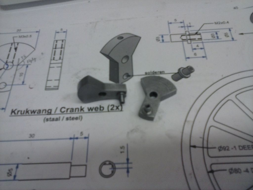
          Yesterday i started on the tiny conrod? axles on the crank webs. Someone was questioning the use of ER32 collet chucks. Well that had to be my way to go 'cos my 3-jaw doesn't grip 3mm.

          The part is 10mm long, 3mm diameter and a 1mm wide flange of 5mm dia 4 mm from one end and an M2 thread in the short end. Talk about fiddly and not helped by my smallest stock being 1/2 inch and just to be awkward whatever variant of mild steel it is I couldn't get a nice finish with power feed on either of two different indexable tip types or two different HSS grinds. The acceptable solution was actually a tediously slower hand feed than the slowest powerfeed option.

          A length of 5mm dia made up eventually and the first part turned out. Rookie mistake again. I turned the 3mm diameters dead nuts then cut the M2 thread..locktighted into the crankweb and discovered that the short end had spread a touch from threading and was now over the 3mm….Doh!

          The second part was turned out ready for tapping..whereupon the centre drill tip snapped off embedded in the shaft. I called it a day.

          Ho-hum. Just remake that second axle. Except that I wasn't happy with the oversize first one so a touch of heat should get it out and adjust. Not with the z-71 red threadlock brand I'd used! By the time i got it out it had blued the steel and the needlenoses had marked it..

          Still i need the practice making this tiny parts….

          #216095
          pgk pgk
          Participant
            @pgkpgk17461

            The practice paid off.. got quite quick at making them at last…

            cam00381.jpg

            #216617
            pgk pgk
            Participant
              @pgkpgk17461

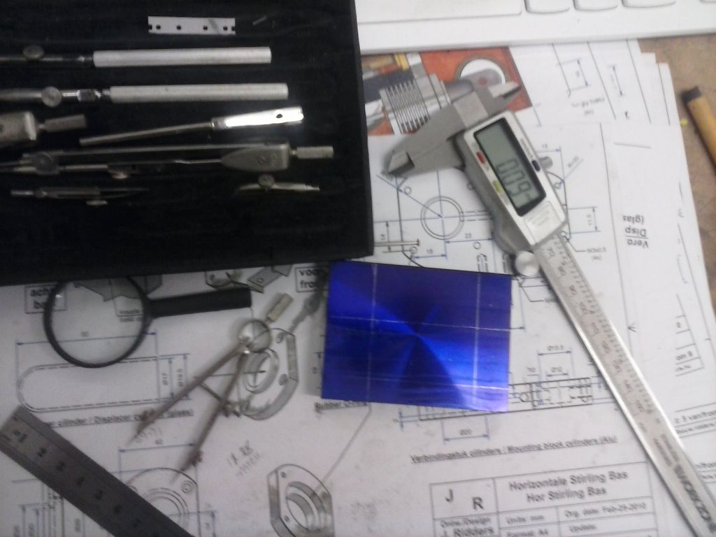
              Ideally i would have made the main block to which all the cylinders attach next but it's quite a busy part and I decided to invest in some layout fluid..post pending.. to reduce the dumbo moves I'm likely to make.

              Shop time has been scarce 'cos wife is away with granddaughter and that leaves me with all the farm and house chores solo and I don't like to abandon the dogs alone in the house for too long at once.

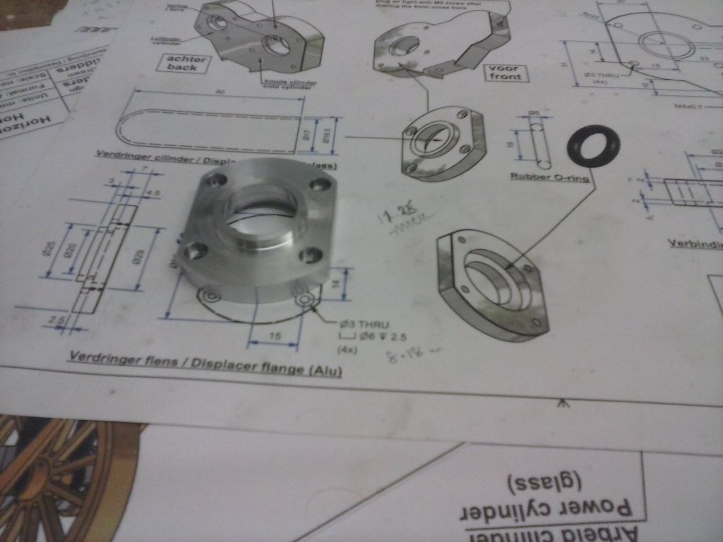
              This was the next part:

              cam00382.jpg

              I had a long think about how to do this. I'm after a mirror finish without jaw marks and aiming for both sides parallel. I'm sure there's lots of ways of doing that…pleased to hear of better ones too.

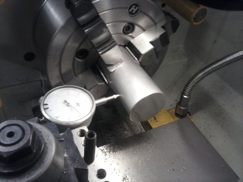
              I decided to use the 4-jaw so i could pop some shims between jaws and part and use the whole length of bar rather than cutting and wasting bits.

              cam00383.jpg

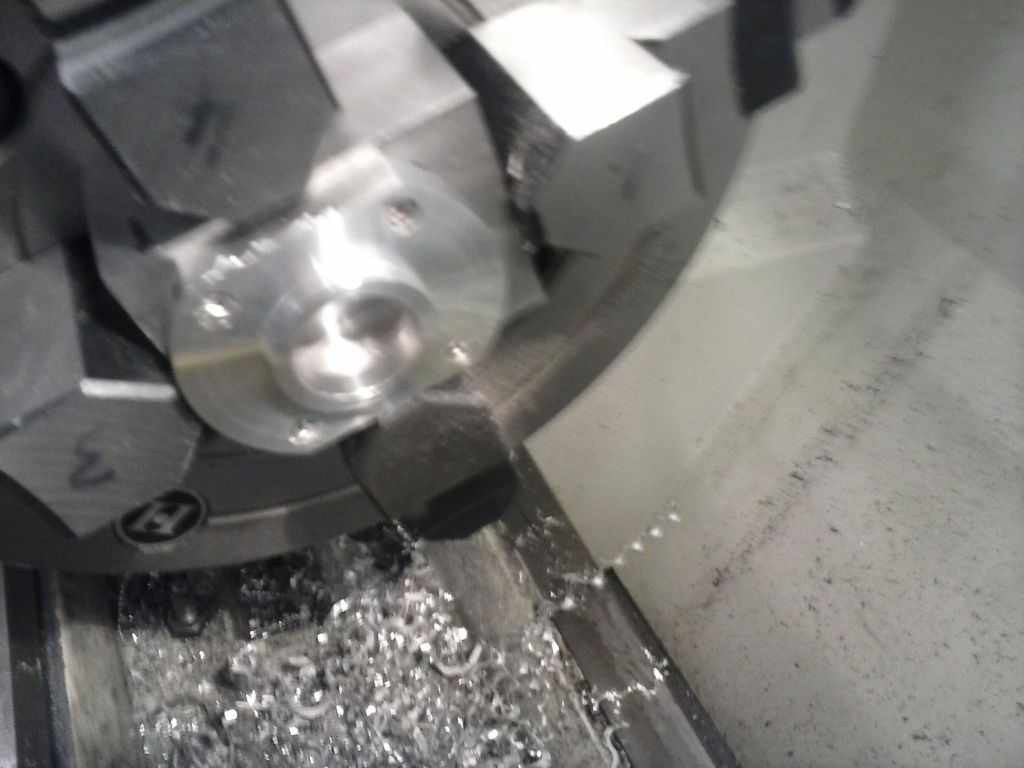
              I got too excited over boring the through hole to take pics but I used one of the boring tools from my mill boring tower fitted into a QCT holder and got a lovely finish. Parted off some 3 mm longer than the drawing and then over to the mill to mill the flats and place the bolt holes with plenty of counterbore.

              I found a squared up scrap block I'd dumbo'd on a different project and drilled & threaded that to bolt too.. indicated in the 4-jaw I got the centre bore set without a flicker on the needle. That worked out well.

              I think the best alternative might have been to make up some soft jaw covers and turn the proud side first with enough to get a grip on but that or fitting it to a mandrel left me concerns that the part might be canted on it's face?? Setting it up on the faceplate would have needed a back board or plate and a mare to indicate compared to the 4-jaw…?

              cam00388.jpg

              cam00389.jpg

              #217385
              pgk pgk
              Participant
                @pgkpgk17461

                This report should be called something like 'how many blunders can you make?'…

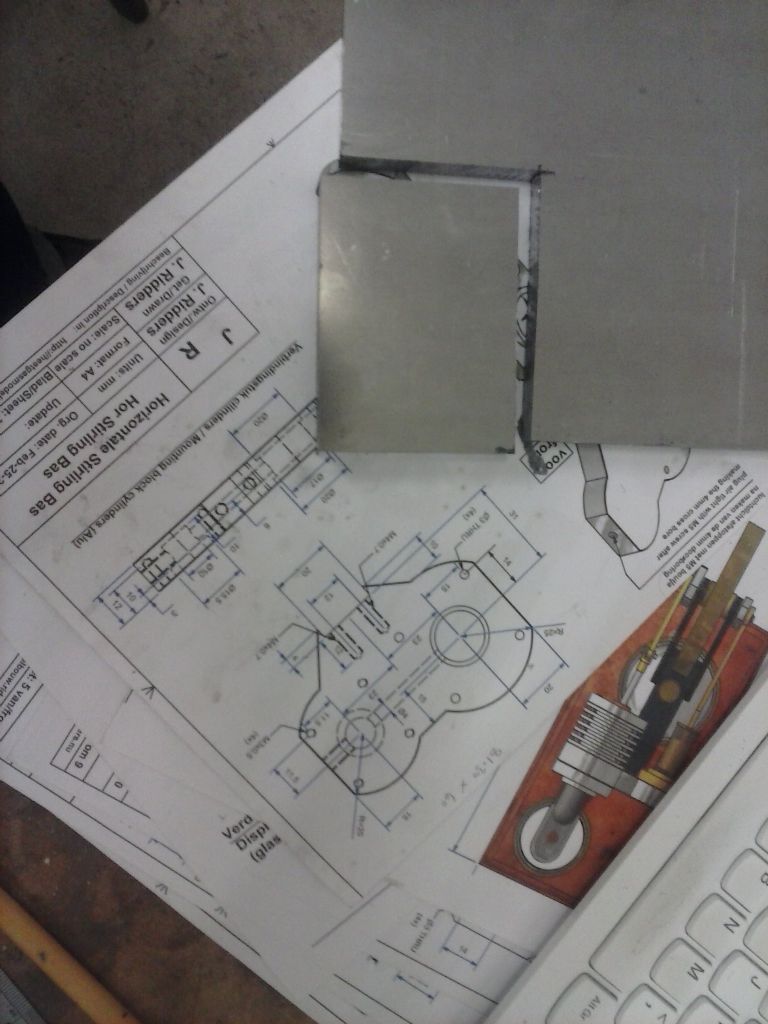
                The main support for the cylinders is quite a fussy part so i decided to play it careful. As you'll see it diodnl;t work out quite as plain sailing…

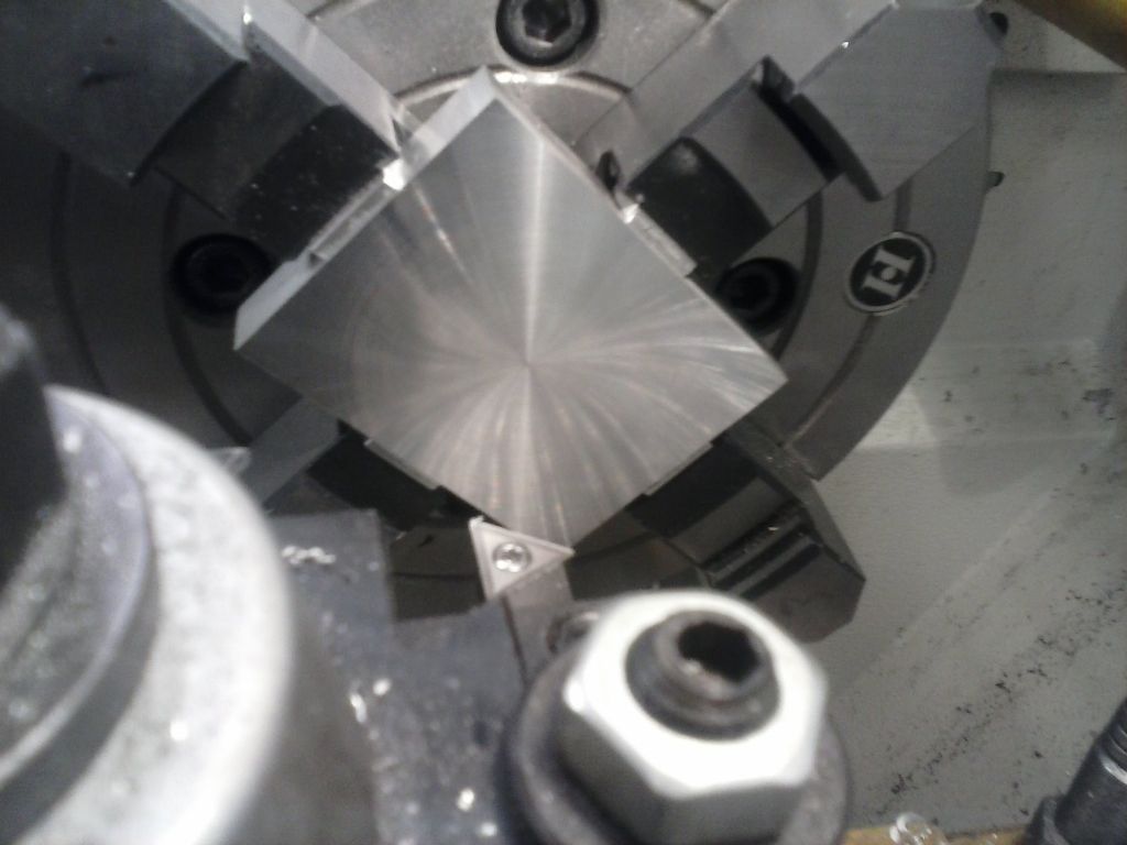
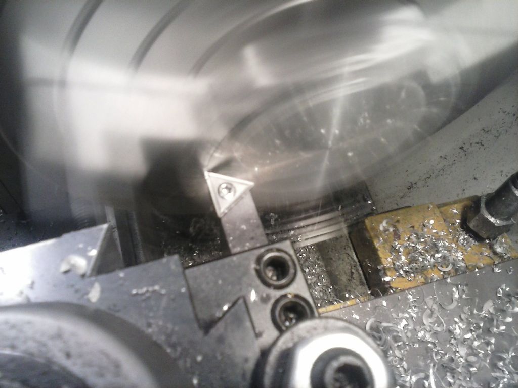
                So a piece of plate bandsawed out and after squaring it up i faced the main surfaces in the 4-jaw to get a better finish- awkward to get the lathe tool in there:

                cam00390.jpg

                cam00391.jpg

                cam00392.jpg

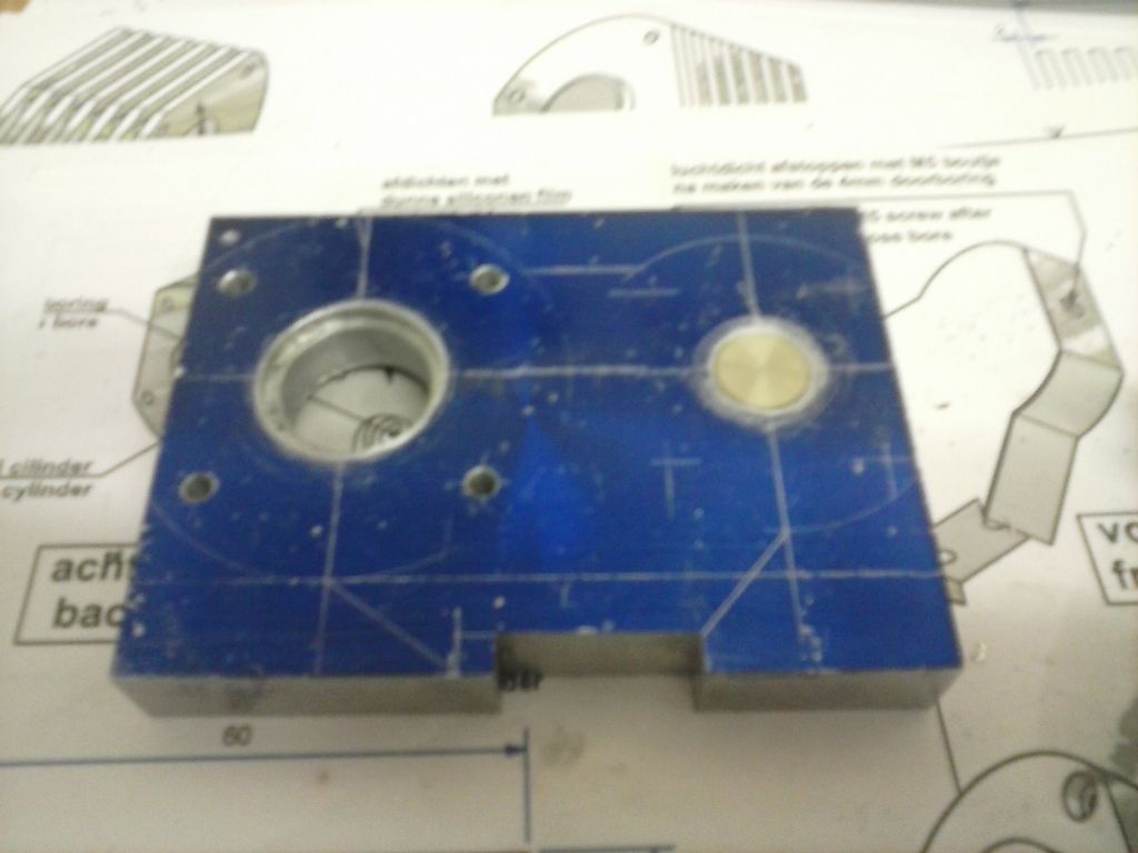
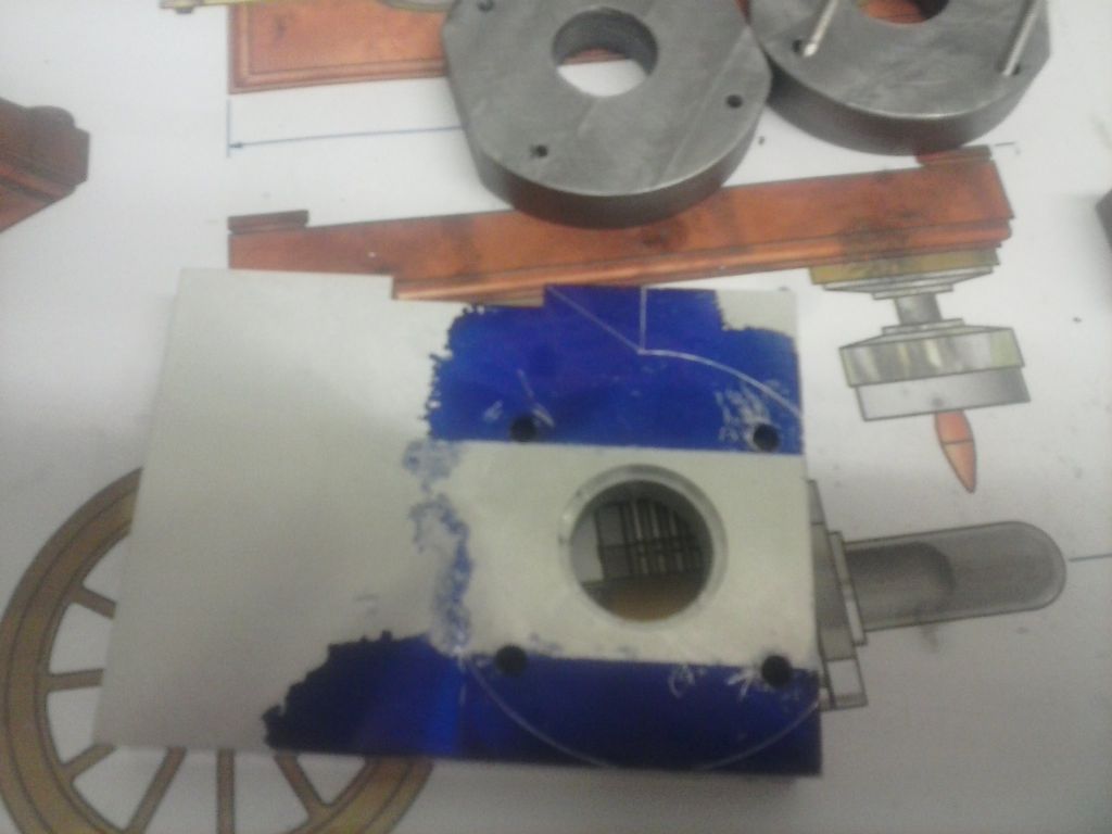
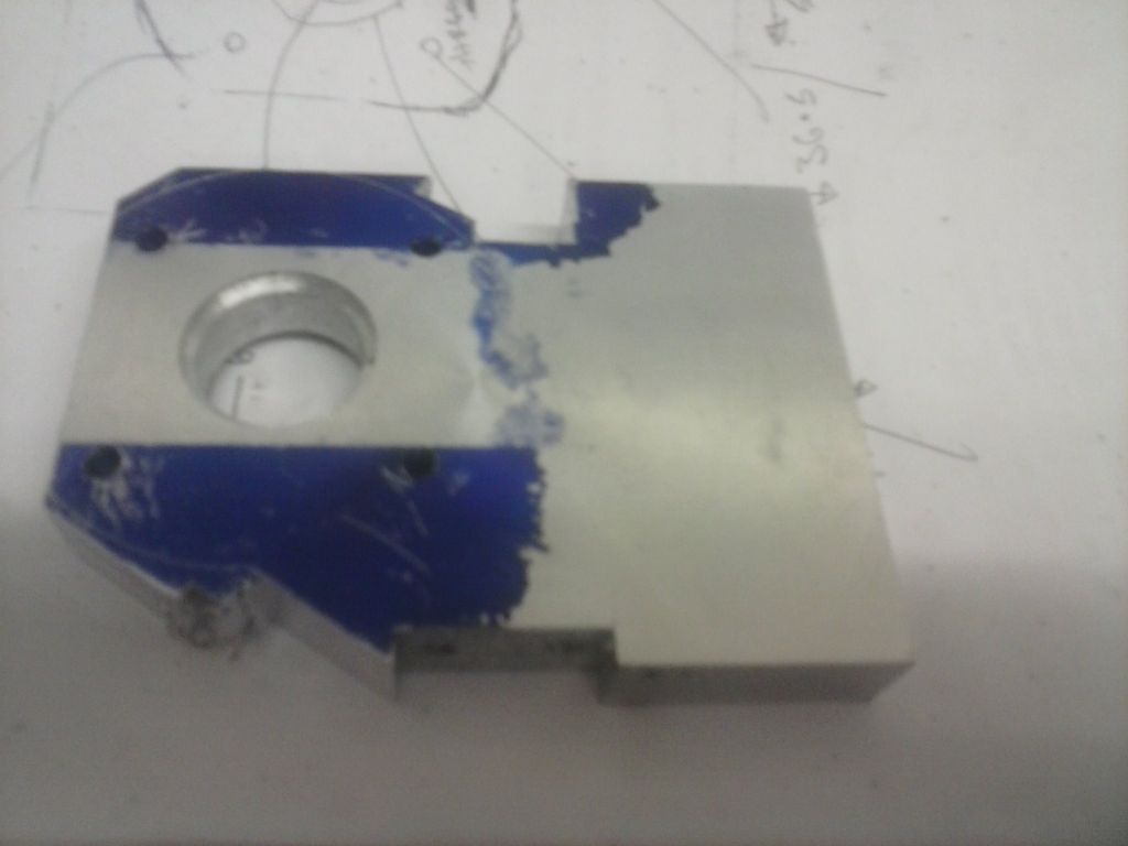
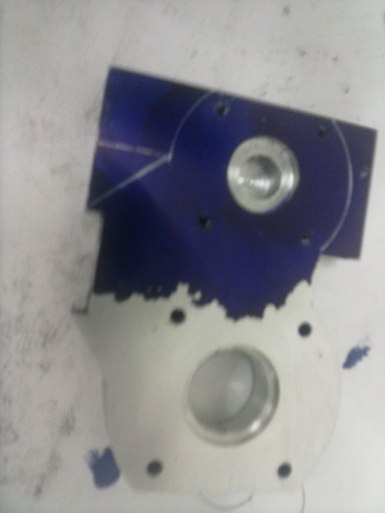
                Then I decided to use my new pot of layout and mark stuff out to avoid bog-ups:

                cam00393.jpg

                cam00394.jpg

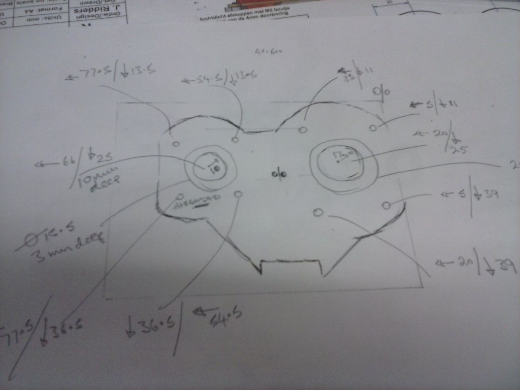
                At least i spotted I'd drawn a mirror image. The concentric circles aren't quite.. but that i excused myself for because I wasn;'t using a pop mark for the compass…didn't want to mark my shiney surface (in case of errors) and anyway I planned to use the DRO..just wanted the layout to help avoid errors (yeah).

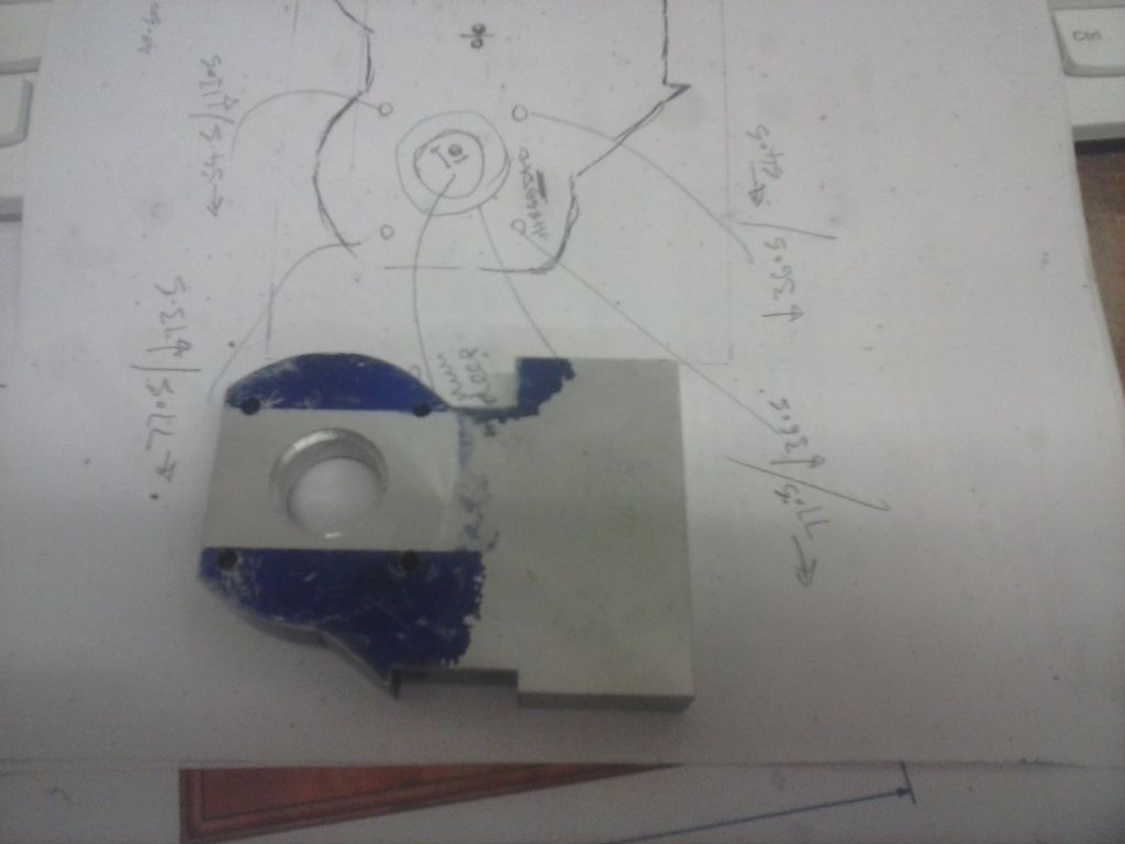
                As a further error prevention I predrew and marked my coordinates all from one reference corner:

                cam00396.jpg

                cam00397.jpg

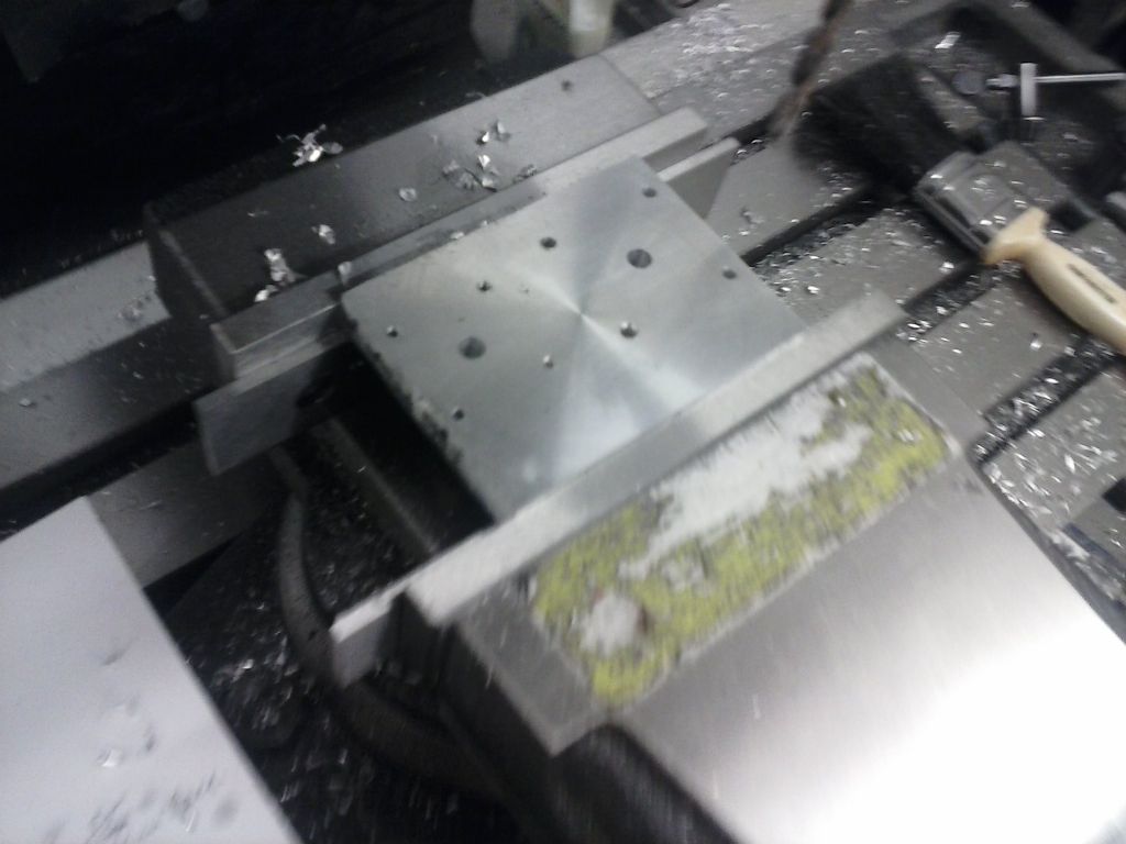
                And happily started drilling and boring.

                Spot the next cockup:

                cam00398.jpg

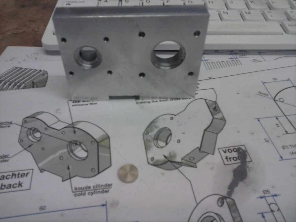
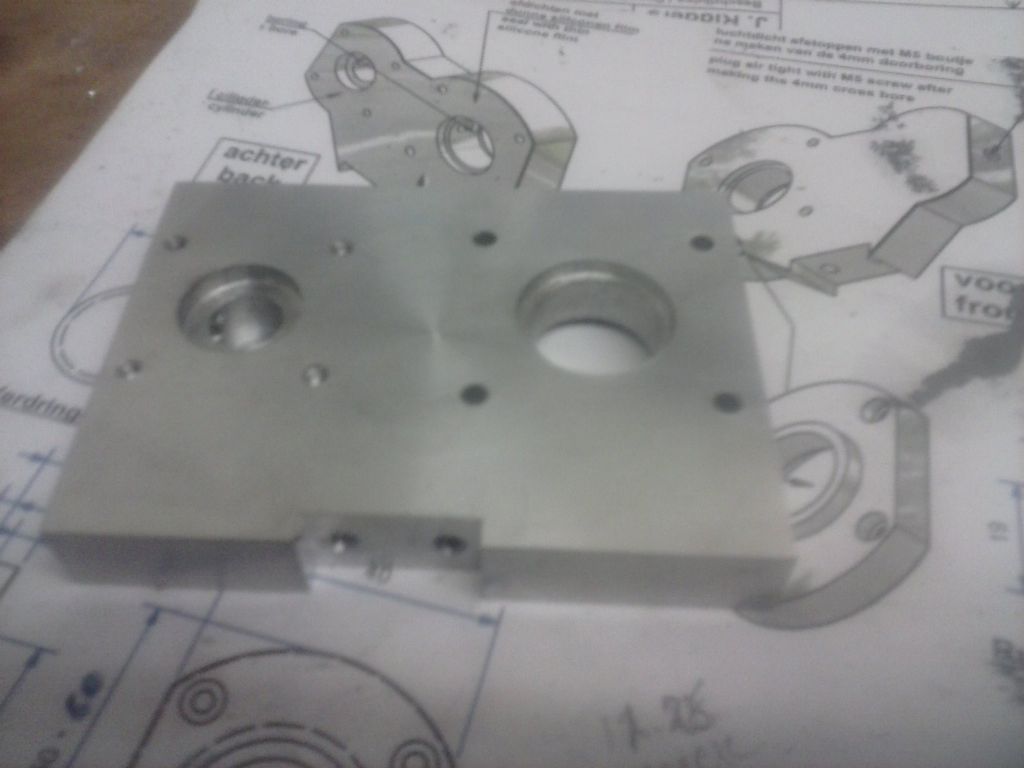
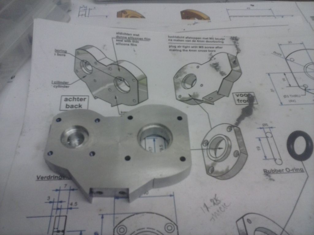
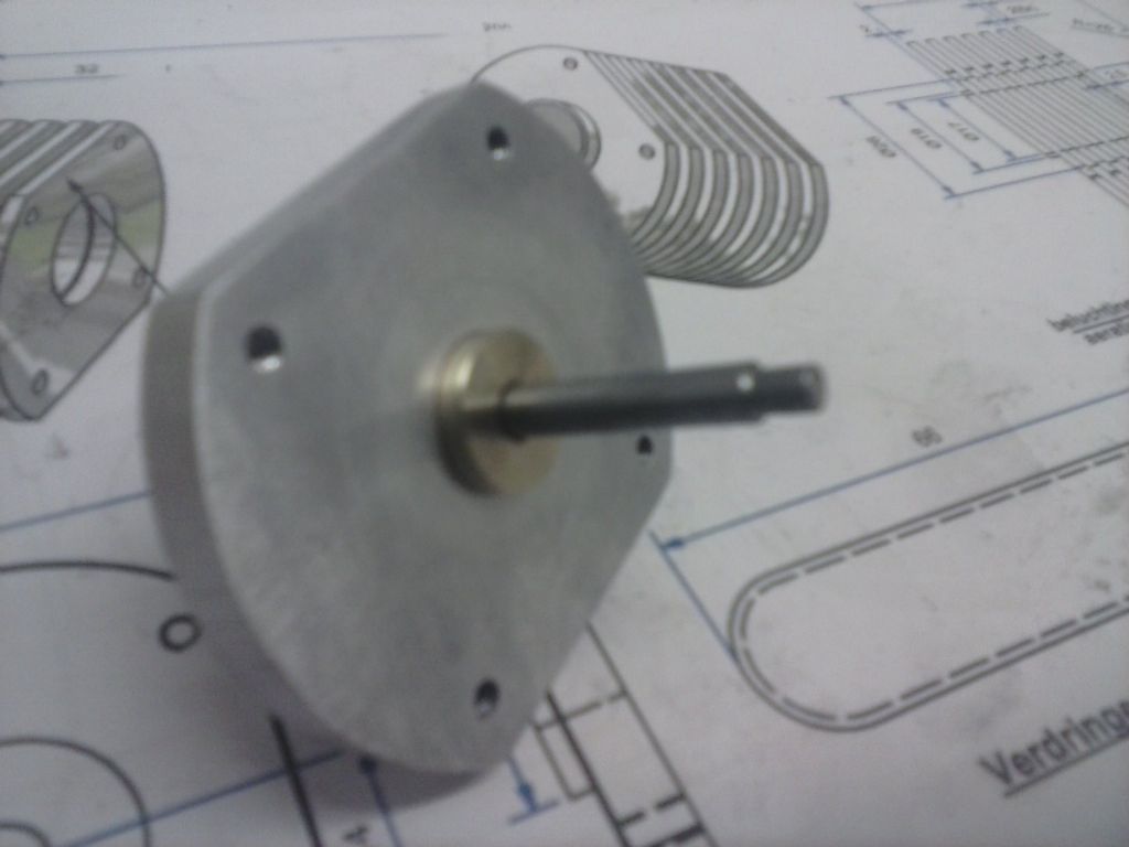
                I had to option of starting again or fixing my error. I elected the latter and decided to make a feature out of it. The power cyclinder holder at the back is drawn to be made out of brass so i figured to fix the mistake the same way. It's actually the first time I've turned brass..lovely stuff to work.

                This is my interference fix:

                cam00399.jpg

                The next stage will have to be making up some filing buttons and axles. No suitable diameter steel bar ins tock so it'll be a plod making them out of hot-roll plate. I'm sure there'll be more cockups along that route too…

                #219084
                pgk pgk
                Participant
                  @pgkpgk17461

                  I can see this thread gets some views. I'm guessing mostly folk shaking their heads in dismay at quite how much trouble I can cause myself and how much of a mess I can make….

                  I spotted the other error on that last pic and made yet another blank up and actually got to the last pic stage without any more faux pas. it's been a long slow slog from there still.

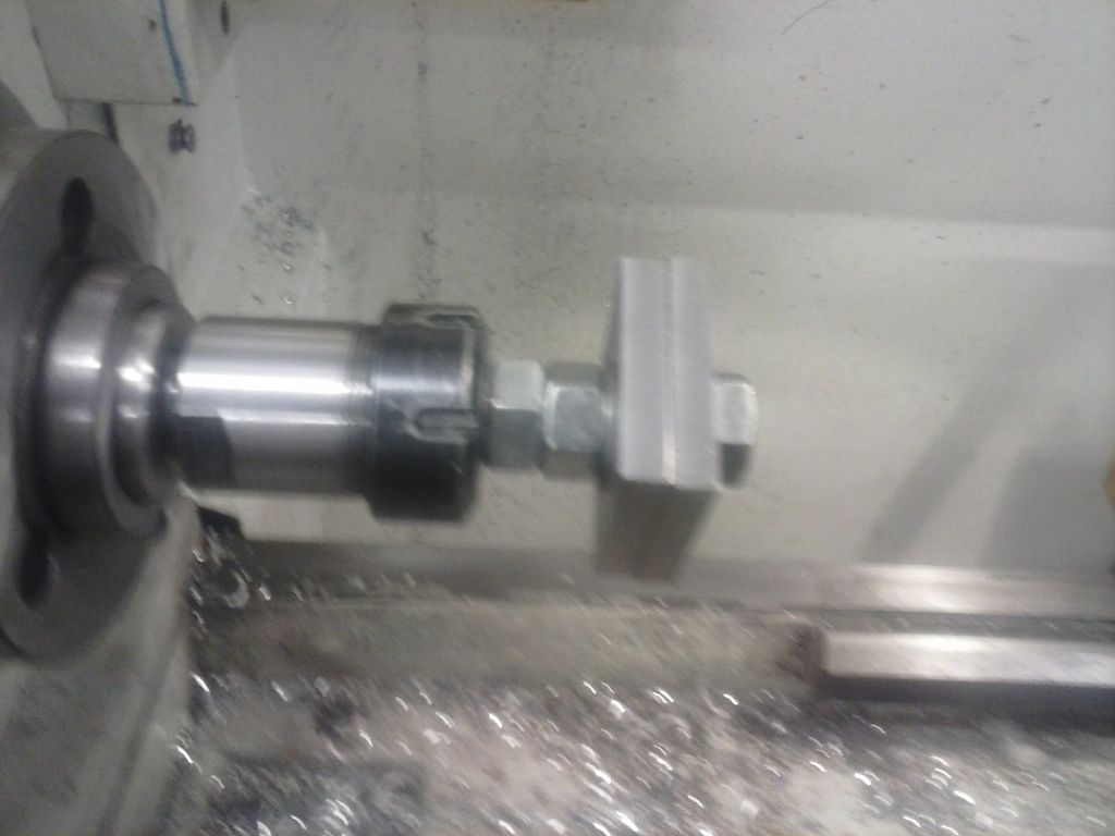
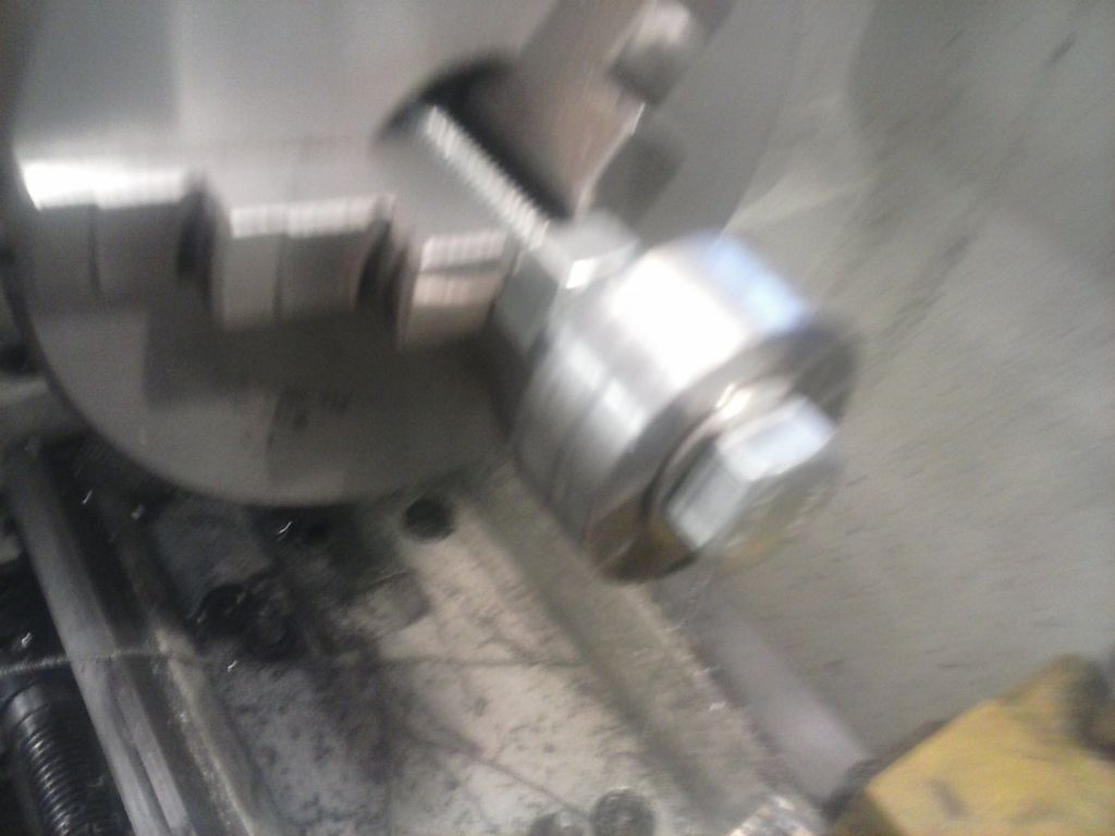
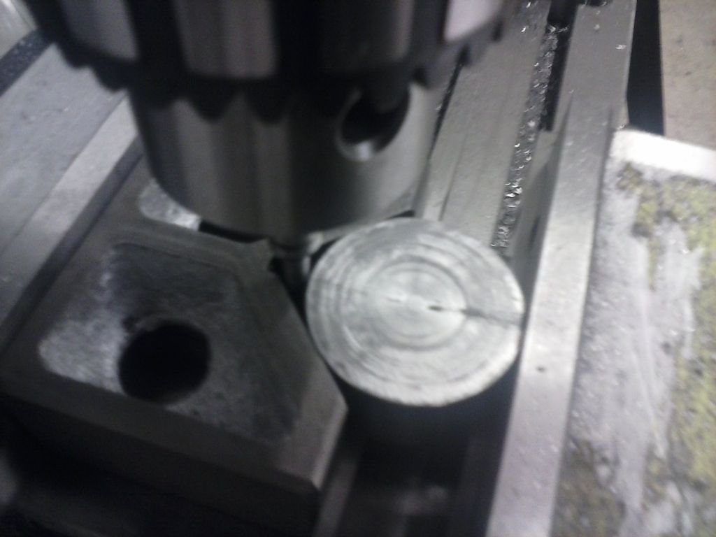
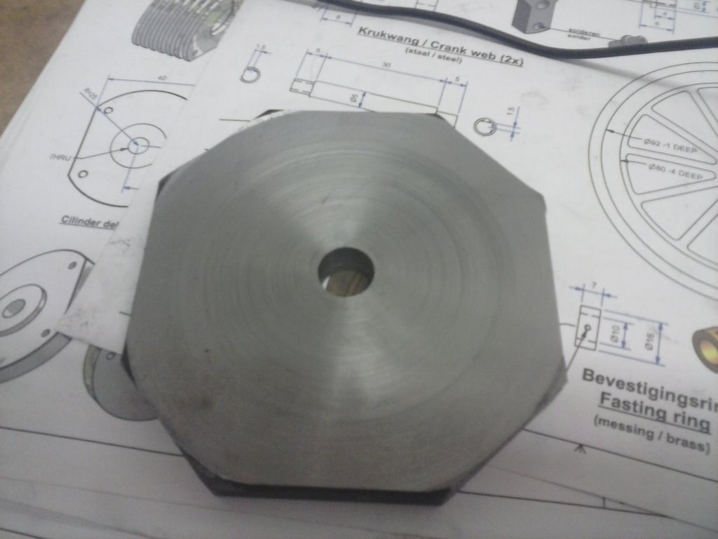
                  I cut and cleaned up the millscale and squared up some 12mm hot roll plate on the mill before drilling a 16mm hole in the middle and mounting it on an M16 bolt to turn the diameter in the lathe.

                  that wasn't so easy either. I'd stupidly expected that I'd be able to knock the corners of easily enough and easier than converting my bandsaw to vertical use (the clamp on it wouldn't hold a small piece like this for cutting off corners). Since It was going to be held by the m16 threads I decided a collet would be the best holder in the lathe. But the crusader lather short taper and the rattling of cutter on corners just kept loosening stuff. So it ended up in the 3-jaw.

                  It was still a slog using an HSS lathe tool to knock this roughly round then finishing with an indexable tool and slow feed to final size.

                  cam00400.jpg

                  cam00401.jpg

                  cam00403.jpg

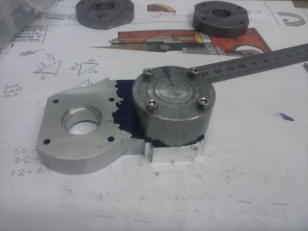
                  Then it was over to the mill to pop a couple of flats on the circles and drill for bolts through that main holder part which I blued and marked up.

                  cam00404.jpg

                  cam00405.jpg

                  It then got roughed on the mill and finished by hand filing with those discs as guides. I'm a filing tyro and not good at it.. took me a lot of patience since I really didn't want to start again (yet again)

                  cam00406.jpg

                  Actually not bad but while you can't see it here I proved to myself yet again that i need a z axis DRO.. the handwheel marks just aren't consistent (and yet i allowed for backlash etc). The two flats are not identical even with touch-offs and care to the same cut depth each side.

                  I had intended to cut the discs down for the second part but decided to keep them for possible mods on this first side if i have to file a little smaller.

                  So a second disc was made up.. much thicker since this would only be one-sided on the part and i know how easily my filing can wander off the horizontal.

                  I also decided not to put flats on which made finding the center on the mill interesting – it's a bit tight in there.

                  cam00408.jpg

                  So the part was blued again for this side and with the disc mounted then once again marked out and milled roughly before filing.

                  cam00409.jpg

                  cam00410.jpg

                  cam00411.jpg

                  I really do hope i don't have to make another one of these – there's a lot of hours in it.
                  #219146
                  Ian S C
                  Participant
                    @iansc

                    Your doing ok, I'v built 18 hot air engines (working ones), but I'v made enough parts for twice that number at least, sometimes I find that the bit that got discarded from one motor, ends up on another. Keep up the good work.

                    Ian S C

                    #219180
                    Bodger Brian
                    Participant
                      @bodgerbrian
                      Posted by pgk pgk on 30/11/2015 19:02:52:

                      It's a pain to retram..can take hours 'cos as you dog the bolts the tram moves.. so that's the next job.

                      Sorry to interrupt the flow of this thread but can I ask what retramming means? I assume the word 'dog' means to grip – am I correct?

                      The subsequent posting re. adjusters didn't really help my understanding

                      Brian

                      #219185
                      Gray62
                      Participant
                        @gray62
                        Posted by Bodger Brian on 03/01/2016 14:21:17:

                        Posted by pgk pgk on 30/11/2015 19:02:52:

                        It's a pain to retram..can take hours 'cos as you dog the bolts the tram moves.. so that's the next job.

                        Sorry to interrupt the flow of this thread but can I ask what retramming means? I assume the word 'dog' means to grip – am I correct?

                        The subsequent posting re. adjusters didn't really help my understanding

                        Brian

                        Brian, Tramming is the process by which the mill head is adjusted to place the mill spindle in perpendicular alignment with the mill table. i.e. the spindle is as near perfect 90 degrees to the table as possible.

                        Some mills (like bridgeports for example) can be a pain to set perfectly, as there are four locking bolts for the head adjustment and as each is tightened, it can move the head a miniscule amount out of alignment, There are twin gauges like these which are designed to aid setting up a mill head.

                        #219186
                        Bodger Brian
                        Participant
                          @bodgerbrian
                          Posted by Graeme W on 03/01/2016 15:13:02:

                          Brian, Tramming is the process by which the mill head is adjusted to place the mill spindle in perpendicular alignment with the mill table. i.e. the spindle is as near perfect 90 degrees to the table as possible.

                          Some mills (like bridgeports for example) can be a pain to set perfectly, as there are four locking bolts for the head adjustment and as each is tightened, it can move the head a miniscule amount out of alignment, There are twin gauges like these which are designed to aid setting up a mill head.

                          Thank you Graeme. I assumed it was something like that but couldn't quite picture which axis was being adjusted.

                          Brian

                          #219379
                          pgk pgk
                          Participant
                            @pgkpgk17461

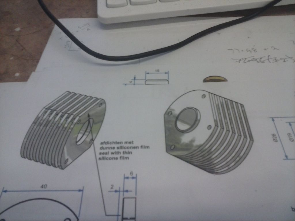
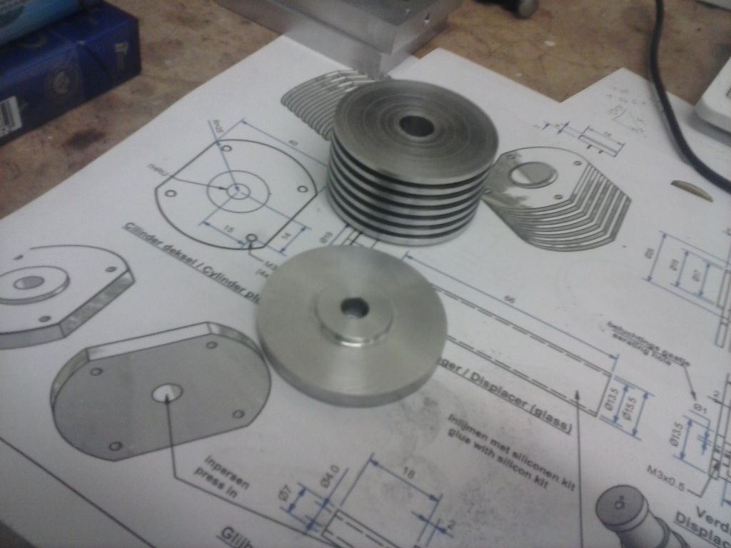
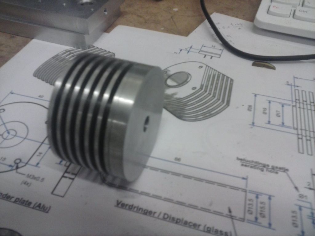
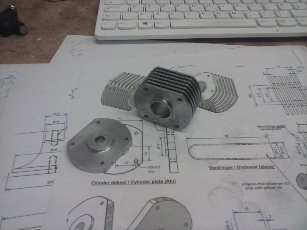
                            the finned cooling cylinder is the part I was wanting to make from the start and disciplined myself not to…it should look shiney and busy.

                            cam00412.jpg

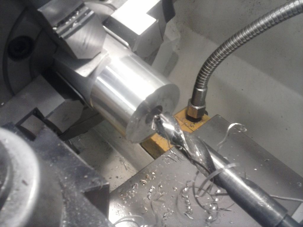
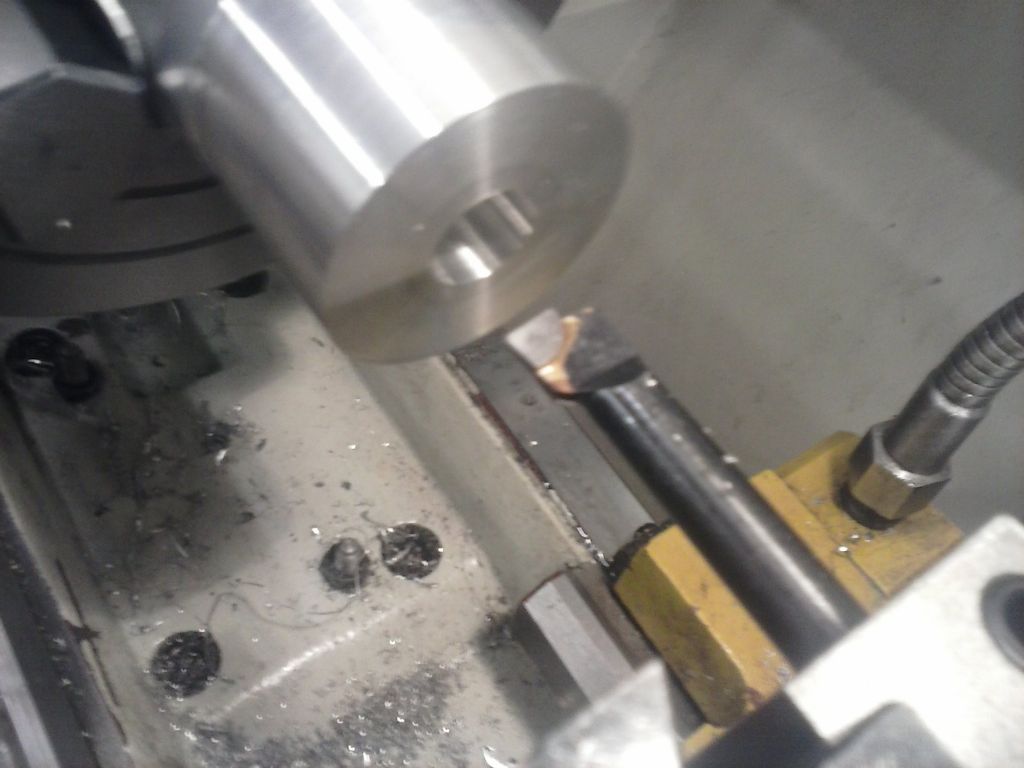
                            Because it's going to need operating on from both ends I used the 4-jaw with some ally slips to prevent marking. Chucked and indicated and turning to diameter was straightforward as was drilling the hole for boring to size. Once again i used one of the boring heads from my mills boring tower and I must be learning something 'cos the telescopic gauge read consistently and to the right numbers.

                            cam00413.jpg

                            cam00414.jpg

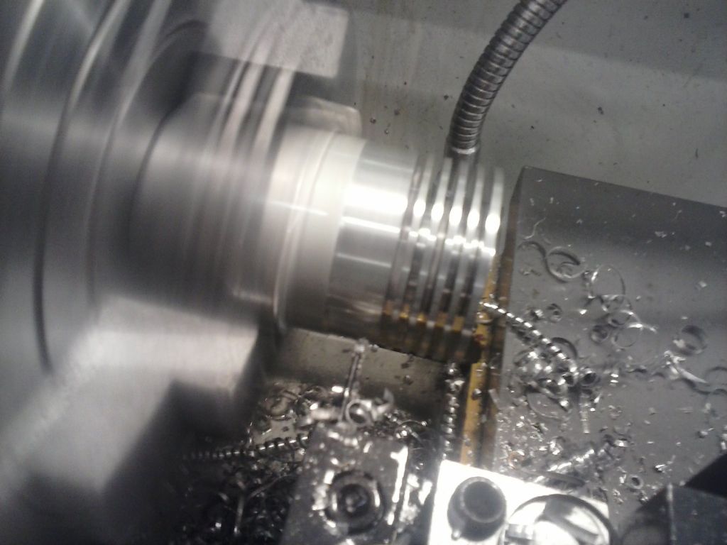
                            Cutting the fins wasn't too bad either. I'd bought a 2mm wide indexable tool and despite some concerns from reading on here how folk get ally sticking to tools it went well albeit every few mm I doused the slot in faux wd40.

                            cam00415.jpg

                            After parting that off I realised that i should make the cylinder cover before flipping the cylinder since the bar was already indexed and sized – so i did.

                            cam00416.jpg

                            Flipping the cylinder and indicating was just a chore. I've done it quicker. But the copunterbore end was done one again using a mill tower boring head as my lathe tool.

                            It's my finish time now but these two parts still need drilling for their bolts and the flats milling on the side. I think I'll drill and bolt them together for the milling and with the benefit of hindsight I should have made and stacked the hot air cylinder holder all together with these two – but too late now.

                            I'm still wondering where the cockup is going to come from…

                            cam00417.jpg

                            #219897
                            pgk pgk
                            Participant
                              @pgkpgk17461

                              I finished up the cold cylinder and it's cap with the flats and holes. No issues and I always work from the centre of the part with DRO for the hole placement so if the sides are out it wouldn't matter. This time it all matches up.

                              cam00418.jpg

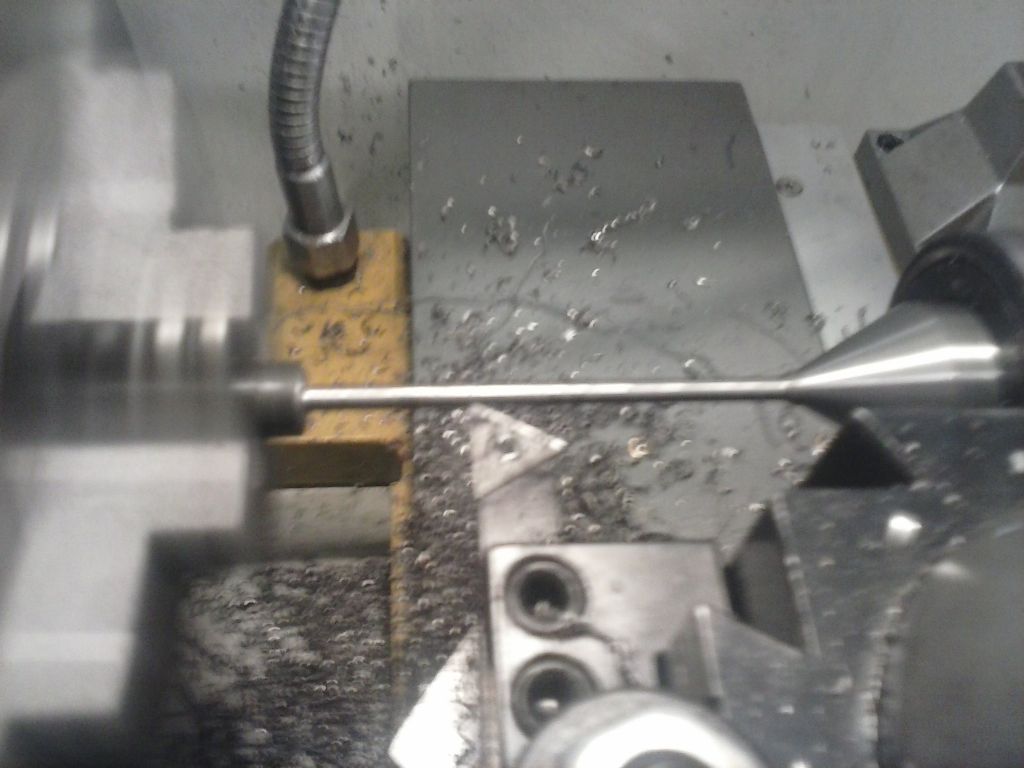
                              Next was the displacer slide bearing and rod. The rod is 4mm diameter and I had no small diameter steel but lots of hot roll from my scrappy mate..so it was the hard way from some 1/2 in:

                              cam00419.jpg

                              The PB bearing material arrived..as well as my new set of cheapo chinky reamers. Annoyingly the first attempt was bang on dimensions until I bored it and as expected that stretched the press-fit diameter. Instead of touching off and skimming from that mark i used the earlier DRO numbers..and went undersize- DOH!

                              The second one came out right but the i spent some time polishing my DIY 4mm rod to a very good fit. I'd made it spot on 4mm and needed to lose 0.03mm before it slid nicely. Perhaps the reamer cuts a tad undersize?

                              Next annoyance was that my set of cheap taps and dies (I've owned for years) and never used the m3 die.. only has an m3 x0.6.. so I have to buy a correct one. The rod ends are turned to 3mm and sitting in the project box.

                              cam00421.jpg

                              Which means a decision on what to do next. I have some brass and ally on order for further parts and it's probably time to think about the fly wheel and baseboard so that rods can be made to size.

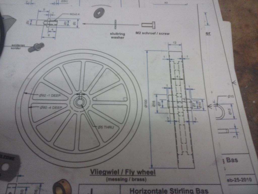
                              The flywheel calls for a piece of brass 100mm diameter and 20mm thick and complex cutting /filing without a rotary table. I'm not confident of making that in one attempt and at some £25 for a chunk of brass i really don't want to screw up. I'm currently thinking of using steel with a brass press-fit boss but would appreciate thoughts and thoughts about the order of working this….volume/mass of brass and steel are close enough that if the wheel weight actually matters then the substitution won't…

                              cam00422.jpg

                              #220002
                              Ian S C
                              Participant
                                @iansc

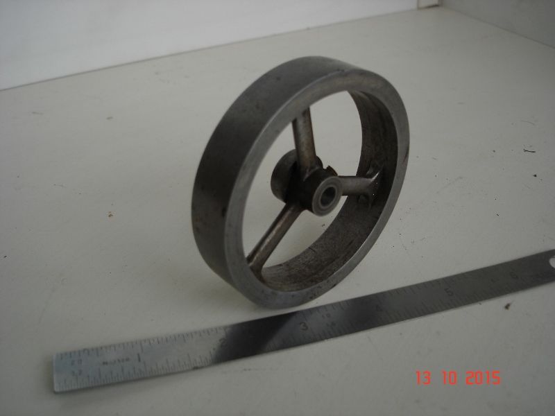
                                Too many spokes, well that's my view of it, some of my smaller flywheels have only 3 spokes, made one up the other day for a Stirling Engine in a boat, I needed a heavier FW than was in use, but needed to eliminate excess weight, so that 3" FW has 3 spokes 6 mm x 3 mm.

                                Just because the plan shows one pattern for a part doesn't mean that must be used,.

                                Ian S Cdsc01132 (800x600).jpg

                                #220123
                                pgk pgk
                                Participant
                                  @pgkpgk17461

                                  I appreciate the comment, Ian, but this is more about following the drawing than just making an engine… solving the problems of how to do it.

                                  The easiest flywheel would probably be just to thin the spoke area from the 4mm shown to, say, 2.5/3mm and drill a series of large radial holes.

                                  #220221
                                  Ian S C
                                  Participant
                                    @iansc

                                    Been there, and done that too, and used the fly wheel/hand wheel from an old sewing machine.

                                    Ian S C ps., that 3 spoke FW started as one of a pair on a solenoid motor that I built before my hot air engines started to be my model of choice.

                                    Ian S C

                                    #220476
                                    pgk pgk
                                    Participant
                                      @pgkpgk17461

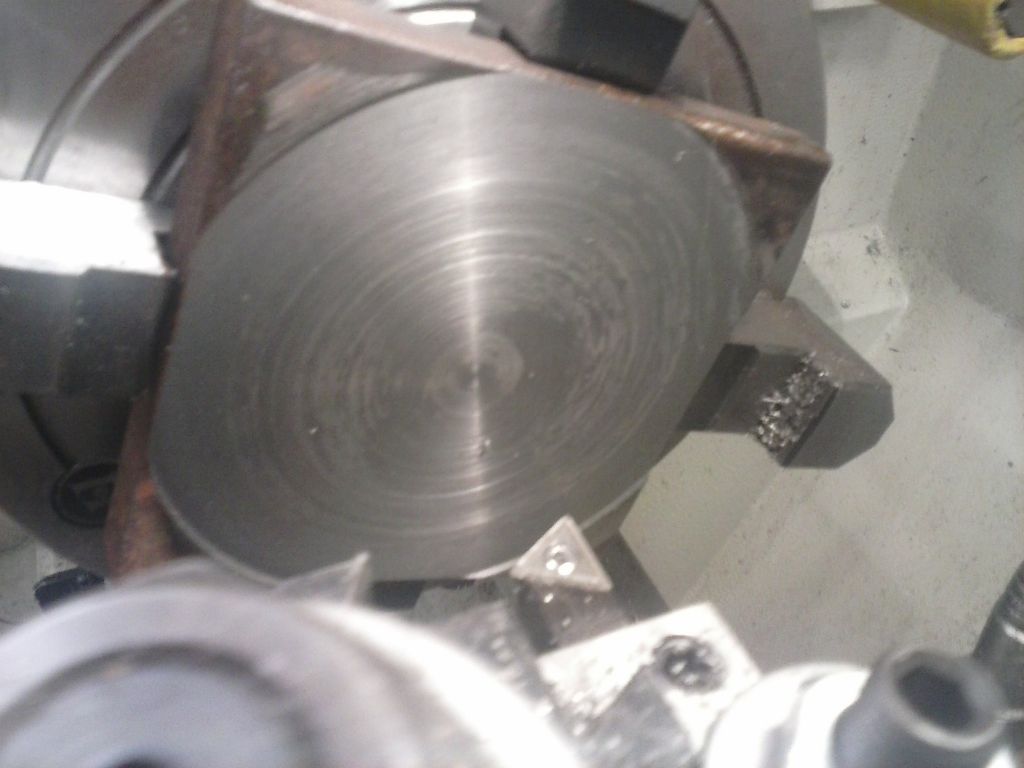
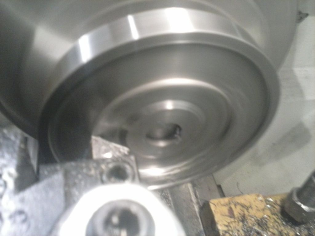
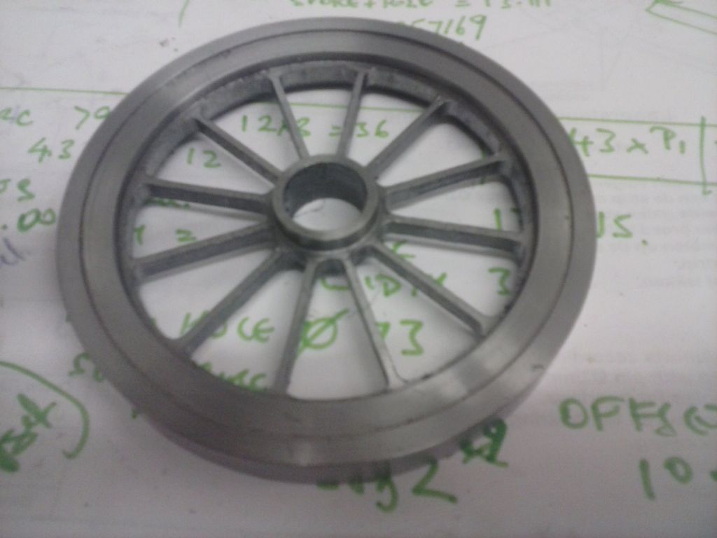
                                      It's taken me some hours to turn a chunk of 15mm hot-roll into a flywheel blank. Firstly in the 4-jaw using HSS to skim off the scale then cut off the corners to an octagon after boring a centre hole.

                                      cam00424.jpg

                                      cam00425.jpg

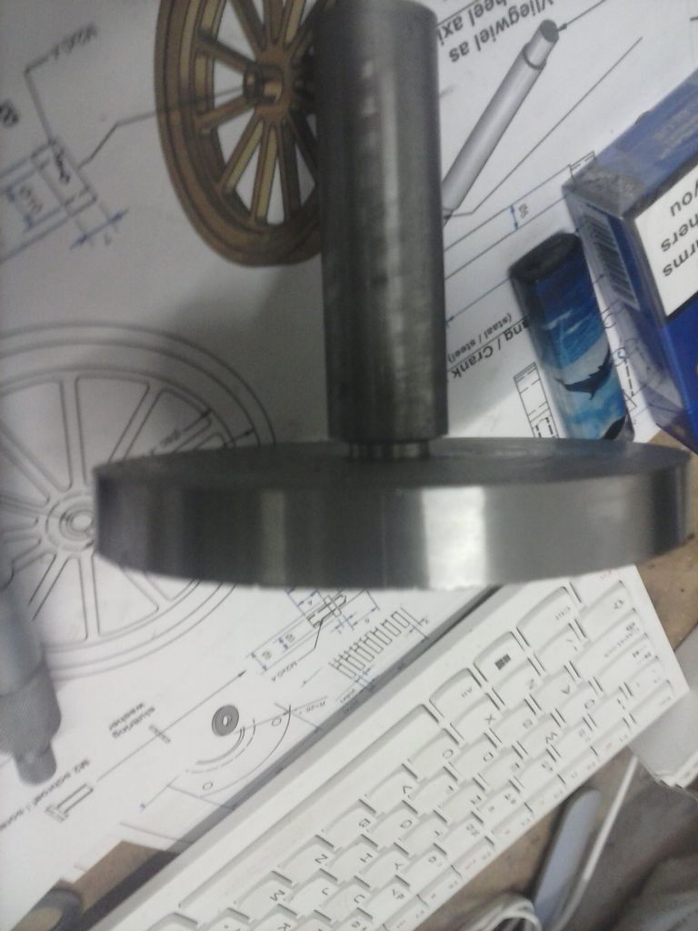
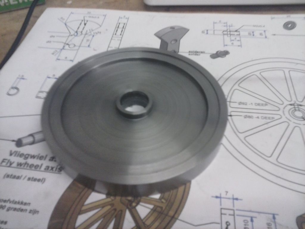
                                      This allowed me to make up an interference fit mandrel to hold the thing for knocking the corners off with more HSS before facing cleanly with indexable tooling , turning to diameter and thinning the spoke web.

                                      One problem was that with only 12mm final hub thickness it's difficult to get that running true when swapping the mandrel to the opposite side although the tool pressure itself did help to straighten it up and the end result wobble is hardly noticeable below 280 rpm on the lathe so at this engine speed i guess it'll be hidden?

                                      With the benefit of hindsight (learning curve) perhaps i should have had a bigger diameter mandrel bar for a larger shoulder for it to seat against?

                                      The rim turned to a mirror finish using one of those lathe tools that uses the 'unused' angles of a diamond shape insert. the spoke web area was turned with a triangular insert as a knife tool angle for both the outward and inward cuts. the finish there does show some circular lines due to the small tip radius. Hopefully I can sand those off the finished item.

                                      cam00426.jpg

                                      cam00427.jpg

                                      cam00429.jpg

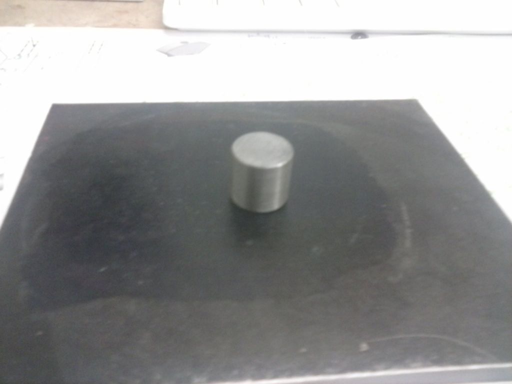
                                      the game plan is a brass press-fit insert for the middle.

                                      My issue now is how best to cut this for the spokes without a rotary table or scroll saw.

                                      I see two options.. either do the math for a huge series of chain drilled 3mm holes(DRO bolt circles) and then some bigger ones towards the circumference to get a junior hacksaw blade in there then lots of filing Or stick to a 3mm hole in each spoke gap corner and then whittle away with 3mm endmills. I have found (to my suprise) that i own 4 4-flute 3mm endmills but only one 2-flute so it'd be a lot of plunge cutting OR a series of 4mm+ chained holes after the 3mm corner piercings and tidy up with the endmills on the radii and hand file inside the rim. Unless you guys have a better idea??

                                      #220482
                                      Michael Gilligan
                                      Participant
                                        @michaelgilligan61133
                                        Posted by pgk pgk on 10/01/2016 21:47:56:

                                        My issue now is how best to cut this for the spokes without a rotary table or scroll saw.

                                        I see two options.. either do the math for a huge series of chain drilled 3mm holes(DRO bolt circles) and then some bigger ones towards the circumference to get a junior hacksaw blade in there then lots of filing Or stick to a 3mm hole in each spoke gap corner and then whittle away with 3mm endmills. I have found (to my suprise) that i own 4 4-flute 3mm endmills but only one 2-flute so it'd be a lot of plunge cutting OR a series of 4mm+ chained holes after the 3mm corner piercings and tidy up with the endmills on the radii and hand file inside the rim. Unless you guys have a better idea??

                                        .

                                        I offer this as 'food for thought' [i.e. work out the details for yourself] …

                                        What you have made so far is already an approximation of a Rotary Table: All you need is a bearing-post, a stop-pin or two, and some clamps. … So, draw what you want and carefully plan how to cut one segment.

                                        Cut the first side of a spoke on the mill, then index it round so that the next one can be cut using exactly the same tool path [and so on] … When you have completed that, flip the wheel over, to cut the other side of each spoke in the same way. At worst, you would then cut to complete the triangles, and only need to file the curve. At best You may even be able to finish-cut the curve by hand rotation of the wheel [But please take care!]

                                        I hope that makes sense … it's been a wearisome day & I'm off to bed.

                                        MichaelG.

                                        #220507
                                        pgk pgk
                                        Participant
                                          @pgkpgk17461

                                          I had something like that in mind when I referred to whittling away at the spokes with endmills. I have various jig ideas in mind but still see more pitfalls than promise in them..

                                          #220510
                                          Michael Gilligan
                                          Participant
                                            @michaelgilligan61133
                                            Posted by pgk pgk on 11/01/2016 07:34:02:

                                            I had something like that in mind when I referred to whittling away at the spokes with endmills.

                                            .

                                            Oh

                                            #220556
                                            Ian S C
                                            Participant
                                              @iansc

                                              I tend to drill the corners of each space with the correct size drill for the radius required, then use either 1/4" or 3/16" drills to chain drill, the spokes are then finished with files, I think the only one that I milled was a 14" FW for an IC engine.

                                              Ian S C

                                              #220580
                                              steamdave
                                              Participant
                                                @steamdave

                                                It's a bit late to cure your runout problem with this flywheel but for the future, there is a very simple tool you can make using a bit of scrap steel bar and a couple of ball bearings from a computer hard drive.

                                                Have a look at

                                                https://www.youtube.com/watch?v=tn7A9PqNftY which was probably the first to show the wider audience this simple trick and Gadgetbuilder's tidied up version
                                                http://www.gadgetbuilder.com/CenterFinder.html#BumpCtr

                                                Dave
                                                The Emerald Isle

                                                #220587
                                                pgk pgk
                                                Participant
                                                  @pgkpgk17461

                                                  ..one of those things i remembered after the event. It might just get used still if I end up marring the surfaces while filing in the vice. It'd probably only take a fraction of a mm to skim parallel an i have yet to pressfit the central brass and machine that.

                                                  #220851
                                                  pgk pgk
                                                  Participant
                                                    @pgkpgk17461

                                                    Oh, bother (although the wording used was a tad more resigned)..

                                                    I built a jig for drilling milling the spokes..simple enough and pics later. One of my fears materialised when I snapped a centre drill with the point wedged in the job at a critical position. I then risked and destroyed a cobalt drill on it before recalcuating and trying to drill more radially and pick out the fragment sideways…misjudged the distance needed and destroyed a slightly bigger cobalt drill. After the event i have read up on assorted ideas re getting such broken centre drill tips out but my best and only remaining option is to flip and relocate the part, drill from the back and punch it out.

                                                    At least with my jig I have a chance of relocating it If it ends up too messy then I'll just bite my lip and make another glad that it wasn't an expensive chunk of brass.

                                                    #221381
                                                    pgk pgk
                                                    Participant
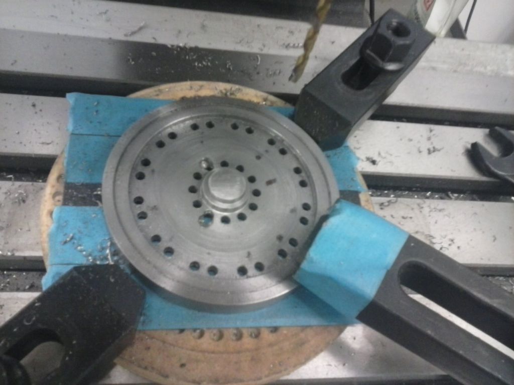
                                                      @pgkpgk17461

                                                      The jig was simple enough with a central boss that gave a nice smooth fit. Just a piece of hot roll plate and an insert screwed m8.

                                                      cam00430.jpg

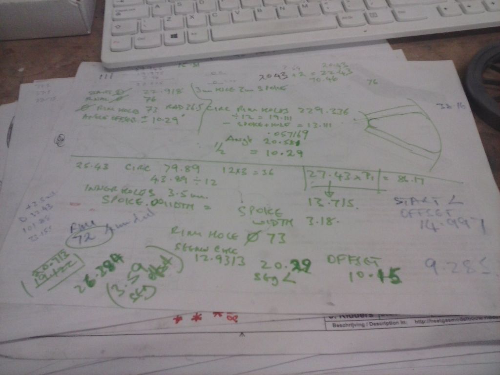
                                                      My usual scrawled math once I'd dragged out my school memory and had an epiphany..

                                                      cam00436.jpg

                                                      As reported above I snapped a centre drill and left the tip wedged in. Fortunately I had enough holes to use for a reasonable relocation after flipping the part and drilling it out from the back. But i did lose some quality of indexing.

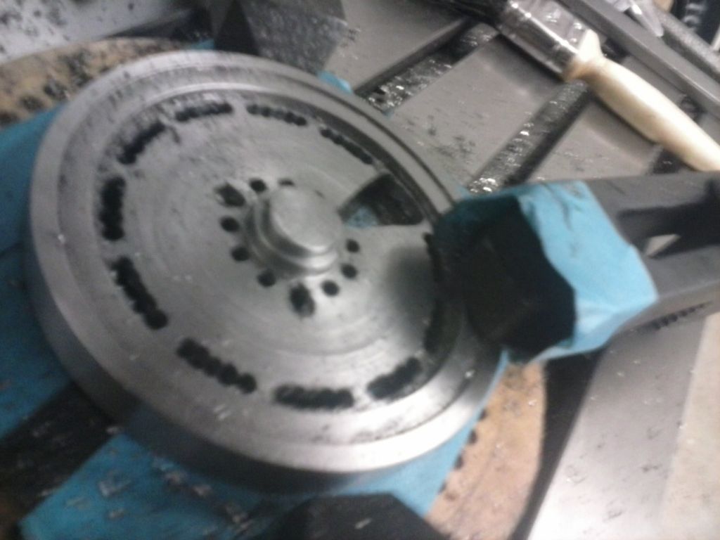
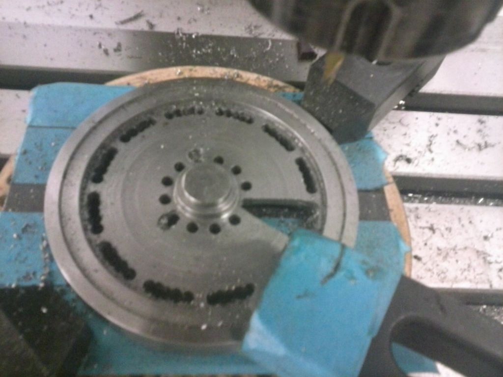
                                                      This then became the expected chain drilling.Once again I found I couldn't get a nice gap on the holes without drills moving so ended up using a 2-flute endmill to join up

                                                      cam00431.jpg

                                                      cam00432.jpg

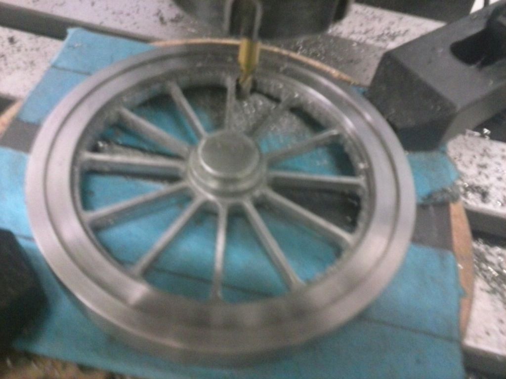
                                                      Getting each segment out was more math to decide on offsets and milling numbers…and a slow plod. This was where i made my next error by trenching too deep and even with a 2-flute getting some gouging into the residual spoke material.

                                                      cam00433.jpg

                                                      cam00434.jpg

                                                      The only fix i had for that was to make the spokes thinner than the drawing. There's still a slight ding visible but i couldn't thin the spokes more and evenly to hide it. Again a learning thing…leave more room next time and then edge up to the mark…

                                                      Finally i decided to try and mill the spoke rim edge turning the flywheel by hand. Yes i was VERY careful and took just 0.1mm slivers to nibble away. What i did learn was quite how much thumb pressure it takes to hold against a 4mm endmill and how much more pressure it takes conventional compared to climb milling and how climb milling tries to pull itself along…

                                                      cam00435.jpg

                                                      There's still some filing and sanding to go…and the central boss to make. More scary that there's probably 20 hrs work in that wheel although i reckon i could knock 75% off that if I had to make another. I'd figured most of the shortcuts out too late.

                                                    Viewing 25 posts - 26 through 50 (of 112 total)
                                                    • Please log in to reply to this topic. Registering is free and easy using the links on the menu at the top of this page.

                                                    Advert

                                                    Latest Replies

                                                    Home Forums Stationary engines Topics

                                                    Viewing 25 topics - 1 through 25 (of 25 total)
                                                    Viewing 25 topics - 1 through 25 (of 25 total)

                                                    View full reply list.

                                                    Advert

                                                    Newsletter Sign-up