Jan Ridders Coffee Cup Stirling

Advert

Jan Ridders Coffee Cup Stirling

Home Forums Beginners questions Jan Ridders Coffee Cup Stirling

Viewing 25 posts - 1 through 25 (of 132 total)
  • Author
    Posts
  • #227916
    SillyOldDuffer
    Moderator
      @sillyoldduffer

      Having built Jan Ridders Coffee Pot engine I am, surprise surprise, unable to get it to run.

      There are no leaks and the engine spins freely. The piston passes the 'pop' and vacuum tests. That's the good news and I'm now focussing on the various defects. Of these I'm particularly suspicious of my displacer for two reasons but lack the experience to know if I'm right to worry or not.

      Firstly the sheet of polystyrene carefully put aside to make the displacer has gone AWOL and I temporarily used cardboard instead. Is cardboard suitable for this purpose? (Cardboard doesn't feature as displacer material in any of the designs I've seen.)

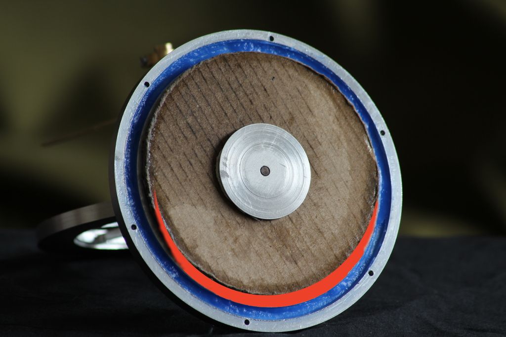
      Secondly, due to a cock-up making the upper plate, the displacer is smaller than it should be. The glide-bearing hole in the upper plate is off-centre and the diameter of the displacer is reduced to stop it fouling the cylinder wall. The effect is highlighted in red in the photo. How critical is the size of the displacer relative to the size of the cylinder?

      displacer.jpg

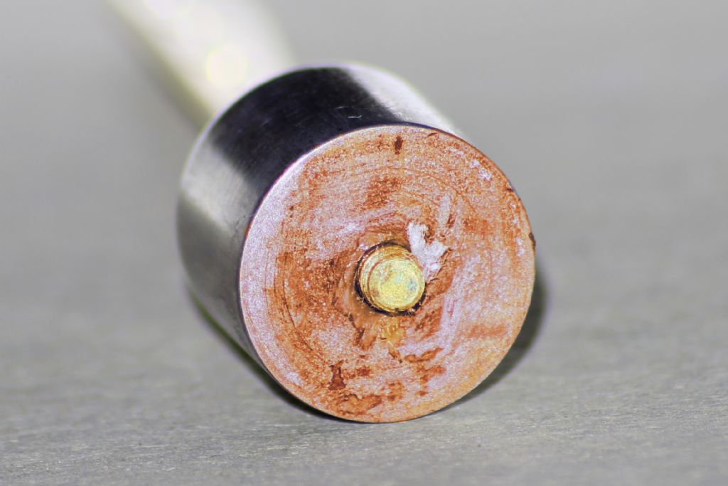
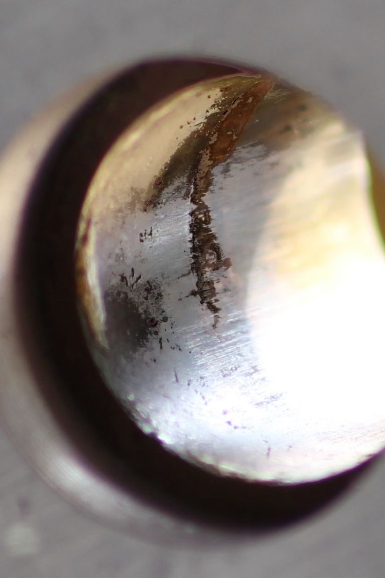
      It's not the cause of my problems but other builders of this engine might be interested in the second picture. It shows corrosion of the steel piston caused by acetic acid from the RTV I used to seal the displacer-cylinder. The corrosion is worse than the picture implies and it also greened up the exposed brass-work.

      piston.jpg

      As usual I will be very grateful for all help and comments.

      Regards,
      Dave

      Advert
      #8030
      SillyOldDuffer
      Moderator
        @sillyoldduffer
        #227917
        Peter Krogh
        Participant
          @peterkrogh76576

          Hello Dave,

          I can't comment on the displacer, but I can say that the type of RTV used in fish aquariums doesn't give off the acid and won't rust/corrode things.

          Pete

          #227923
          SillyOldDuffer
          Moderator
            @sillyoldduffer

            Thanks Peter,

            I used "Pro Seal Blue RTV Silicone Instant Gasket".

            It might be past it's best as I've had the tube in my garage for several years. Took a few days to set as well as smelling strongly of vinegar. The seal is good though so I'm not too unhappy.

            As the blue colour of the sealant doesn't improve the look of the engine I may visit the fish section of my nearby garden centre for a replacement.

            Dave

            #227932
            Gordon W
            Participant
              @gordonw

              The displacer should have a clearance inside the cylinder, how much is debatable, but I would say 1mm in a 100mm should work. The depth of the displacer is relevant also, on your's it looks thin, also c/board corries will pass air. Can't see why board would not work but will need some engineering to stiffen up.

              #227968
              SillyOldDuffer
              Moderator
                @sillyoldduffer

                Many thanks Gordon.

                My effective displacer gap is much bigger than 1mm in 100mm so that definitely needs fixing.

                You are right that my displacer is thin: the cat food carton cardboard I used is only 1.8mm thick. I didn't realise that the depth mattered which may have been unwise given that the design calls for 4mm.

                As it's easy to do I'll double the thickness and cut the displacer for a much closer fit. While I'm at it I'll seal the corrugations as well – airflow through them may be reducing the effective thickness of the displacer even more. Oh dear.

                Fingers crossed!

                Ta,

                Dave

                #227976
                Peter Krogh
                Participant
                  @peterkrogh76576

                  Keep posting, Dave. I'll be following the same trail later this summer!

                  Pete

                  #227981
                  Howi
                  Participant
                    @howi

                    Thicker cardboard will help, you say it spins freely, how many revs or seconds?, my ltd striking has a removable plug , with the plug removed it will spin over very freely  and for quite a while, put the plug back in and it does not spin for anything like the same time (air resistance slowing things down in sealed system).

                    What about timing, it should only run in one direction though that can be reversed by moving timing 180 deg.

                    How did you check for leaks? An air leak is a real killer.

                    Also look up regenerators, they do improve performance, but obviously get it going first.

                    Edited By Howi on 02/03/2016 17:33:01

                    #227985
                    Ajohnw
                    Participant
                      @ajohnw51620

                      The plan sizes are a 94mm dia x 4mm thick displacer in a 96mm bore piece of plastic tube. Displacer in balsa or polystyrene. The metal flanges on the displacer should be 1mm thick in aluminium. All hardly any weight at all.

                      It;s a low temperature engine so it wont be happy with increases in weight especially on the displacer.

                      I suspect that the silicone rubber tube for sealing he mentions might be the kind that is pushed over bare wire to insulate it but the green one used on the earth in mains wiring is probably over 2mm dia.

                      John

                      Edited By Ajohnw on 02/03/2016 17:57:56

                      #227992
                      Ajohnw
                      Participant
                        @ajohnw51620

                        Ebay 26100958875 should be ok for the tubing. They do several sizes.

                        John

                        #228003
                        SillyOldDuffer
                        Moderator
                          @sillyoldduffer

                          Progress Report

                          I've fitted a double thickness (4mm) cardboard displacer with edges sealed with a smear of latex glue. Still not running in either direction. (Until Howi's advice I'd only tried spinning it clockwise.)

                          Some more facts:

                          I followed Jan's design fairly closely. My acrylic tube is 96mm inside diameter. The other components are to spec except that the upper and lower plates are 1/4" (6.25mm) thick rather than 5mm. The flywheel is 1/4" thick rather than 7mm and I increased the diameter to 106mm to compensate. (Design says 100mm diameter.) The piston is mild steel rather than graphite but that's allowed. I used RTV silicone instant gasket rather than cut rubber hose to make the seals. The plate fixing spacers are drilled through and secured with 2mm stainless nuts and bolts rather than being tapped M2 at the ends with an air gap between.

                          The various bearing points have been de-burred. The engine was spun by hand and then given about 30 minutes drive with an electric meccano motor for "Running In – Please Pass"

                          Mistakes:

                          Due to a measuring boob the lower plate groove is 7mm wide rather than 4mm. The extra width is inside the cylinder and the dead space is partly filled with RTV.

                          As previously confessed the hole in the upper plate for the glide bearing is not centred exactly. The new displacer runs closer to the cylinder wall but it must be a tad unbalanced as a result.

                          The flywheel wobbles slightly and needs to be shimmed. I'm not entirely happy that it's balanced properly.

                          Tests

                          From a flick the engine spins 9 to 11 times with the power piston disconnected. It spins 6 – 7 times when connected. Providing heat doesn't give more revolutions.

                          The upper and lower plate seals where tested by immersing the engine body in water. The upper plate brass work was tested by spinning with soapy water smeared around the bolts and seams. The displacer piston rod and piston where tested with sewing machine oil, now removed. As I've had the engine apart I will have to repeat the leak tests.

                          Visual check. The displacer doesn't seem to be fouling the side, top or bottom of the cylinder.

                          Feel check. Rotating the engine doesn't reveal any stickiness in the motion.

                          Next step will be to fix the flywheel wobble and recheck the balance. Unless I get more good advice that is!

                          Thanks again,

                          Dave

                          #228014
                          Howi
                          Participant
                            @howi

                            One test you could try apply some hot water to the base (hot) plate, spin the flywheel clockwise, then anticlockwise, one way should spin better/longer than the other. If you do not get this something is badly wrong somewhere, most likely to be air leak, ltd strilings will NOT tolerate air leaks, it needs to be a sealed system to work.

                            How are you checking for air leaks?

                            I used a removeable screw, replaced with an adaptor to connect to some silicon tubing, immerse the whole thing in water and blow into the tube. With it out of the water, blowing and sucking on the tubing should get the piston moving.

                            #228038
                            Ian S C
                            Participant
                              @iansc

                              It would be best if the displacer was concentric, and if you can't get some polystyrene 4 mm thick, maybe 2 thinner bits, you could use balsa wood. You need to cut down the bulk of the metal in the disc in the centre of the displacer, on my 6" dia LTD motor the centre piece is an aluminium nut with a flange about 3/4" dia x .020" thick, the rod is a bit of bike spoke. I wonder if you could glue a bit of aluminium over the out of centre hole, and re-drill the hole in the centre, I would suggest that unless the instructions say other wise the displacer should have a gap of about 2 mm, if its too close it causes drag as the air moves back and forth.

                              Have you added weight to the flywheel to balance it against the weight of the displacer and piston. Test it with the bottom plate removed, Blue Tac is good for temporary weight, the balance has to be fairly good.

                              I,m not that fussed by Jan's idea of using steel for a piston, cast iron would be far better, but if you follow the instructions, the motor should go, but you might have to work through it as Brian and pgk pgk have on their motors.

                              What sort of bearings have you used, the main bearings should be ball races, take the shields of the sides of the bearings, and wash out the grease, don't oil them, that's it.  On my motor there are ball races on the big ends, and they should get the same treatment.

                              Ian S C

                              Edited By Ian S C on 03/03/2016 09:16:30

                              #228042
                              Ajohnw
                              Participant
                                @ajohnw51620

                                I had wondered about other ways of making very low weight displacers. Maybe make a disc of something easy to cut and light. Cut most of the interior away and cover with aluminium foil. I'd been wondering about using foam board but it's only about in one thickness as far as I know,

                                Sadly B&Q etc don't sell polystyrene foam cutters for a couple of quid now. The price is up eg but could be cheaper elsewhere

                                **LINK**

                                They are pretty easy to make – use stainless mig wire. There should be info about on the web. Model aircraft etc people cut wing formers from it.

                                Edit – on the other hand if some one hasn't anything suitable for feeding current into a short length of mig wire they would be better off buying some ni chrome wire. There is lots on ebay these days.

                                John


                                Edited By Ajohnw on 03/03/2016 09:43:51

                                Edited By Ajohnw on 03/03/2016 10:30:45

                                #228044
                                pgk pgk
                                Participant
                                  @pgkpgk17461

                                  If memery serves myfordboy's youtibe channel shows him cutting a polystyrene disc out using a soldering iron with a bit of wire attached to the tip and a very crude but effective jig on a even simpler version of this type engine.

                                  And as i discovered they'll run a lot better in a cool room than a hot one

                                  #228045
                                  Neil Wyatt
                                  Moderator
                                    @neilwyatt

                                    Laminate a few frozen pizza trays?

                                    #228049
                                    Trev67
                                    Participant
                                      @trev67

                                      Hi Dave,

                                      I am by no means an expert, but I have made one of these and it runs. I used available materials for mine, so I have a steel piston, silicone sealant on the top and bottom plates, and the spacers are made stainless, as I didn't have any plastic available. So those factors shouldn't stop it running.

                                      I think your problem is the displacer.

                                      As you have made the displacer piston thinner have you made corresponding adjustments to the length of the piston rod and or the connecting rod to bring the top face of the displacer piston as close as possible to the under side of the top plate at tdc.

                                      Have you made the displacer cylinder length such that the displacer piston almost touches the bottom plate at bdc.

                                      If you have too much dead space, then I think this would stop the engine running.

                                      Other factors that will stop it running:

                                      Air leaks, I tested mine by removing the power piston and sitting the engine in water covering just over the top plate. I sealed a bit of tube into the power cylinder with blu tak and blew down it, any leak is obvious from the bubbles. you don't need much of a leak to stop it working.

                                      It helps if you achieve reasonable balance, I took the bottom plate off, then give it a spin, a bit of blu tak will do to get it fairly close.

                                      Obviously the whole thing needs to be as free running as possible, but it seems like yours is ok, also the power piston needs to be a good fit, but it sounds as if you are happy that yours is ok.

                                      If it were mine I would:

                                      Take the displacer cylinder apart and check how close the diplacer comes to the top plate.

                                      Put the tube on and check how close the underside of the diplacer comes to the bottom plate, obviously making allowance for the groove in the bottom plate.

                                      These measurements need to be pretty small, probably 1mm or less. If not before doing any re engineering, get some better material for the displacer piston, either polystyrene or balsa.

                                      If it is any consolation I was talking to Martin Gregory on the SMEE stand at ME exhibition, and when I told him I'd built one of these Jan Ridders engines and it ran, his comment was that i was the only person he'd come across that had made one work. Apparantly the proportions are not quite right, but I can't quite remember what is wrong. Martins own engine will run on the heat from your hand, the one I made from the Jan Ridders design needs a good cup of boiling water to work. But that aside it definately can be made to work. No disrespect mean to Jan Ridders he has done some great work designing engines and giving them away free.

                                      Hope this helps

                                      Good luck

                                      Trevor

                                      #228050
                                      Gordon W
                                      Participant
                                        @gordonw

                                        Polystyrene should be easy to get, the back of any shop, pub etc. usually have loads to get rid of. I burn it , it's the easiest way. For a one off just use a sharp knife, serrated kitchen knife works. Finish with sandpaper or similar. I mark out leaving 3 or 4 mm on size. Make a hole in center and glue a bit of dowel with wood glue. Clean up to size, then trim dowel and drill for the con. rod. That's just one way of course. balsa wood could be used, or any thing that is light and stiff.

                                        #228058
                                        Ajohnw
                                        Participant
                                          @ajohnw51620

                                          Jan Ridders does have plans for a run on the hand model but it needs a temp difference of more than 10C to run like that which is somewhat dependent on the weather.

                                          This model is a little different. It's intended to have a model aeroplane prop mounted on it. I'd suggest one with a low pitch.

                                          From looking at a number of designs I don't think that JR's engines of this type are any different to others really. I'd say the main difference is the weight of components that have to move when the engine is running especially the ones claimed to run at very low temperature differences.

                                          They are curious things. There is some rocket science type sums around. These make assumptions and with this sort of engine indicate that there may be 60 or 70 mW of energy available – not a lot, around 1/10,000 HP. The sums are bit of a joke at this sort of power level really. One thing for sure they will need very careful construction.

                                          John

                                          #228064
                                          Ajohnw
                                          Participant
                                            @ajohnw51620

                                            blushI edited the post where I mentioned using mig wire for foam cutting – I wanted to make a 3m glider once so the wire needed to be 1m plus long for a 3 section wing and stainless mig wire gave a reasonable amount of resistance.

                                            I powered it via a transformer with a light dimmer on the input side as it gave too many volts. It also allowed the temperature to be adjusted. Worked well but making a stiff frame for that length of wire was harder than expected mainly down to the dia of the wire.

                                            Oh – I understand the reason that cheap foam cutters for ceiling tiles etc went was down to health concerns. Nasty  fumes so do blow them away. Myfordboys idea is neat but I wonder if he waits for the iron to cool down a bit.

                                            John

                                            Edited By Ajohnw on 03/03/2016 11:48:46

                                            #228066
                                            Mark C
                                            Participant
                                              @markc

                                              You can buy small reels of ni-cr resistance wire from Maplin. I bought some for this purpose and made a wooden frame, I will post a picture later.

                                              Mark

                                              #228069
                                              Ajohnw
                                              Participant
                                                @ajohnw51620

                                                Myfordboys circle cutter is neat for circles. Not so good for cutting down the thickness if needed. If it gets too hot a dimmer might help. All I did when I picked that was choose one of the higher power usual wall plate fitting types. From memory at the cheap end they came for something like 500w and 1kw.

                                                I do have a tat super cheap soldering iron some where that has the bit held in with a screw from the side. It would be easy to make a suitable "bit".

                                                John

                                                #228081
                                                Mark C
                                                Participant
                                                  @markc

                                                  I nipped down to the glory hole at the back of the workshop and dug out the cutter I made and took some pictures. Before anyone comments, I know it was electrical suicide but I did a full risk assessment and complied fully with the current PUWER regs before I used it (read: made damn certain I did not touch any live wiring!). It was made to cut some foam infill parts for use repairing Victorian ceiling coving. It is 30 inch wide and has an 8 inch throat. The wire did not come from Maplin but I think they sell it. You can see the label on my bobbin in the picture. I used a simple pin axle for the metal roller at the end, used to power the wire and also the spring tension keeps it taught when it heats up. The dimmer is a 250 watt dimmer and the whole thing works admirably. The frame was a pain to make but it seemed like the simplest solution at the time given materials to hand…

                                                  Mark


                                                  20160303_135056.jpg20160303_134820.jpg

                                                  Edited By Mark C on 03/03/2016 14:16:42

                                                  Edited By Neil Wyatt on 03/03/2016 14:42:56

                                                  #228093
                                                  SillyOldDuffer
                                                  Moderator
                                                    @sillyoldduffer

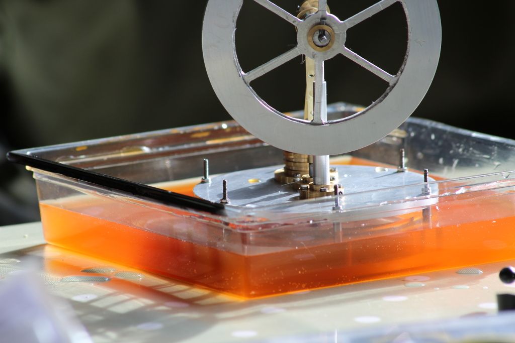
                                                    Wow guys, thanks very much. I repeated the leak test using water with a drop of washing-up liquid to make it wetter and some red food dye to make it easier to see. The engine's lower plate was immersed for 5 minutes.

                                                    bath.jpg

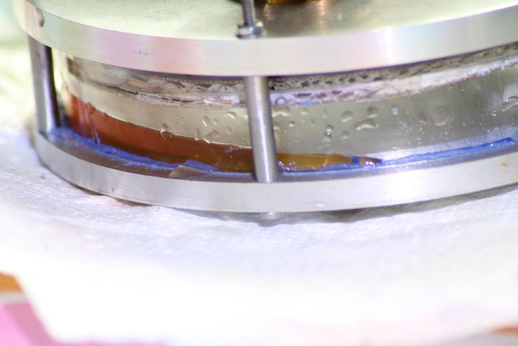
                                                    The result may explain why the engine wouldn't run yesterday.  (Water Hammer!)

                                                    failed.jpg

                                                    The cardboard displacer was ruined.

                                                    Stripping down the engine revealed more problems due to acetic acid corrosion. See what it did to the polish of the power cylinder bore!

                                                    boredamage.jpg

                                                    It looks worse than it is, fortunately Duraglit made a huge improvement. The end of the piston was rusted again but the damage isn't serious.

                                                    I went out and bought Balsa and a Flat `At. Wearing a traditional cap in the workshop will multiply my meagre skills. Sadly I found that my traditional local ironmonger has stopped trading and I was unable to easily buy more silicone sealant.(I've gone off RTV Instant Gasket because of the fumes.) I've decided temporarily to use modelling clay as a sealant. It 's like plasticene but rather softer. I use it very successfully it to weather protect the nuts and bolts of an antenna system: it's clean, lasts outside for years and is easy to remove.

                                                    Noting advice above. I'm off to make a balsa displacer. Now I've spent money because of it I fully expect to fall over the missing polystyrene in the next 5 minute. I have the wherewithal to make a hot-wire cutter and may well end up trying it. Some of the other ideas are now in a queue because I don't want to change too many things at once.

                                                    Very many thanks for the intel that the engine works but is difficult possibly due to a design issue. I'm starting to feel that everything has to be "just so" before it will run. Watch this space!

                                                    Cheers,

                                                    Dave


                                                    Edited By SillyOldDuffer on 03/03/2016 16:50:44

                                                    Edited By SillyOldDuffer on 03/03/2016 16:53:38

                                                    #228095
                                                    Ajohnw
                                                    Participant
                                                      @ajohnw51620

                                                      Brave man Mark. Don't blame you though. Mig wire appealed to me because I had an old valve filament transformer around. Volts too high but power ok. It would have been a lot more tricky to use resistance wire and low voltages.

                                                      However using this

                                                      **LINK**

                                                      I've just ordered some of this

                                                      **LINK**

                                                      I've used them before for kanthal wire.

                                                      I've based it around 15" of wire and 5 volts. 350C and circa 4 amps. This works out at 1 1/3 watt per inch of wire which is close to figures I have seen. I used 15" to allow for some shortening if needed. The wire is about 1 ohm per foot. They sell kanthal as well. 0.7mm dia has a similar resistance value.

                                                      John

                                                    Viewing 25 posts - 1 through 25 (of 132 total)
                                                    • Please log in to reply to this topic. Registering is free and easy using the links on the menu at the top of this page.

                                                    Advert

                                                    Latest Replies

                                                    Home Forums Beginners questions Topics

                                                    Viewing 25 topics - 1 through 25 (of 25 total)
                                                    Viewing 25 topics - 1 through 25 (of 25 total)

                                                    View full reply list.

                                                    Advert

                                                    Newsletter Sign-up