Isochronous knife edge suspension?

Advert

Isochronous knife edge suspension?

Home Forums Clocks and Scientific Instruments Isochronous knife edge suspension?

Viewing 25 posts - 76 through 100 (of 142 total)
  • Author
    Posts
  • #659132
    Michael Gilligan
    Participant
      @michaelgilligan61133

      I give up

      Advert
      #659299
      david bennett 8
      Participant
        @davidbennett8

        Just a practical observation, for if anyone else is investigating this idea –

        It seems that the magnets need to be circlar in shape, and probably set into shallow "pockets" cut into the rollers. If the magnets are not held central they can accelerate as they near steel plate and upset the timing.

        dave8

        #659300
        david bennett 8
        Participant
          @davidbennett8

          I've just had a very dispiriting thought –

          If tthese "coins" do not give a cycloidal movement to the pendulum, then the whole idea will not work. I can see no way to centralise the magnets on a shoe that is not circular.

          dave8

          #659381
          david bennett 8
          Participant
            @davidbennett8

            I am abandoning this build. Any imbalance in the magnets will interfere with the gravitational effect on the pendulum. It is therefore impractical.

            dave8

            #659431
            david bennett 8
            Participant
              @davidbennett8

              If I may clarify my decision without intending to upset anybody – None of your formulae take account of the influence of magnetising the roller or the shoe. Compare a non magnetised set-up with a magnetised one. At each end of a swing, one arm of a magnetised curved shoe is in close contact with a steel plate.the other (balancing) arm is some distance away.The "reluctance" of the magnet to let go will greatly affect the natural motion of the pendulum. This will happen at the other extreme too.I think that this is another example of a close look at what is actually happening serves better than blindly following the accepted formulae.

              dave8

              #659440
              Michael Gilligan
              Participant
                @michaelgilligan61133

                Well done for posting that explanatory note, dave8 yes

                … it will be helpful to anyone thinking along similar lines in the future.

                MichaelG.

                .

                I should perhaps add that I had deliberately ignored the complexities around the use of magnets … basically because my interest was the geometry.

                #659452
                SillyOldDuffer
                Moderator
                  @sillyoldduffer
                  Posted by david bennett 8 on 07/09/2023 04:03:17:

                  … I think that this is another example of a close look at what is actually happening serves better than blindly following the accepted formulae.

                  dave8

                  Formula are models attempting to simulate the real world. They are correct, or at least "good enough" provided their limitations are recognised.

                  The period formula assumes that the pendulum is rigidly mounted on solid ground, has a frictionless suspension, temperature and pressure are constant; and there are no other external forces in play. My cat is a menace!

                  Suspending a pendulum from a magnetically attracted roller is likely to cause trouble because, even if it causes the bob to swing isochronously, the suspension is unlikely to be rigid or low friction. (Reluctance is Friction)

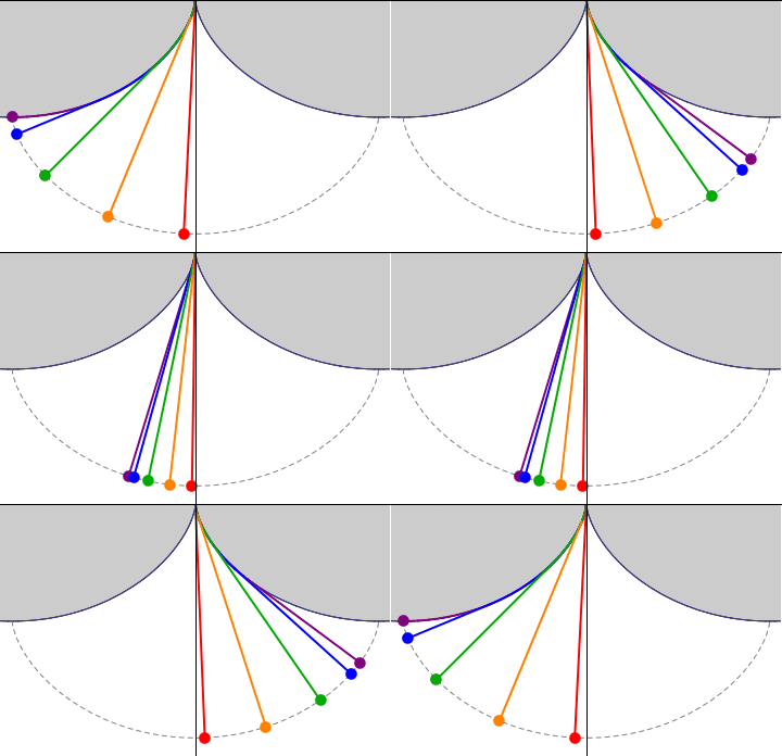
                  The energy lost due to friction whilst bending the suspension scuppered Huygens cheeks, even though the geometry produces isochronous beats:

                  Easier to build a clock with an ordinary pendulum and run it at low amplitude (red example above). Near bottom dead centre the curve followed by the bob is nearly isochronous. It's a good practical compromise because the amplitude error is small. I believe Fedchenko is the only person to make a satisfactory low friction isochronous suspension. So far!

                  All practical clocks break the pendulum formula to some degree because real-world engineering is always imperfect. Mathematical models are still useful though. Comparing the behaviour of an engineered solution with that predicted by formulae perfect in theory often reveals where engineering effort on improvements is most needed. Or the experiment might reveal that the formula isn't quite right, and it has to be changed. Practical men are far too inclined to dismiss theory, leaping to the conclusion that a few failed misunderstanding prove conclusively that 'expurts' know nothing. Practical men get stuff wrong too.

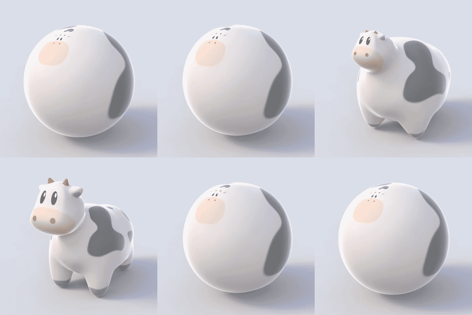
                  The shortcomings of formula as models are the subject of much humour in the scientific community, notably the many variations of the Spherical Cow joke. This example pinched from Wikipedia.

                  Milk production at a dairy farm was low, so the farmer wrote to the local university, asking for help from academia. … Shortly thereafter a theoretical physicist returned to the farm, saying to the farmer, "I have the solution, but it works only in the case of spherical cows in a vacuum."

                  I think the magnetic suspension idea has merit, but it will be hard to make it work.

                  Dave

                  #659462
                  John Haine
                  Participant
                    @johnhaine32865

                    "All models are wrong, but some are useful." https://en.wikipedia.org/wiki/All_models_are_wrong

                    Magnetic "reluctance" has a specific meaning, being the relationship between field (measured in amps/metre) and flux (tesla) in a magnetic circuit. It isn't a measure of the magnetic attraction or "reluctance to let go".

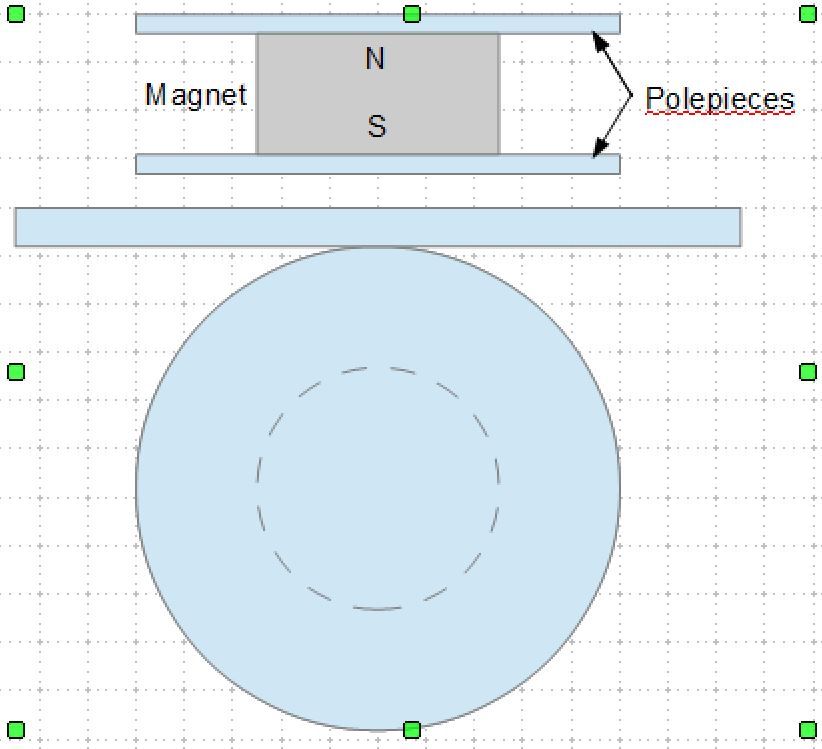
                    mag_roller.jpg

                    This is my mental picture of the arrangement. The rollers are two soft steel discs that form polepieces for a strong short cylindrical magnet mounted coaxially between them. If the contact is good virtually all the flux from the permanent magnet will flow through the polepieces, and establish a magnetic field in the space outside them, mainly concentrated in the air gap.

                    The lower picture shows this hanging from a flat soft magnetic plate. Since the plate and discs are in contact at the tangent point, most of the actual flux will flow through this point as that is the path of minimum reluctance. There will be some flux in the gap close to the contact point but it will fall off rapidly with distance. If there was any imbalance between the forces on each side of the contact point then the roller would move on its own – symmetry ensures it won't move.

                    In a real suspension the radius of the discs would be much larger and we will only need a small proportion of the circumference, but if we made sure that there was enough that the movement of the contact point is only a small proportion of the width I would guess there would still be no net magnetic force – given a suitable field analysis program we could compute this.

                    So I don't think that it's obvious that the system won't work at least from a magnetics point of view.

                    Edited By John Haine on 07/09/2023 11:43:50

                    #659484
                    duncan webster 1
                    Participant
                      @duncanwebster1

                      I'm with John, I think it works in principle. The difficulty is stopping it going walkies. My only suggestion is a set of very thin metal tapes wrapped round curved members coaxial with the pole pieces.

                      #659486
                      Tony Jeffree
                      Participant
                        @tonyjeffree56510

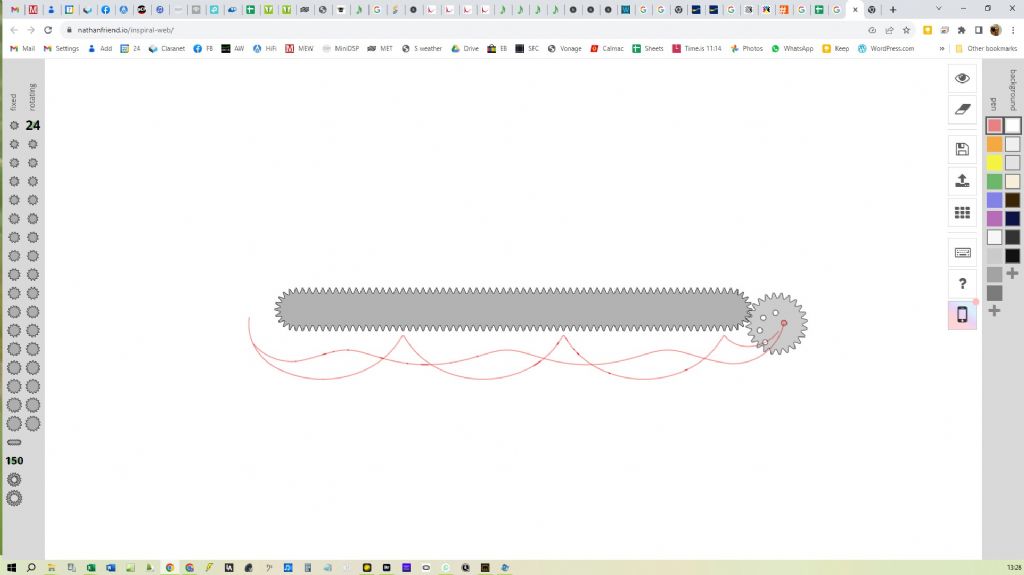
                        Just in case there is still any doubt about what is going on here, it might be worth digging out your old Spirograph set and playing with that. I found an online Spirograph sim that illustrates the point with a tad of imagination:

                        untitled.jpg

                        The two traces in the pic are formed by (1) using a point close to the circumference of the roller (trace near enough cycloidal), and (2) a point close to the centre of the roller (trace approaching a flat line). It will be no surprise that if you trace the path of the centre of the roller, it would actually be a straight line. What the sim doesn't allow, but which you could do with a real spirograph, is to strap a larger wheel onto the smaler one to allow you to see what happens when you trace a point that is outside the circumference of the roller – e.g., a point on the "bob". It doesn't take much to visualise what the trace looks like – apart from anything else, on each full rotation it passes through the horizontal plane, performs a retrograde loop, and then passes back through the horizontal plane.

                        #659487
                        John Haine
                        Participant
                          @johnhaine32865

                          Tony, nice! What is the tool called please?

                          #659488
                          Tony Jeffree
                          Participant
                            @tonyjeffree56510

                            https://nathanfriend.io/inspiral-web/

                            Incidentally, my observation that the centre of the roller follows a straight line should tell you that the centre of mass of the bob needs to be on the circumference of the roller (earlier on there was some uncertainty as to whether the roller radius or diameter should equal the pendulum length – clearly it has to be the diameter, or the bob would travel a straight line path.)

                            Edited By Tony Jeffree on 07/09/2023 13:52:47

                            #659490
                            Tony Jeffree
                            Participant
                              @tonyjeffree56510

                              Of course, a moment's thought about the wheels on a car would have brought you to the same conclusion. A point on the tread follows a near-enough cycloidal path (give or take the flexibility of the tyre), but you'd better hope that the wheel axle doesn't follow a cycloid, or it is going to be a rather bumpy ride!

                              Edited By Tony Jeffree on 07/09/2023 14:05:35

                              #659495
                              Michael Gilligan
                              Participant
                                @michaelgilligan61133

                                Tony

                                As you have so obviously got a grip on all of this … Would you please do me the favour of reading Huygens’ description of his layout process; and then explain exactly the result what he is doing ?

                                Something in it doesn’t quite ring true

                                The English translation of text is on the page that I posted

                                28/08/2023 16:15:31

                                But, for everyone’s convenience, I will post the transcription of the Latin and IanBruce’s translation shortly.

                                It all seems consistent in itself, but …

                                MichaelG.

                                #659496
                                Michael Gilligan
                                Participant
                                  @michaelgilligan61133

                                  Huygens:

                                  Super tabula plana affigatur regula A B, semidigiti crassitudine. Deinde fiat cylindrus C D E eadem illa altitudine, diametrum vero baseos, dimidiae perpendiculi longitudini, aequalem habens; sitque F G H E fasciola, seu potius bractea tenuis, affixa regulae in huic F, cylindro vero in circumferentiae puncto aliquo E, ita ut partim huic circumvoluta sit, partim extendatur juxta latus regulae A B. Cylindro autem infixa sit ferrea cuspis D I, pauxillum ultra basis inferiorem prominens, atque ita ut circumferentiae ejus exacte respondeat. [p. 11]

                                  His ita se habentibus, si cylindrus secundum regulum A B volvatur, bracteolae tantum FG crassitudine intercedente, eaque semper quantum potest extensa, describet cuspis I subjecto tabulae plano lineam curvam KI, quae Cyclois vocatur. Circulus vero genitor erit CDE, cylindri adhibiti basis. Quod si jam laminam KL ad regulam A B applicuerimus; exarata primum ea cycloidis portione K I, invertemus deinde ipsam, & in superficie adversa similem lineam K M, ab eodem puncto K egredientem, incidemus. Tum figuram MKI, accurate secundum, lineas istas, efformabimus, cui figurae lamellarum interstitium aptari oportet, inter quas per pendiculum suspenditur. Sufficiunt autem ad horologiorum usum portiones exiguae arcuum K M, K I; reliquo flexu inutili futuro, ad quem perpendiculi filum accedere non potest. Verum, ut mirabilis lineae natura atque effectus plenius intelligantur, integras semicycloides KM, KI, alio schemate hic exprimere visum fuit, inter quas suspensum agitatumque Pendulum KNP, diametri circuli genitoris duplum, cujuscunque amplitudinis oscillationes, usque ad maximam omnium per arcum MPI, iisdem temporibus confecturum sit: atque ita, ut appensae spherae P centrum, in linea M P I, quae & ipsa cyclois integra est, semper versetur. Quae proprietas insignis nescio an alii praeter hanc lineae data sit, ut nempe se ipsam sui evolutione describat. Haec autem quae dicta sunt, in sequentibus, ubi de descensu gravium, deque evolutione curvarum agemus, singula demonstrabuntur. [p. 12]

                                  #659497
                                  Michael Gilligan
                                  Participant
                                    @michaelgilligan61133

                                    Ian Bruce:

                                    Upon a flat table the rule AB is fixed, half a finger wide. Then there is present a cylinder C D E truly with the diameter of the base equal to half the length of the pendulum; and F G H E is a small bandage, or better a thin metal foil, fixed to the rule at the point F of this, and to some point of the circumference of the cylinder E, thus in order that it shall be partially wrapped around the cylinder alongside the rule A B. Moreover a sharp iron point DI shall be fixed to the cylinder, projecting a little below the base, and thus in order that the circumference of the cylinder corresponds exactly to it. [p. 11]

                                    Thus with these in place, if the cylinder is rotated along the rule A B, with the metal foil in between as far as FG, and with that always extended as far as possible, the sharp point I applied below on the plane table will describe the curved line KI, which is called the cycloid. Truly the circle CDE is the originator of the curve, applied to the base of the cylinder. Since if now we apply the plate KL to the rule A B ; that first part of the cycloid KI is traced out, then we invert the plate, and in the facing surface the similar curve KM is inscribed, arising from the same point K. Then we will have formed the figure MKI, following these lines carefully for the figure of the plates it is necessary to adapt, through the gap between which the pendulum is hanging. Moreover the small portions of the arc KM, KI are sufficient for the use of the clocks ; with the remainder of the curve not to be used in the future, and to which the string of the pendulum does not have access. Truly, in order that the wonderful nature of the line and the effect may be understood better, the whole semicycloids KM and KI, here seen to be expressed by another diagram, between which the pendulum KNP is suspended and moving, [of length] twice the diameter of the generating circle, and the oscillations of any amplitude, as far as the largest of all through the arc MPI will be made in the same times : and thus, so that the centre P of a sphere hung on, is always moving to and fro on the line M P I which is part of a whole cycloid. I do not know of any other line with this conspicuous quality, except for this given line, as truly it describes its own evolute. Moreover these things which have touched on, concerning the descent of the weight and the evolute of the curve, we will go through and each will be explained in what follows. [p. 12]

                                    #659498
                                    Michael Gilligan
                                    Participant
                                      @michaelgilligan61133

                                      The translation is obviously into spoken English, but the important words appear to correspond nicely to the Latin.

                                      So the big problem is:

                                      with the diameter of the base equal to half the length of the pendulum

                                      MichaelG.

                                      #659499
                                      david bennett 8
                                      Participant
                                        @davidbennett8

                                        Visualise a series of concentric circles, each distorted at the base by their appropriate cycloid . draw that on a card and pin it's centre to the axis of the 2p . Compare

                                        pendulum paths of a large circle and a small one (2p size )

                                        dave8

                                        Edited By david bennett 8 on 07/09/2023 16:28:54

                                        #659505
                                        david bennett 8
                                        Participant
                                          @davidbennett8

                                          John, I was aware of problems with using "reluctance",but I was using in the non-scientific way. I did search for another word to convey my meaning, but still cannot think of one.

                                          dave8

                                          Edited By david bennett 8 on 07/09/2023 17:51:06

                                          #659508
                                          SillyOldDuffer
                                          Moderator
                                            @sillyoldduffer
                                            Posted by david bennett 8 on 07/09/2023 17:50:36:

                                            John, I was aware of problems with using "reluctance",but I was using in the non-scientific way. I did search for another word to convey my meaning, but still cannot think of one.

                                            dave8

                                            Neither can I, which is why I said your reluctance is friction, in the sense extra force is needed to get a mass moving. Remanence and stiction are both wrong and I'm not happy with drag. I expect the Greeks had a word for it!

                                            Dave

                                            #659510
                                            John Haine
                                            Participant
                                              @johnhaine32865

                                              "extra force is needed to get a mass moving"…inertia?

                                              #659513
                                              Mike Everman
                                              Participant
                                                @mikeeverman73009

                                                Some random comments:

                                                I tried the magnet/hoop thing and fringe effects dominated near the ends of the bar, as well as substantial eddy current damping, like imagine a Q of 2. Then, my simplistic EM drive was pulling on the steel of my bob, and through the data, I realized that the electromagnet was very slowly magnetizing the bob. Though the rate looked to be leveling off, it was in my tedious pre Microset days. I then just spent all my time on non-magnetic approaches, and have learned from recent experience that NdFeB magnets change quite radically with temperature.

                                                This drives you to conceptually flip everything over and look at the rod as a support instead of a tension member, as it all must translate in the direction of swing.

                                                If the bob is free to rotate, or more precisely, does not rotate with respect to ground, then every atom will follow the cycloid you've defined by whatever means. If it is rigid, all bets are off, and there is .

                                                As I recall, what killed the cheeks on Huygen's pendulum was the energy lost rotating a rigid bob and rod below the silk threads. I believe Alan Emmerson wrote a definitive proof of how a compound pendulum could never use cycloidal cheeks for isochronism. My takeaway from that was, "Oh, I just need to make a massless rod and a point mass. Simple!"

                                                #659523
                                                Tony Jeffree
                                                Participant
                                                  @tonyjeffree56510
                                                  Posted by Michael Gilligan on 07/09/2023 15:54:32:

                                                  Tony

                                                  As you have so obviously got a grip on all of this … Would you please do me the favour of reading Huygens’ description of his layout process; and then explain exactly the result what he is doing ?

                                                  Something in it doesn’t quite ring true

                                                  The English translation of text is on the page that I posted

                                                  28/08/2023 16:15:31

                                                  But, for everyone’s convenience, I will post the transcription of the Latin and IanBruce’s translation shortly.

                                                  It all seems consistent in itself, but …

                                                  MichaelG.

                                                  Michael

                                                  I certainly don't claim to have a grip on all of this! My observations above relate only to the discussion of the roller-with-attached-pendulum-suspended-under-a-(magnetic)-plane model – for that model to work you would (I believe) need the roller diameter to equal the effective pendulum length.

                                                  The Huygens approach seems to be to use cycloidal cheeks – which reduce the pendulum's effective length as the amplitude increases. I've yet to try to get my head round why he chooses 1/2 the pendulum length to generate the curves for the cheeks.

                                                  Regards,

                                                  Tony

                                                  #659527
                                                  duncan webster 1
                                                  Participant
                                                    @duncanwebster1

                                                    It's covered in this article from Wikipedia. If it has stood the test of 300 years, and mathematicians such as Lagrange and Euler have been involved in providing proofs I think we can take it as read.

                                                    To save flogging through it the significant sentence in my view is

                                                    there were much more significant sources of timing errors that overwhelmed any theoretical improvements that traveling on the tautochrone curve helps. Finally, the "circular error" of a pendulum decreases as length of the swing decreases, so better clock escapements could greatly reduce this source of inaccuracy.

                                                    In other words, keep the amplitude low and constant and forget about isochroism (if there is such a word)

                                                    #659528
                                                    Mike Everman
                                                    Participant
                                                      @mikeeverman73009

                                                      Preaching to the choir and just getting my thoughts straight, but an isochronous approach would only be useful on a free pendulum. Making it less concerned about amplitude allows you to impulse it less often. A traditional escapement would need to unlock and impulse perfectly centered for it to benefit from this, right?

                                                    Viewing 25 posts - 76 through 100 (of 142 total)
                                                    • Please log in to reply to this topic. Registering is free and easy using the links on the menu at the top of this page.

                                                    Advert

                                                    Latest Replies

                                                    Viewing 25 topics - 1 through 25 (of 25 total)
                                                    Viewing 25 topics - 1 through 25 (of 25 total)

                                                    View full reply list.

                                                    Advert

                                                    Newsletter Sign-up