Is CAD for Me?

Advert

Is CAD for Me?

Viewing 25 posts - 151 through 175 (of 178 total)
  • Author
    Posts
  • #415529
    Anonymous
      Posted by Nigel Graham 2 on 21/06/2019 23:23:50:

      Even an equal pair of bevel wheels isn't easy to measure and draw though!

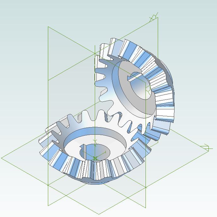
      Not difficult, but you do need a good understanding of gear design, like this:

      governor bevel gear assembly 16 tooth.jpg

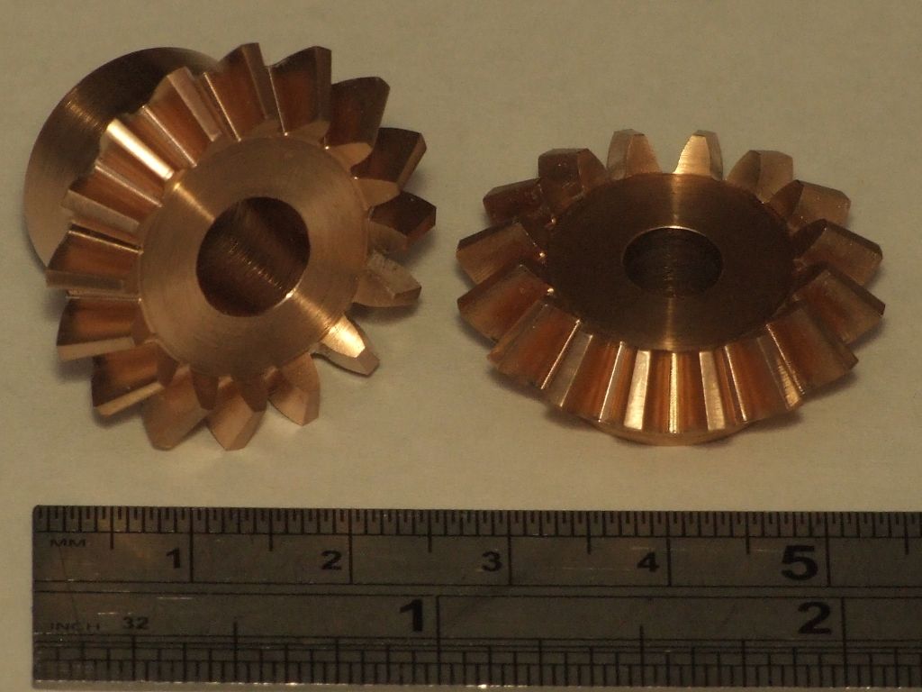
      And after machining on a CNC mill:

      governor bevel gears.jpg

      Andrew

      Advert
      #415532
      JasonB
      Moderator
        @jasonb

        Also not to hard to model a reasonable visual representation even if you don't want or need the exact profile

        bevel 5.jpg

        #415533
        Nigel Graham 2
        Participant
          @nigelgraham2

          Blowlamp –

          I had that idea from the sites referred to above. The publishers like to show their software's maximum capabilities. Whilst I understand that, I find it a bit off-putting even though I know the artwork is by the publisher's professional designers pushing the software to its limits.

          The packaging for my copy of TurboCAD contains a card advertising the agent (Paul Tracey). He used on it, rather more down-to-Earth, 3D images of assemblies for a miniature locomotive: a 4-wheel bogie in plain view with moderate tinting, a luridly rendered pony-truck, and the boiler manifold in wire-frame view. The last is so "busy" it loses details.

          Barrie –

          CNC cutting or Printing – either way, my point was I took MOI as primarily for CAM files. However, CNC machining or printing is not available to me; and I need primarily orthographic engineering drawings, with isometric views potentially useful but not so important.

          '

          Impressive examples you give though. You designed the aircraft parts in MOI, but I take it BobCAD is essentially the machine-tool programmer building tool-paths etc. around the MOI file?

          I like that aid to clarity shown in the second screen-shot, by tinting different parts of a wire-frame assembly. I've found colours particularly valuable in an assembly-drawing when I need pick out individuals of repeated components in crowded elevations. If left in one colour, the drawing starts to resemble well-boiled spaghetti.

          Recently I completed some structural-geology diagrams in 3D, using colours to differentiate the strata represented geometrically by extrusions. One looked very odd, as if the bed of rock had been mined out of the hill. Then light dawned: to make that layer white and solid, fill its generating shape with white from the colour-chart, not just leave it empty (" white " on the screen).

          #415543
          Former Member
          Participant
            @formermember32069

            [This posting has been removed]

            #415547
            blowlamp
            Participant
              @blowlamp
              Posted by Nigel Graham 2 on 22/06/2019 10:26:00:

              Blowlamp –

              I had that idea from the sites referred to above. The publishers like to show their software's maximum capabilities. Whilst I understand that, I find it a bit off-putting even though I know the artwork is by the publisher's professional designers pushing the software to its limits.

              The packaging for my copy of TurboCAD contains a card advertising the agent (Paul Tracey). He used on it, rather more down-to-Earth, 3D images of assemblies for a miniature locomotive: a 4-wheel bogie in plain view with moderate tinting, a luridly rendered pony-truck, and the boiler manifold in wire-frame view. The last is so "busy" it loses details.

              Barrie –

              CNC cutting or Printing – either way, my point was I took MOI as primarily for CAM files. However, CNC machining or printing is not available to me; and I need primarily orthographic engineering drawings, with isometric views potentially useful but not so important.

              '

              Impressive examples you give though. You designed the aircraft parts in MOI, but I take it BobCAD is essentially the machine-tool programmer building tool-paths etc. around the MOI file?

              I like that aid to clarity shown in the second screen-shot, by tinting different parts of a wire-frame assembly. I've found colours particularly valuable in an assembly-drawing when I need pick out individuals of repeated components in crowded elevations. If left in one colour, the drawing starts to resemble well-boiled spaghetti.

              Recently I completed some structural-geology diagrams in 3D, using colours to differentiate the strata represented geometrically by extrusions. One looked very odd, as if the bed of rock had been mined out of the hill. Then light dawned: to make that layer white and solid, fill its generating shape with white from the colour-chart, not just leave it empty (" white " on the screen).

              I can see that CAD isn't for you. You make assumptions and then wonder why nothing works for you

              It's not possible to gain any reasonable overview of MoI from the link you have referred to as it's just there to give a an idea of MoI's capabilities if you have the skill to make use of them. It simply says MoI is easy to use, but is capable of complex things for the more adventurous user.

              #415548
              blowlamp
              Participant
                @blowlamp
                Posted by Barrie Lever on 22/06/2019 11:22:49:

                Nigel

                Well MOI is just very good at creating 3D models, you can then use that 3D model for a fancy illustration or to go to manufacturing (machining or printing)

                Alibre, Solidworks or Fusion 360 would beat MOI for the bevel gear illustrated by Andrew and Jason, although MOI would do the job. MOI would beat Fusion, Alibre and Solidworks for producing a very organic surface model like the wingtip of the model plane.

                You are correct, BobCAD produces the tool paths over the 3D model, 70% of CAM packages use the same Kernel or Engine (I prefer to call it the heart) which comes from a German company called Moduleworks, so you do hear some right old rubbish spoken about one CAM package being better than another when actually in 70% of the cases we are talking about the same thing. BobCAD uses the Moduleworks kernel.

                I use the following CAD packages

                • Bricscad (good AutoCAD clone) for very high quality 2D drawings with full annotations etc.
                • MOI for very organic shapes ( and being a 3D CAD viewer)
                • Alibre for mechanical prismatic type models and assemblies such as the bevel gear.
                • BobCAD for single 3D models not in assembly that will be machined.

                If I could only have one 3D CAD package and I was not going to machine parts then I would go for MOI, if I could only have one 3D CAD package and I had to machine parts using that CAD package to produce G code then it would be BobCAD.

                I think Solidworks proabably comes closest to being an all round do everything package but I dont like the price circa £5000 plus VAT and I have a heavy time investment in the CAD packages that I use already.

                Fusion 360 is out for me as I also use the CAD commercially and I am above the commercial cut off point, also at some stage the freebe side of Fusion 360 will get withdrawn IMO.

                Regards

                Barrie

                I did a bevel gear in MoI a while ago.

                #415600
                Nigel Graham 2
                Participant
                  @nigelgraham2

                  I must admit I've often wondered how close to each other all these programmes are, behind the trade-marks and patented / copyrighted presentation.

                  That bevel gear is actually very much like the ones I am using.

                  To make the assembly work I need join them by a central journal that also prevents the axial thrust on one of them from pushing it out of mesh. I have established the most compact arrangement for that.

                  This particular gear-drive is not too fussy, but I'd like it to be right both for itself, and experience should I wish to make a more critical version in future.

                  Techniques for drawing gears accurately (irrespective of draughting method) are described in my text-books. Here though I need know only the pairs' relationship and overall dimensions when meshed. I'm not trying to design the wheels themselves.

                  I could draw the journal isometrically as it's only a rectangular block with a few cylindrical features, all symmetrical; but I need an orthographic drawing for making it.

                  '

                  To those who say CAD's not for me, I want it for me. I want to be able to use CAD sufficiently to support my model-engineering.

                  Unfortunately I find the CAD publishers' web-sites are very off-putting by suggesting overwhelming complexity and difficulty. That and the lack of any decent literature on the subject, make me feel like, say, a 'celebrity' pop-singer told you can learn to sing from a Wagnerian opera score!

                  #415645
                  Gary Wooding
                  Participant
                    @garywooding25363
                    Posted by Barrie Lever on 22/06/2019 11:22:49:

                    Nigel

                    Well MOI is just very good at creating 3D models, you can then use that 3D model for a fancy illustration or to go to manufacturing (machining or printing)

                    Alibre, Solidworks or Fusion 360 would beat MOI for the bevel gear illustrated by Andrew and Jason, although MOI would do the job. MOI would beat Fusion, Alibre and Solidworks for producing a very organic surface model like the wingtip of the model plane.

                    … CLIP

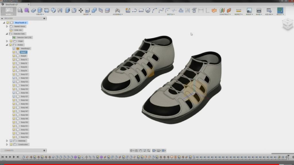
                    How about these shoes, produced entirely in Fusion.

                    shoes.jpg

                    #415651
                    Former Member
                    Participant
                      @formermember32069

                      [This posting has been removed]

                      #415655
                      Nigel Graham 2
                      Participant
                        @nigelgraham2

                        " … from tracing over photos …"

                        Via a scanner? I don't know if such software exists, but it could be very useful, being able to translate a scanner file into a CAD one.

                        '

                        Re-measured and re-drew my bevel-gears this evening. The measuring was a bit of a faff, but I concocted a way using a small angle-plate and the drilling-machine table; and the new drawing is much closer than my preliminary attempt.

                        I didn't try to draw the teeth, just the overlapped outlines, in different colours for legibility. I could then add the bearing-block, shaft-ends and thrust collar to hold them together. Drawing the assembly upside down synthesised how I'd measured it, replacing the metal surfaces with the axes, so all the co-ordinate values are positive.

                        I've still to establish how to make the dimensions work, but I now know how to assemble adjoining drawing entities, in 2D anyway!

                        #415675
                        Gary Wooding
                        Participant
                          @garywooding25363

                          Barrie.

                          Fusion has a facility called Attached Canvas, which allows you to insert images onto any plane or surface you like. Each image can be scaled as needed and used to guide the creation of the model features required. The visibility of attached canvases can be controlled independently, from the model, and from each other. The opacity of any canvas or model can be controlled from almost transparent to fully opaque.

                          I don't know MOI, but from the video it would appear that organic shapes are created from sets of contour lines defined as splines. Fusion is quite different. It has a facility known as T-splines which allow the direct creation and modification of surfaces in 3D – rather like moulding sheets of clay. That's how the shoes were created. I would like to make it clear that I didn't create the shoes – I'm nowhere near that level of expertise.

                          #415694
                          Former Member
                          Participant
                            @formermember32069

                            [This posting has been removed]

                            #415697
                            Former Member
                            Participant
                              @formermember32069

                              [This posting has been removed]

                              #416166
                              Nigel Graham 2
                              Participant
                                @nigelgraham2

                                Barrie –

                                I asked about scanners following your remark about photos.

                                That could have even helped my own project, as I have nothing but old archive photos and a few dimensions.

                                The big difficulty though, is a photo is usually at unknown angles to its subject, and from an unknown distance, so simply scanning it would give a distorted result. If the subject is long, such as railway locomotive or a building, the photo may also be affected by perspective.

                                I recall an article a long time ago, I think in ME, that described how to correct for these manually, provided you know a few key dimensions. For the locomotive this may be the coupled-wheel diameter (by its height, if all visible) and track gauge.

                                For my wagon, I used the wheel diameters and overall length and width, quoted in old trade reviews, but to make it more fun, E.S Hindley & Sons did not appear to worry too much about standardising theri products, and the reviews' illustrations were not necessarily of the wagon the reviewers test-drove!

                                I don't know if the software you describe can correct for both of these distortions.

                                As far as I am aware, TurboCAD doesn't read scanner files, which are images types at least from my scanner; but I think it will accept other drawing files. Its default saving is in its own " .tcw " format; but you can save its fully-rendered pictures as .bmp (and .jpg?) images.

                                +

                                Alibre's sales people don't seem to talk to their agents, but they do want you to buy their software!

                                A lady from its own American offices no less, asked me yesterday how I was progressing with the trial.

                                I replied I had failed; explained why, and that as the trial and its licence have expired I'd now have to buy the full version but it would be silly to spend £250 on something I can't learn! Then added I had already deleted Alibre from my computer ("Deleted" it, files and folders, as I could not remember how to "uninstall" it.)

                                I'm not expecting a reply of course, but I would not surprised if she tries to persuade me otherwise, since she is paid to sell it.

                                #416169
                                Tomfilery
                                Participant
                                  @tomfilery

                                  Nigel,

                                  Although TurboCad won't read your image files directly, you can insert them into a "drawing".

                                  I frequently insert images (usually jpeg ones, perhaps copied from a book, or magazine) into a drawing, then blow them up to the correct size for my project. You often have to scale them separately for X and Y and most drawings do have some degree of distortion, so you won't be able to "trace" an image ultra accurately.

                                  I usually draw my drawing, based upon the information in the image, then move the image over the drawing to check it looks about right.

                                  Have done it with all sorts of locos and rolling stock – even used it to draw out a wagon, based on a few key measurements and a photograph.

                                  Regards Tom

                                  #416174
                                  Neil Wyatt
                                  Moderator
                                    @neilwyatt
                                    Posted by Tomfilery on 26/06/2019 11:11:29:

                                    Nigel,

                                    Although TurboCad won't read your image files directly, you can insert them into a "drawing".

                                    I frequently insert images (usually jpeg ones, perhaps copied from a book, or magazine) into a drawing, then blow them up to the correct size for my project. You often have to scale them separately for X and Y and most drawings do have some degree of distortion, so you won't be able to "trace" an image ultra accurately.

                                    I usually draw my drawing, based upon the information in the image, then move the image over the drawing to check it looks about right.

                                    Have done it with all sorts of locos and rolling stock – even used it to draw out a wagon, based on a few key measurements and a photograph.

                                    Regards Tom

                                    That's exactly how I did the drawings for much of my Southam loco.

                                    Neil

                                    #416182
                                    SillyOldDuffer
                                    Moderator
                                      @sillyoldduffer

                                      Posted by Nigel Graham 2 on 26/06/2019 10:51:42:

                                      A lady from its own American offices no less, asked me yesterday how I was progressing with the trial.

                                      I replied I had failed… Then added I had already deleted Alibre from my computer ("Deleted" it, files and folders, as I could not remember how to "uninstall" it.)

                                      Deleting files manually is liable to leave a mess causing mysterious trouble later.

                                      Problem is that Install usually does more than simply copy files and folders to your computer. For example, on Windows, an Installer is likely to put DLL's into system folders and update the registry. It might also monkey with permissions and other internal system features the owner is unlikely to understand.

                                      Usually best to Uninstall software as recommended by the vendor.

                                      Dave

                                      #416183
                                      Nigel Graham 2
                                      Participant
                                        @nigelgraham2

                                        Thankyou Tom.

                                        I didn't know you can do that!

                                        It's not something really covered in the only two CAD "primers" I have found anywhere, by DAG Brown and more recently, Neill Hughes; and sold by our very valuable specialists, TEE Publishing

                                        I don't think Mr. Brown describes it at all; whilst Mr. Hughes tells us more what can be done than how to do it. His example of using a scanned 2D drawing to guide the CAD version seems much as you describe, and he notes the value of the original drawing's scale-bar.

                                        Hughes also mentions 3D scanning, but only briefly and fairly clearly as what's done industrially. In fact his book's sparse bibliography lists only reference-works for professional designers and production-managers. Having said that, versions of such books written early in the 20C are very useful when trying to replicate an Edwardian machine without its original drawings, for showing contemporary practices, component proportions, etc.

                                        If really stuck I have sometimes gauged details by parts that need literally be measured in "hands" (well, the machine develops or absorbs 'horsepower ' … ) and other anthropocentric proportions, such as handrails, steps and the grips on the ends of levers. Essentially, think in likely full size, and how it was operated, first.

                                        #416187
                                        JasonB
                                        Moderator
                                          @jasonb

                                          Nigel, although it does not go into much detail about the initial working from a scanned drawing this thread is a good example of all the CAD, CAM, 3D printing, CNC, etc methods coming together to make a model pump.

                                          #416214
                                          Nigel Graham 2
                                          Participant
                                            @nigelgraham2

                                            Jason –

                                            I am impressed! I can still appreciate the skill involved even though disappointed by my attempts.

                                            I've know for a long time you can make machine-control files from CAD drawings but I hadn't known you can translate even images like that catalogue engraving into the CAD drawing to start with.

                                            I read their remarks about the distortion given by the angle of view, and so used known vertical heights to start establishing the correct horizontal dimensions.

                                            I don't think the SolidWorks and AutoCAD they used are available to private customers in the UK, but I imagine you can use Alibre or Fusion for similar? (Fusion and AutoCAD are by the same company anyway.)

                                            I first met CAD as SolidWorks, at work, but just by observation not experience; around the time TurboCAD was being advertised in ME. It was there too that I encountered the practice of putting a pictorial rendering in the corner of the orthographic drawing, to help visualise the work-piece. Hemingway Kits follow the same practice.

                                            '

                                            SillyOdDuffer –

                                            Thank for you for that advice. I found "Uninstall " eventually. However, it could not remove Alibre because it could not find what I assume are Alibre components. I tried to repair / recover the programme to uninstall it properly, but to no avail.

                                            So I am stuck with a programme I wanted gone because I could not use it, but I've now damaged so badly it cannot be used, repaired or removed anyway! I will have to hope it just lies there and causes no trouble.

                                            I don't know if this will work or be at all possible, but I'd wondered about re-loading so it sweeps up or disables any intact fragments it can find, then uninstalling it properly. A bit like using new oil to remove dried-on oil. Unfortunately I doubt I still have the last Alibre e-post that offered it.

                                            #416215
                                            David Jupp
                                            Participant
                                              @davidjupp51506

                                              Nigel – if you wish to re-install Atom3D so that you can then uninstall it correctly, you can download the installer from

                                              **LINK**

                                              #416216
                                              JasonB
                                              Moderator
                                                @jasonb

                                                All those programs are available to any private customers. It is just that many can't justify paying that much for hobby use, the suppliers will take your money whoever you are.

                                                #416244
                                                Nigel Graham 2
                                                Participant
                                                  @nigelgraham2

                                                  Thank you David.

                                                  Even if in fact I decide to leave installed, it should at least remove the risk of the difficulties SillyOldDuffer cites.

                                                  Jason –

                                                  My thoughts on availability come from reading the publishers' web-sites, which don't mention costs but certainly don't mention private sales. There are companies in all sorts of areas that sell to the trade-only, so I took it these software firms are the same.

                                                  #416406
                                                  Nigel Graham 2
                                                  Participant
                                                    @nigelgraham2

                                                    Advice taken. Thank you chaps.

                                                    I can't use it because the licence has expired, but at least I shouldn't have those problems.

                                                    And it is there if I have a change of heart, though I know that will be expensive.

                                                    #416412
                                                    David Jupp
                                                    Participant
                                                      @davidjupp51506

                                                      Nigel – you can use Atom3D as a Viewer if you wish (without a licence) – but note you'll have to follow the instructions previously linked to remove the reference to the 6 month trial to unlock that possibility. Obviously it's only useful as a viewer if you have some files to view – so there may not be any value to you.

                                                    Viewing 25 posts - 151 through 175 (of 178 total)
                                                    • Please log in to reply to this topic. Registering is free and easy using the links on the menu at the top of this page.

                                                    Advert

                                                    Latest Replies

                                                    Viewing 25 topics - 1 through 25 (of 25 total)
                                                    Viewing 25 topics - 1 through 25 (of 25 total)

                                                    View full reply list.

                                                    Advert

                                                    Newsletter Sign-up