Is CAD for Me?

Advert

Is CAD for Me?

Viewing 25 posts - 51 through 75 (of 178 total)
  • Author
    Posts
  • #412738
    Neil Wyatt
    Moderator
      @neilwyatt

      In Turbocad:

      Select circle tool, draw a circle at roughly 0,0, choosing the diameter and using enter to complete the draw.

      Use select to 'select' the circle, edit its X and Y position to 0,0

      Right click circle and choose properties, the choose '3d'

      Enter its height.

      Change to isometric view.

      Edit – copy in place.

      select one of the two identical cylinders (clicking will give you the choice of which one)

      Edit its x and y sizes to the required diameter

      Use the 3D subtract tool to cut the smaller cylinder from the larger one.

      Yes a lot less intuitive than Alibre, but still takes under a minute.

      Downside of TC deluxe is that the proportions of inner and outer diameter are now fixed, as it doens't have an editable history.

      Note that using the 3D option gives smooth shapes unlike using extrude which create a new polygon without destroying the old shape.

      Advert
      #412742
      Nigel Graham 2
      Participant
        @nigelgraham2

        Andrew _ I am not denigrating 3D drawing, and certainly not its users; and I would find it very useful IF I could learn it; but I feel I am being told my 2D-first approach is wrong without being told why.

        Neil – I know the method you describe, and I do use it, but I've discovered further developing the drawing can change the object's properties, and introduce other difficulties for which I can find no rational explanation.

        I used the example of the bush not because it would take me all night to draw the thing, but because it would have taken me an inordinate time to have learnt the steps you describe. Maybe not for that simple thing, but certainly for anything more sophisticated, such as the bearing housing and all the bits around it. The difficulty is that I've none of the prior CAD knowledge the software publishers and their manual-writers assume you have.

        Jason – what did you draw that in? It doesn't look like TurboCAD, at least not the version I use. As it happens I can draw it similarly in TC, but nothing much more complicated in 3D, because I can't learn how to do so.

        I don't accept this "mindset" phrase. It just happens to be natural to me that engineering drawings are in 2D for workshop use, though I accept and would use 3D ones as very useful for assembly-drawings and to clarify complicated shapes. If I could, and indeed had wanted when I bought the wretched software.

        Nor do I accept your somewhat off remark about computers and I. I tried that Mintronics site again with the same result, and since most web-site links do work from here (except embedded e-mail addresses) it could be tripped by a security software quirk. Or, possibly, some mis-match if Mintronics use MS-WIN10 and my PC is on WIN 7 Pro?

        Never mind which projection to use. I'm beginning to feel I should give up on CAD entirely, delete TurboCAD from the PC, as I did with Alibre and Fusion, sell the A3 printer I'd bought for the purpose, and refresh my manual drawing skills. I still have my drawing-board….

        #412745
        Jeff Dayman
        Participant
          @jeffdayman43397

          Hundreds of thousands, if not millions of people worldwide use 3D CAD every day. If you open your mind and make a fresh start with a 3D CAD package I am sure you CAN learn it if you want to. If you put up mental roadblocks and say "that's not like 2D CAD" "That's not like 2D draughting" "what about isometric projection" etc it will make it much more difficult to learn.

          #412753
          JasonB
          Moderator
            @jasonb

            I drew that in Alibre, Fusion would be much the same.

            You have not commented on the way I presented the post in the form of thinking about one elevation then sketching it and then adding the length from the next side round, do you not see this is just the way you are saying you prefer to think about things?

            By working with a 3D model first the computer will take care of all the projections to get to your 2D end result, work out sections, true shape developement etc. The idea of 3D CAD is to save YOU having to do all these things.

            I did O level technical Drawing at school, also got a Grade A in Building construction drawing after only doing one old paper to see what it entailed. Bit more architectural and structural drawing when at college. Then used a drawing board on the odd occasion at work when it was needed but did work from drawings a lot. When I went self employed I drew my designs on the board but as my clients did not have technical background I usually did an Isometric of the item maybe 2 or 3 with different options. Then they want a few changes so I basically had to redraw again to show them the final item before making. That would take a lot of time, now I can draw in Alibre and give them 3D views, an interactive PDF so that they can look around the item and zoom in/out and any changes are just a few clicks away. I won't be going back to the drawing board anytime soon.

            #412754
            Michael Gilligan
            Participant
              @michaelgilligan61133
              Posted by Nigel Graham 2 on 05/06/2019 11:43:11:

              I tried that Mintronics site again with the same result, and since most web-site links do work from here (except embedded e-mail addresses) it could be tripped by a security software quirk. Or, possibly, some mis-match if Mintronics use MS-WIN10 and my PC is on WIN 7 Pro?

              .

              Did you try the link that I provided ?

              MichaelG.

              #412760
              David Jupp
              Participant
                @davidjupp51506

                Nigel,

                If the Mintronics web site doesn't display correctly for you, consider trying a different web browser.

                As an alternative, I will happily provide e-mail address & phone number for Mintronics by PM if you wish – or get these from the Mintronics ad in the paper MEW.

                #412761
                Frances IoM
                Participant
                  @francesiom58905

                  Michael G – that mintronics web site is a wix.com derived site which doesn’t always play well with older browswers eg on my locked down browser I need to switch off all CSS rendering – suspect, not having worked thru the heavy Javascript, that it may well be location specific.

                  #412767
                  Stuart Bridger
                  Participant
                    @stuartbridger82290

                    Interesting thread. I did start with the Aiibre trial, but have to admit I gave up in frustration when it came to constraints and assemblies. I probably didn't spend enough time on it though. It just didn't seem naturally intuitive to me. I am still working full time in the IT industry and stare at a screen all day, so technology is not alien to me. I do have an engineering background and did 2D drawing at both school and during my apprenticeship. I did dabble with 2D CAD (albeit electrical rather than mechanical) over 30 years ago as well.

                    #412768
                    Michael Gilligan
                    Participant
                      @michaelgilligan61133
                      Posted by Frances IoM on 05/06/2019 14:14:03:
                      Michael G – that mintronics web site is a wix.com derived site which doesn't always play well with older browswers eg on my locked down browser I need to switch off all CSS rendering – suspect, not having worked thru the heavy Javascript, that it may well be location specific.

                      .

                      Thanks for that information, Frances

                      For what it's worth; I browsed to that link on my iPad, but haven't tried anything else.

                      … I was simply asking Nigel if he had tried it.

                      MichaelG.

                      #412774
                      Grindstone Cowboy
                      Participant
                        @grindstonecowboy
                        Posted by Michael Gilligan on 05/06/2019 14:47:24:

                        For what it's worth; I browsed to that link on my iPad, but haven't tried anything else.

                        … I was simply asking Nigel if he had tried it.

                        MichaelG.

                        Can add that it works fine for me on Win 7 Pro in both Firefox Quantum and IE11

                        Rob

                        #412775
                        Neil Wyatt
                        Moderator
                          @neilwyatt
                          Posted by Nigel Graham 2 on 04/06/2019 23:32:48:

                          Nicholas:

                          Prices:

                          I looked at Alibre's web-site. No price given, but it does refer to hobby users, though no direct sales in this country. Instead it directs you to its UK agent, Mintronics.

                          Mintronics' site is clearly aimed at industry and does not mention cost or private-buyers. Now, the Alibre Atom 3 ad in ME, is from Mintronics; but selecting the Atom 3 name on the agents' site deleted the link. So, I was unable to ascertain the price, but now wonder if Mintronics really does sell Alibre to hobby users directly, or only via further agents, as it did with MEW? And if so, by single-cost or expensive subscription?

                          '

                          MIntronics sell direct, they have never sold through us as agents. It is a single payment outright purchase, unless you want an optional support package.

                          #412776
                          Neil Wyatt
                          Moderator
                            @neilwyatt
                            Posted by Nigel Graham 2 on 05/06/2019 11:43:11:

                            Neil – …

                            The difficulty is that I've none of the prior CAD knowledge the software publishers and their manual-writers assume you have.

                            That's why we had a start-from-scratch-no-prior-knowledge series in MEW. If you download the trial from Mintronics and activate it I suspect they will be willing to send you a link to access a free pdf of the tutorials.

                            Neil

                            #412781
                            SillyOldDuffer
                            Moderator
                              @sillyoldduffer
                              Posted by Kiwi Bloke 1 on 04/06/2019 22:58:48:

                              Anyone here got any experience of Linux CAD packages – FreeCAD for example? I've installed it, and some of the supporting literature, but it looks completely baffling (where are the nursery slopes?). FreeCAD is also available for Windoze and Muck operating systems.

                              Getting into FreeCAD is a little difficult because it supports multiple Workbenches for Architectural Drawing, Ship, FEM etc etc.

                              The one mechanical engineers want is 'Part Design'.

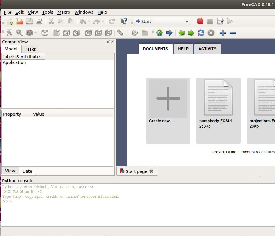
                              Starting FreeCAD gives this rather intimidating screen:

                              freecad_cold.jpg

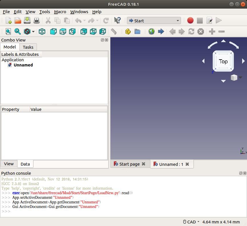
                              Clicking on '+ Create New' gets a little further, but still no coconut:

                              freecad_start.jpg

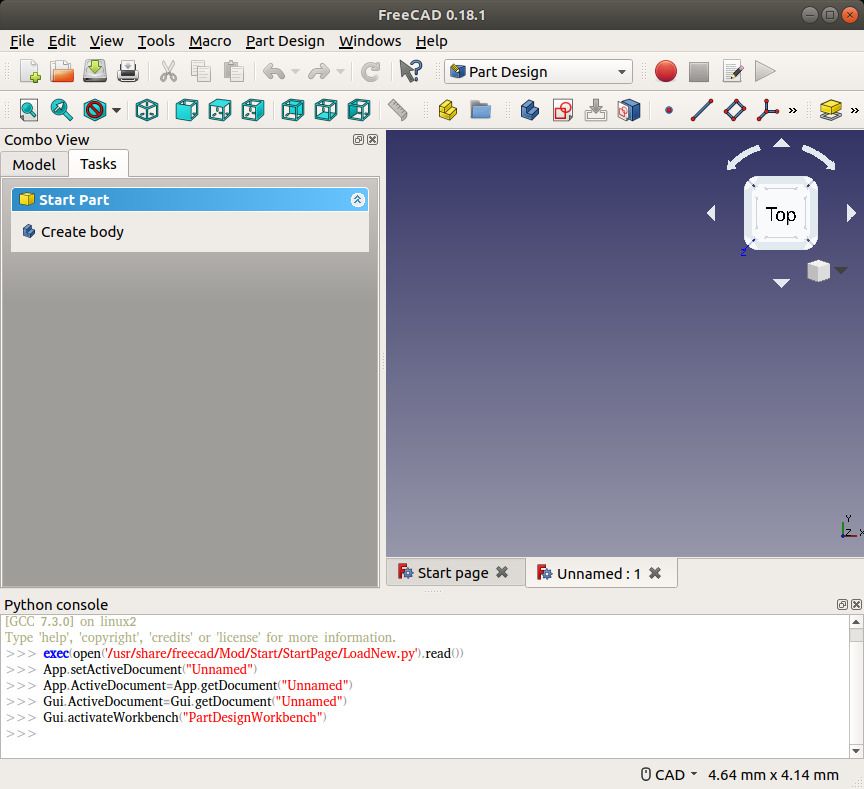
                              So, Click on the start button, and choose 'Part Design'

                              freecadcreatebody.jpg

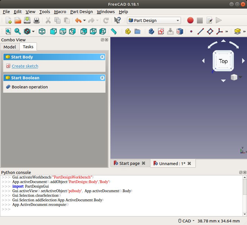
                              The tasks panel lists 'Start Part Create Body', click which produces 'Create Sketch':

                              freecadcreatesketch.jpg

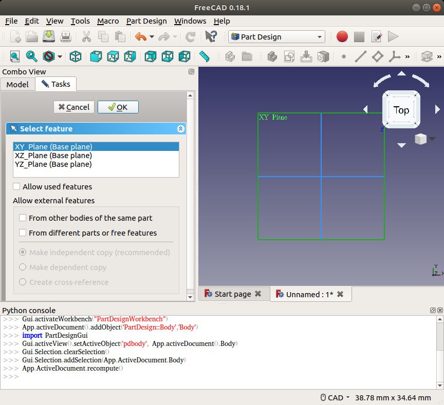
                              Clicking 'Create Sketch' asks another question, which plane should we draw on:

                              freecad_setplane.jpg

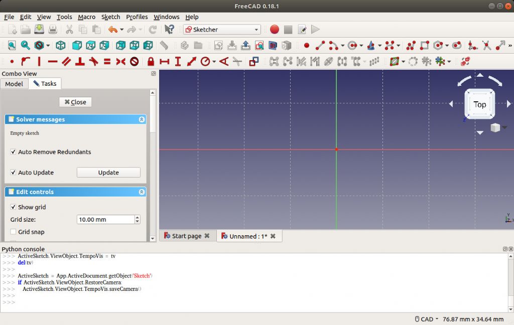
                              Choosing one of the planes opens the sketch editor, and lots of new buttons. Those with red dots and white lines are drawing tools ( the white circle with two red dots draws radius circles ). The Red buttons set constraints, forcing lines to be Vertical, Horizontal, or of a particular dimensioned length or angle etc. Hovering over buttons with the mouse for a second or two pops up a a description

                              freecademptysketch.jpg

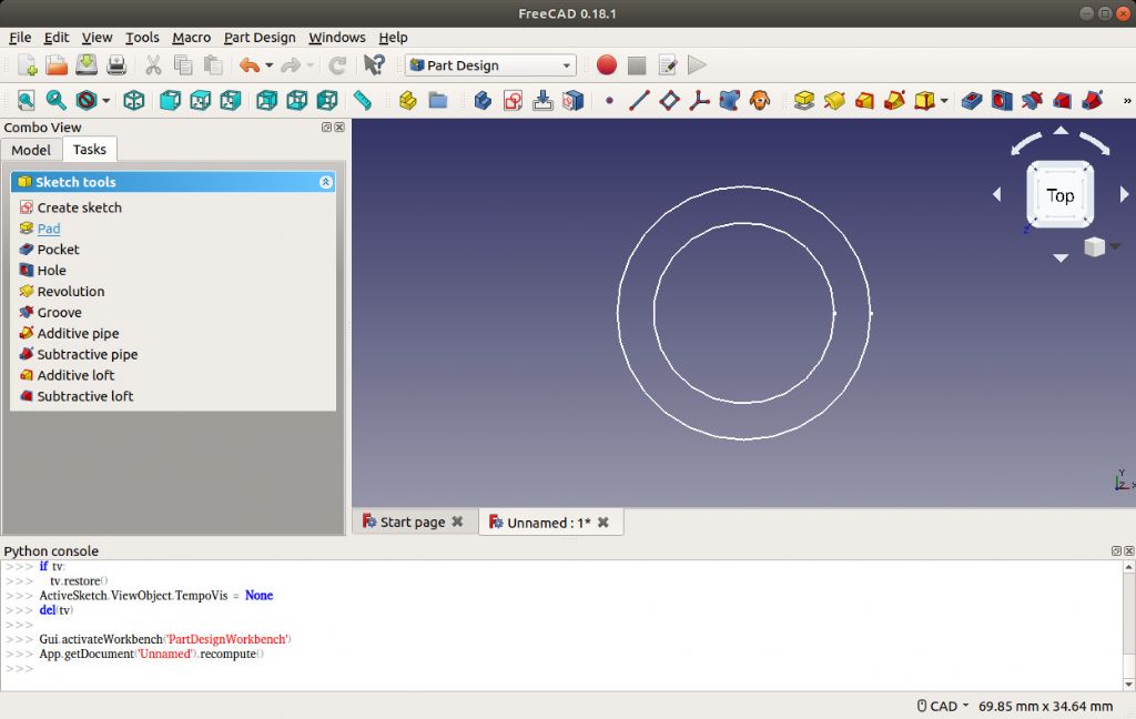
                              I used the editor to draw two circles

                              freecad_twocircles.jpg

                              Closing the editor gives a new list of Tasks:

                              freecad_padtask.jpg

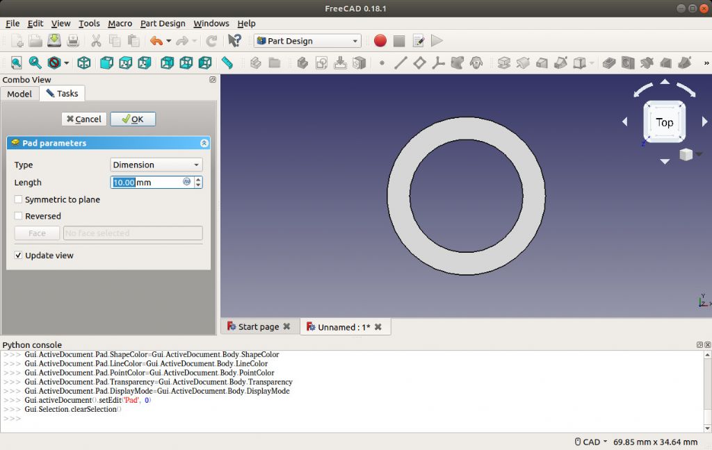
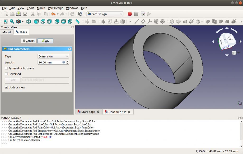
                              Clicking 'Pad' allows the area between the two circles to be extruded as a 3D cylinder. Length, your choice:

                              freecad_pad.jpg

                              The new object can be viewed from any angle:

                              freecadpadrotated.jpg

                              More in next post:

                              Dave

                              #412785
                              SillyOldDuffer
                              Moderator
                                @sillyoldduffer

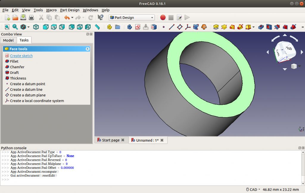
                                Clicking on the top face of the cylinder selects it:

                                freecadselectface.jpg

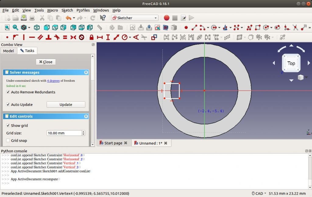
                                One of the Tasks available is another 'Create Sketch'. Clicking it opens the editor, this time working on the top of the cylinder where I've drawn a square, half on half off:

                                freecaddrawsquare.jpg

                                As an aside, note FreeCAD is complaining 'Under constrained sketch with 4 degrees of freedom'. This is because the object I've created has no constraints. I didn't set a specific radius on either circle, or put any dimensions on the square. Although it looks OK, FreeCAD knows it's dodgy. For rough work, this may not matter much, but it's not a good idea to leave objects imperfectly defined. In a complex model it can cause peculiar behaviours that baffle the user!

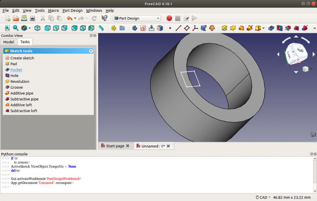
                                Closing the editor, opens up another list of tasks:

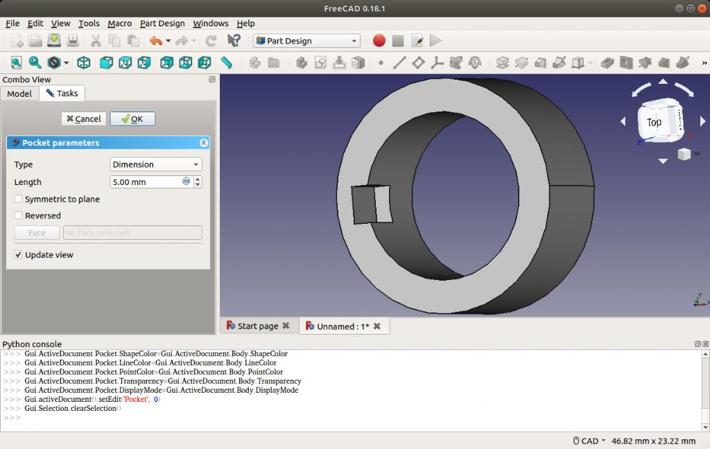
                                freecad_pocket.jpg

                                Choosing 'pocket' lets me cut a keyway inside the cylinder, I've left it halfway (dimensioned 5mm deep), but changing type to 'Through All', would create an end-to-end slot:

                                freecadpaddview.jpg

                                Most 3D CAD packages work like this. A sketch produces a solid object, which is modified by more sketches that add or remove material. Sketches can be extruded along a path to create objects like coil springs.. Common operations like holes, threaded holes and chamfers etc can be done without sketching. The package can probably draw common common objects like gears by specifying the number of teeth and diameter required.

                                The learning problem is getting started, how to produce objects that don't break the laws of geometry, how to apply draw and sketches, and how to use a few hundred buttons that make life easy once you know how they work! In the case of FreeCAD, 'getting started' is a tad convoluted because you have to do some non-obvious setting up. Once mastered though, it's the same every time, and takes much longer to describe than do.

                                Hope that helps!

                                Dave

                                #412792
                                An Other
                                Participant
                                  @another21905

                                  Maybe not relevant to the thread, but I found the following info on available CAD systems for linux users which may be useful, since the question of which CAD app to use frequently comes up in this forum.

                                  **LINK**

                                  #412813
                                  Michael Gilligan
                                  Participant
                                    @michaelgilligan61133
                                    Posted by SillyOldDuffer on 05/06/2019 17:36:35:

                                    Choosing 'pocket' lets me cut a keyway inside the cylinder, I've left it halfway (dimensioned 5mm deep), but changing type to 'Through All', would create an end-to-end slot:

                                    freecadpaddview.jpg

                                    The learning problem is getting started, how to produce objects that don't break the laws of geometry …

                                    .

                                    Nice demonstration, Dave … and it highlights one 'feature' of CAD that can catch-out the unwary: That half length keyway is very easy to draw, but would be tricky to machine.

                                    MichaelG.

                                    #412816
                                    JasonB
                                    Moderator
                                      @jasonb
                                      Posted by Michael Gilligan on 05/06/2019 20:18:09:


                                      Nice demonstration, Dave … and it highlights one 'feature' of CAD that can catch-out the unwary: That half length keyway is very easy to draw, but would be tricky to machine.

                                      MichaelG.

                                      Would the same not apply if you drew the part with pencil and paper?

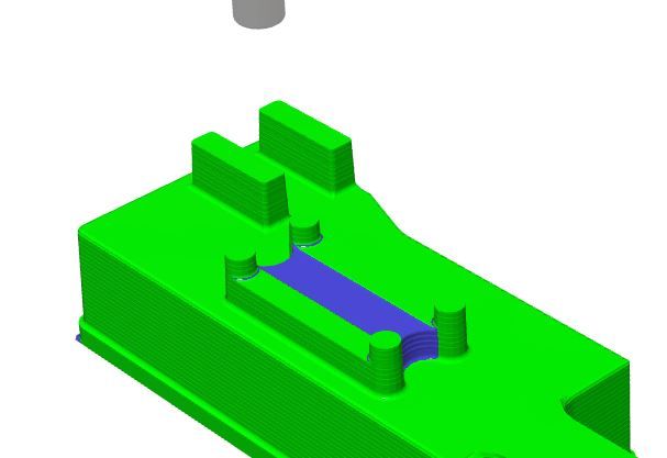
                                      On the other hand if you also have CAM you can run a simulation and that will help to show up what you can't machine. I was creating some tool paths about 1/2hr ago and the cad left some metal shaded in another colour where my cutter could not reach. Still at least with CAD it was a simple couple of clicks to adjust the two features so the tool could pass between or I could just have easily selected a smaller dia tool.

                                      tool wont fit.jpg

                                      Edited By JasonB on 05/06/2019 20:30:08

                                      Edited By JasonB on 05/06/2019 20:35:05

                                      #412817
                                      Michael Gilligan
                                      Participant
                                        @michaelgilligan61133
                                        Posted by JasonB on 05/06/2019 20:25:09:

                                        Would the same not apply if you drew the part with pencil and paper?

                                        .

                                        Well yes, of course you could draw something by hand that was unsuitable for manufacture … but I think the pace and convenience of CAD makes such errors 'easier'.

                                        I was careful to use the word 'and' not the word 'but' … i.e. I was making a positive comment about Dave's tutorial.

                                        MichaelG.

                                        #412818
                                        Nigel Graham 2
                                        Participant
                                          @nigelgraham2

                                          Dave-

                                          I am intrigued – why does FreeCAD show that programme code at the bottom of the screen? Is it something to do with creating NC control files?

                                          I once saw something like your example, at work, but its equivalent pocket had 1mm corner radii and was on a ledge deep inside an object resembling inside, the interior of a die-cast stepped pulley. Not sure how the draughtsman thought it would be milled – I don't think you can obtain 2mm slot-drills 100mm long!

                                          #412820
                                          Anonymous
                                            Posted by Nigel Graham 2 on 05/06/2019 20:50:16:

                                            I am intrigued – why does FreeCAD show that programme code at the bottom of the screen? Is it something to do with creating NC control files?

                                            I've never used FreeCAD but the "code" is nothing to do with CNC. It's simply a representation of the Python function calls the CAD program is using.

                                            Andrew

                                            Edited By Andrew Johnston on 05/06/2019 21:03:14

                                            #412822
                                            Michael Gilligan
                                            Participant
                                              @michaelgilligan61133
                                              Posted by Michael Gilligan on 05/06/2019 20:40:18:

                                              Well yes, of course you could draw something by hand that was unsuitable for manufacture …

                                              .

                                              Just as an aside … A true story:

                                              My dad got a new job, as 'technician' for a University department.

                                              One of the clever academics asked him to make an item 'to drawing' and his drawing was a Penrose triangle.

                                              Dad took it all with a straight face and, next day, duly presented the prankster with a beautifully constructed item, made [flat, of course] from wire.

                                              MichaelG.

                                              .

                                              https://en.m.wikipedia.org/wiki/Penrose_triangle


                                              Edited By Michael Gilligan on 05/06/2019 21:11:31

                                              #412826
                                              SillyOldDuffer
                                              Moderator
                                                @sillyoldduffer
                                                Posted by Michael Gilligan on 05/06/2019 20:40:18:

                                                Posted by JasonB on 05/06/2019 20:25:09:

                                                Would the same not apply if you drew the part with pencil and paper?

                                                .

                                                Well yes, of course you could draw something by hand that was unsuitable for manufacture … but I think the pace and convenience of CAD makes such errors 'easier'.

                                                I was careful to use the word 'and' not the word 'but' … i.e. I was making a positive comment about Dave's tutorial.

                                                MichaelG.

                                                Michael makes a good point, CAD packages won't save a bad designer from doing silly things. Good design, however it's done, is skilled work. On the other hand the 3D representation did make it easier to spot that hard to make flat bottomed slot.

                                                Now I'm going to tell a whopper and claim I always planned to have the item 3D printed from GCode:

                                                blush

                                                gcode.jpg

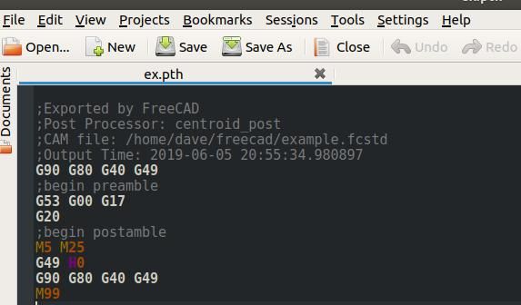
                                                I produced the G-code from FreeCAD's 'Path' Workbench. Pretty sure it's rubbish because I didn't set anything up first! You're supposed to define tools and stuff before pressing buttons at random and there are lots of options hinting at milling, engraving, contouring etc. As I don't understand any of it, only a lucky guess would have produced meaningful GCode. But, in theory, I could have FreeCAD outputting the instructions needed to make the object by subtraction (machining), or addition (3D printing).

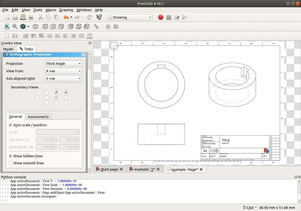
                                                2D drawings are generated from the Drawing Workbench.

                                                freecaddrawing.jpg

                                                Not trying a hard-sell. Although I think FreeCAD (version 0.18) is the best Linux 3D CAD, and it does most of the basics, it's a good few years behind the commercial products. I often use it for checking out and thinking about simple parts, switching to Fusion360 for anything complicated.

                                                Dave

                                                #412828
                                                SillyOldDuffer
                                                Moderator
                                                  @sillyoldduffer
                                                  Posted by Andrew Johnston on 05/06/2019 21:02:48:

                                                  Posted by Nigel Graham 2 on 05/06/2019 20:50:16:

                                                  I am intrigued – why does FreeCAD show that programme code at the bottom of the screen? Is it something to do with creating NC control files?

                                                  I've never used FreeCAD but the "code" is nothing to do with CNC. It's simply a representation of the Python function calls the CAD program is using.

                                                  Andrew

                                                  Edited By Andrew Johnston on 05/06/2019 21:03:14

                                                  That's right. The Python console can be turned off. Mostly it just shows what the program is doing behind the scenes. It's possible for the user to type modelling commands into the console as well, but I've never experimented with it.

                                                  Dave

                                                  #412865
                                                  Kiwi Bloke
                                                  Participant
                                                    @kiwibloke62605

                                                    SOD – Brilliant! Thank you! Now you've shown where the front door is, I'd better be brave and venture in to FreeCAD. Ever thought of writing a bit more on the subject for MEW?

                                                    FreeCAD appeals to me because this is a Linux-only household, but the fact that it's free (and runs on any platform) should surely appeal to many of our colleagues, some of whom appear to be as tight as myself…

                                                    You say FreeCAD is a few years behind some commercial products; is this a bad thing, is it significantly handicapped? Most of us use manual machines, conceptually designed, or even dating from, the turn of the last century. We are used to old-fashioned stuff – ourselves, partners and friends included…

                                                    #412882
                                                    SillyOldDuffer
                                                    Moderator
                                                      @sillyoldduffer
                                                      Posted by Kiwi Bloke 1 on 06/06/2019 07:15:50:

                                                      Ever thought of writing a bit more on the subject for MEW?

                                                      FreeCAD appeals to me because this is a Linux-only household, but the fact that it's free (and runs on any platform) should surely appeal to many of our colleagues, some of whom appear to be as tight as myself…

                                                      You say FreeCAD is a few years behind some commercial products; is this a bad thing, is it significantly handicapped? Most of us use manual machines, conceptually designed, or even dating from, the turn of the last century. We are used to old-fashioned stuff – ourselves, partners and friends included…

                                                      I've thought of doing a FreeCAD article but they're hard work. I'm struggling at the moment to write one on producing photo-resist artwork for Inkscape. ( See Terrance Holland's Barclay Well Tanks of the Great War Part 49 in ME4614 20/6/2019 for a good description of etching from artwork. Also Neil Wyatt in ME4477. ) In Part 48 Terrance describe ways of making masters involving a mix of manual, photographic and computer methods. My article aims to show how most of Part 47 can be done more simply and with greater range with an appropriate software tool. For this purpose Inkscape is better than a Word Processor, MS-Paint, 2D-CAD, and 3D-CAD. All the others could have a crack at signage, but are clumsy &/or limited. Wrong tools for the job.

                                                      barclaywell.jpg

                                                      cityoftruro.jpg

                                                      90% Linux myself. It is the true faith! Not always the best software though, and I don't feel guilty about using MicroSnot.

                                                      FreeCAD suffers a little in comparison with commercial packages because Mechanical Engineering is only one of several Workbenches they have in development. FreeCAD can do things like model a ship's hull that Alibre and Fusion can't, but that's not much use to me, I'd rather all the development effort was put into Part Design. And that plethora of CAD functions to choose from on the start screen is liable to confuse newcomers.

                                                      FreeCAD's still being developed, which means that some of the web advice is out-of-date, another source of learning confusion. One or two updates have been buggy, which is off-putting if you don't upgrade regularly to get the fixed version!

                                                      FreeCAD's Part Design is good for drawing single objects. Most individual items can be modelled. What's missing at the moment is any facility to combine parts together in a realistic way. So you can draw a bush and a spindle separately, but not assemble them together. It's possible to combine them as a single new part, but that's not what's wanted. Assembly has to align the spindle part inside the bush and allow it to rotate, or slide, or both. FreeCAD doesn't do that yet.

                                                      I don't think learning FreeCAD is a dead end; I found Fusion 360 follows much the same get you started basic principles, albeit with many extra features, differences in the detail, and conveniences. From what I've read about Alibre, its basic way of working is similar too.

                                                      Dave

                                                    Viewing 25 posts - 51 through 75 (of 178 total)
                                                    • Please log in to reply to this topic. Registering is free and easy using the links on the menu at the top of this page.

                                                    Advert

                                                    Latest Replies

                                                    Viewing 25 topics - 1 through 25 (of 25 total)
                                                    Viewing 25 topics - 1 through 25 (of 25 total)

                                                    View full reply list.

                                                    Advert

                                                    Newsletter Sign-up