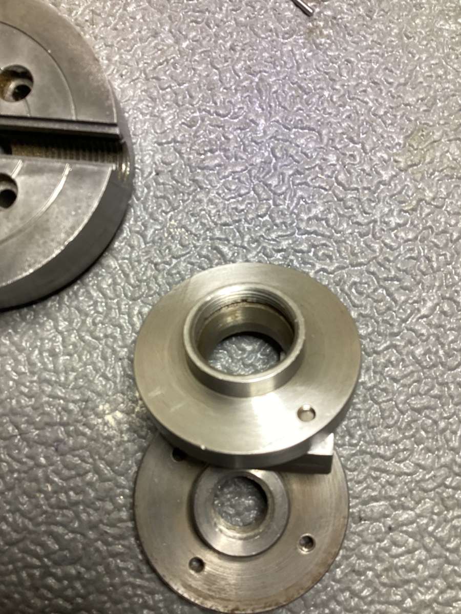
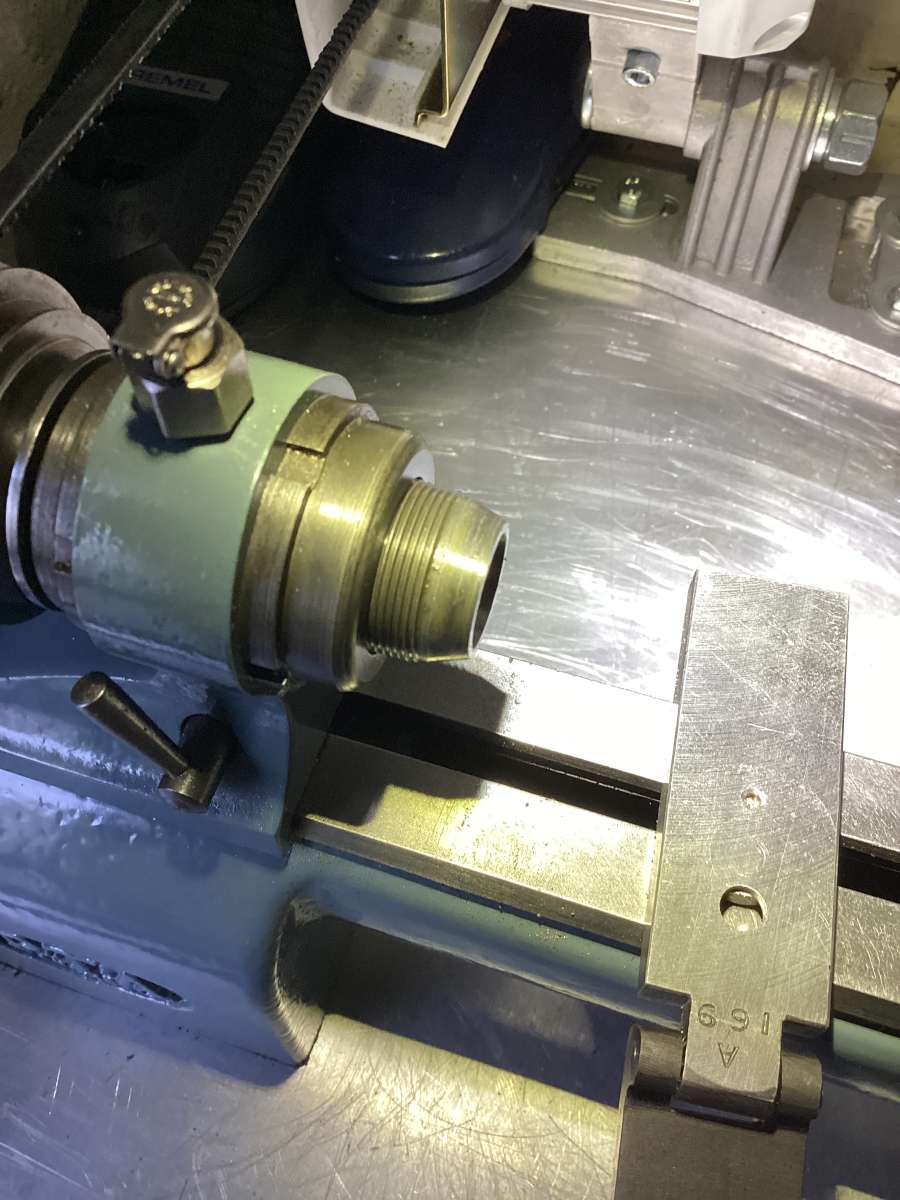
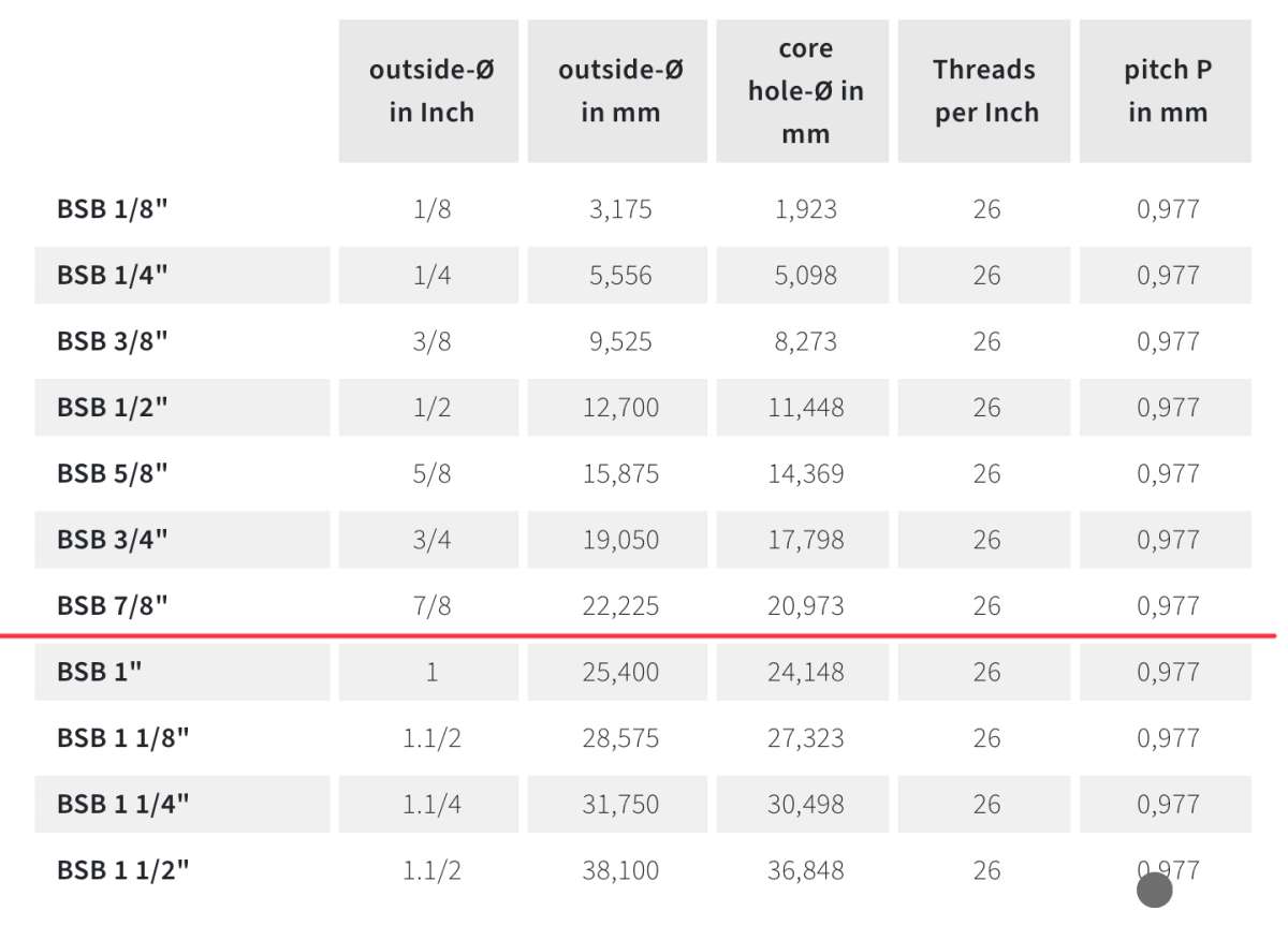
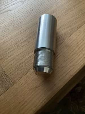
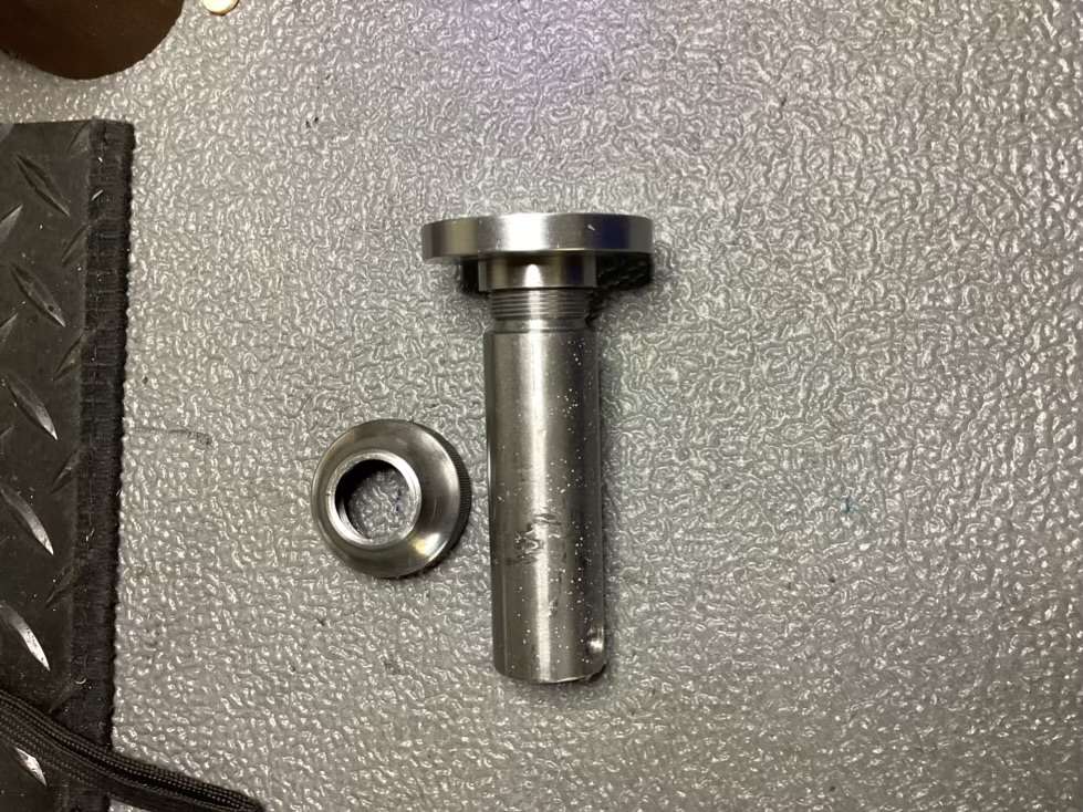
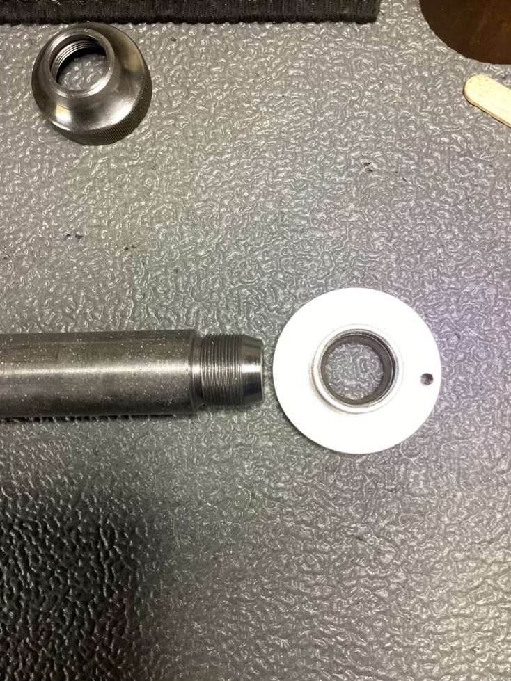
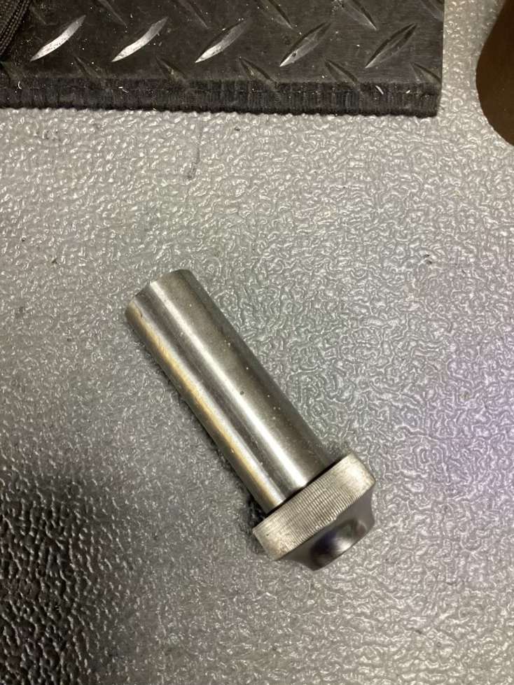
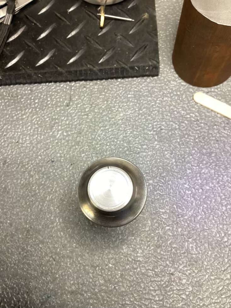
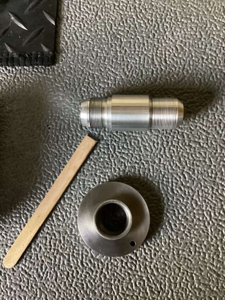
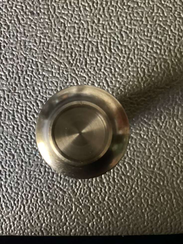
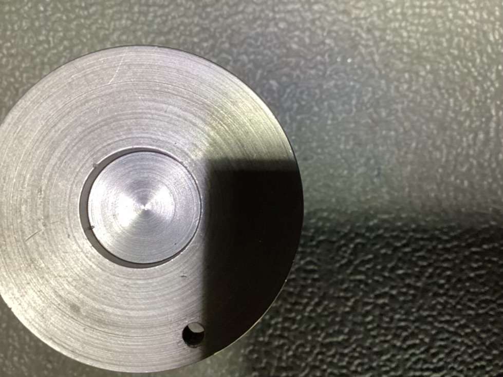
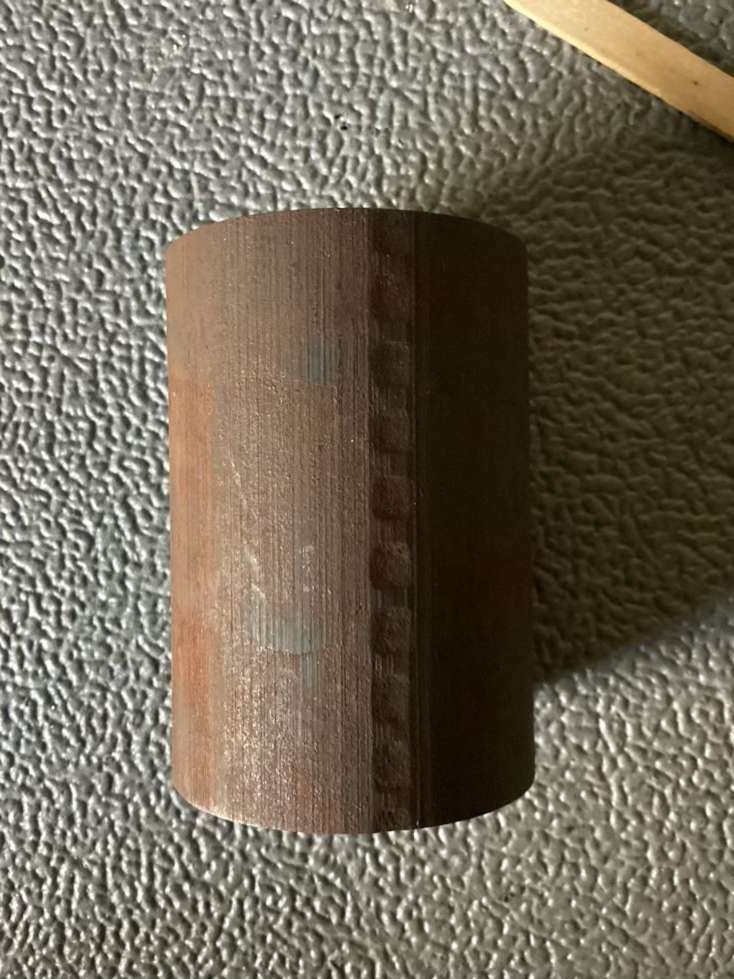
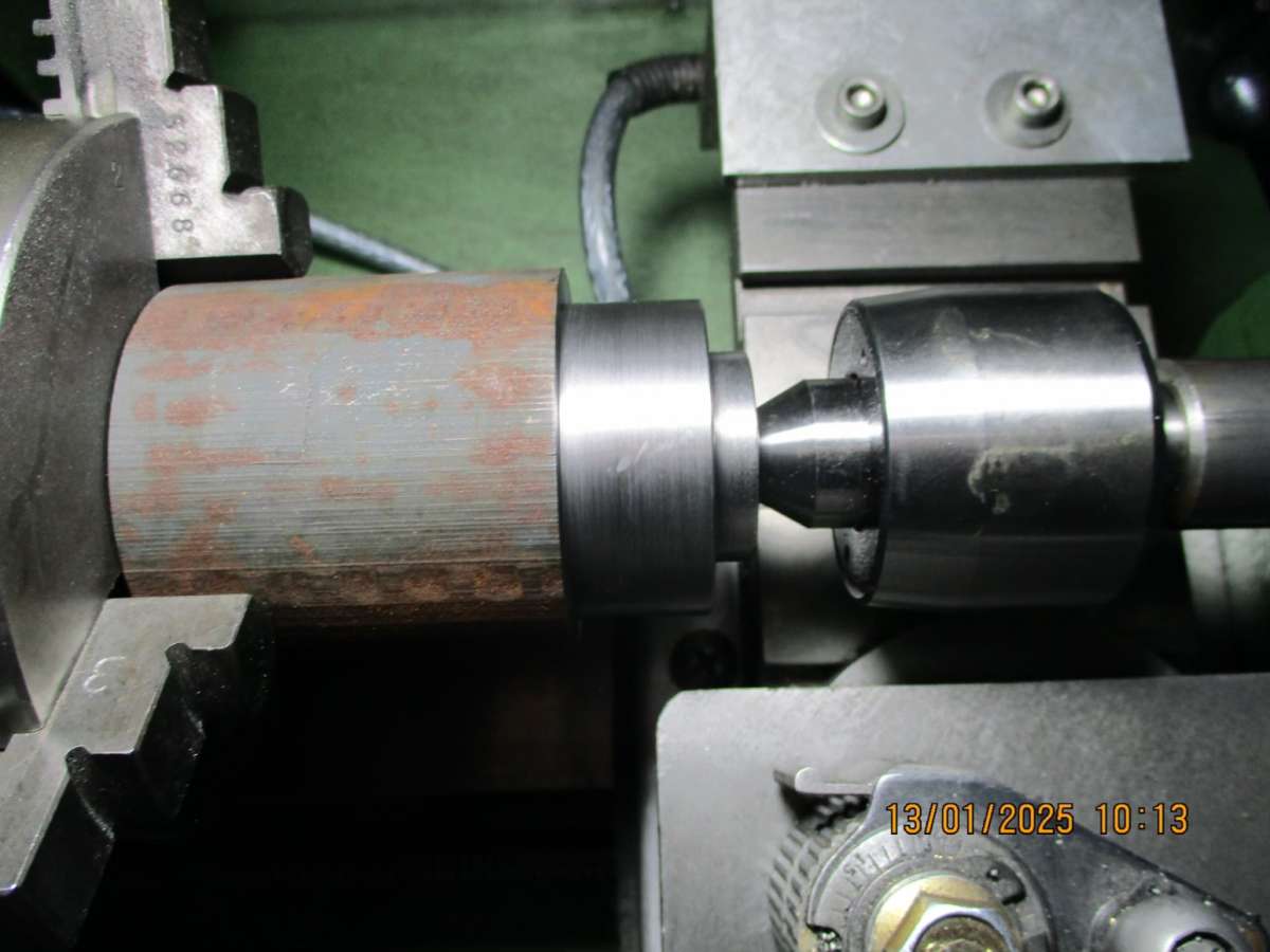
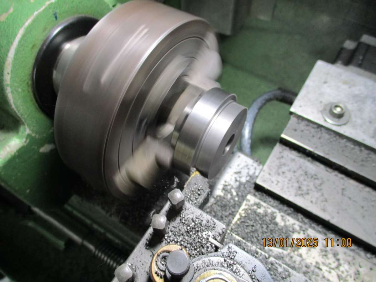
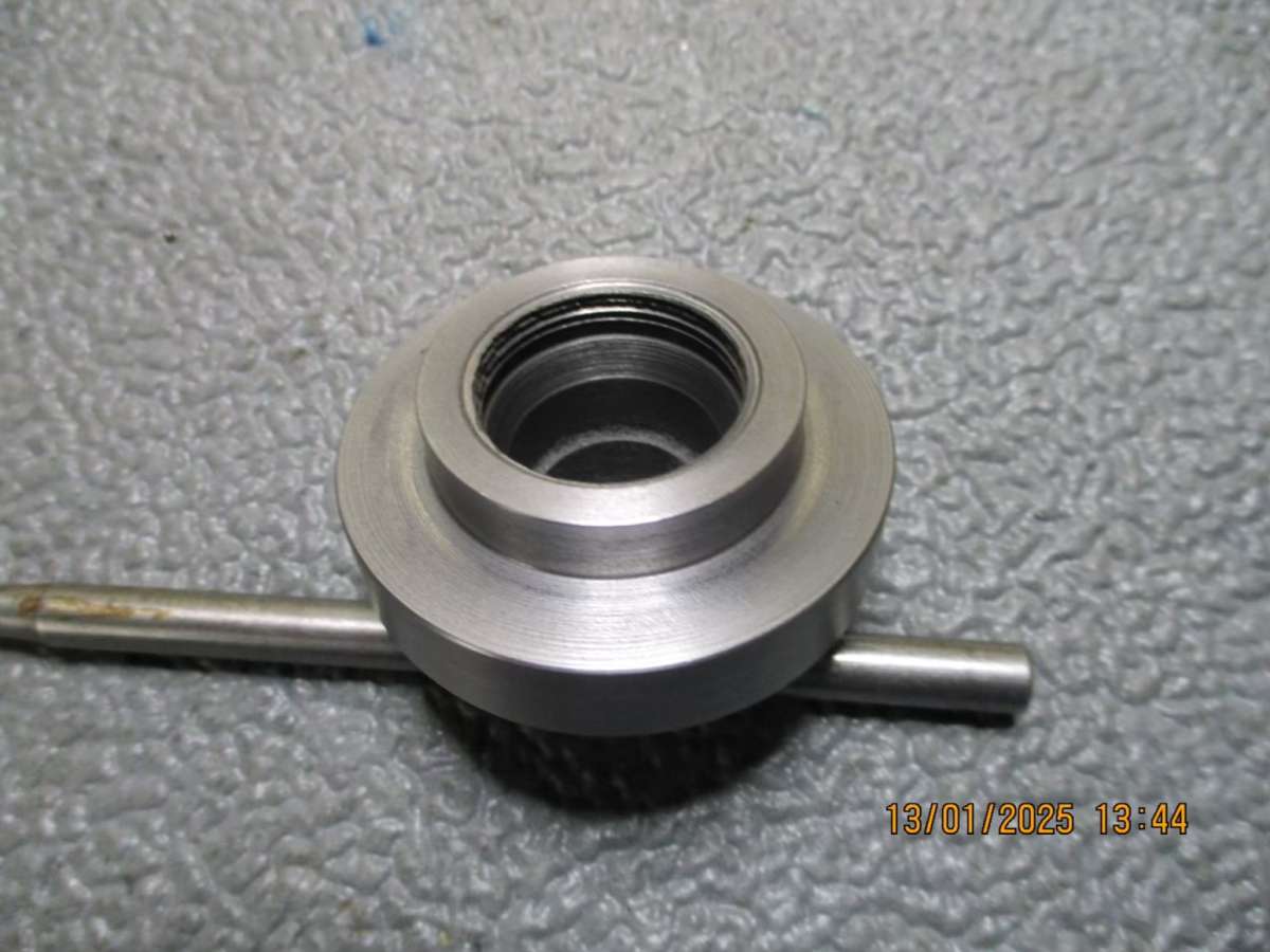
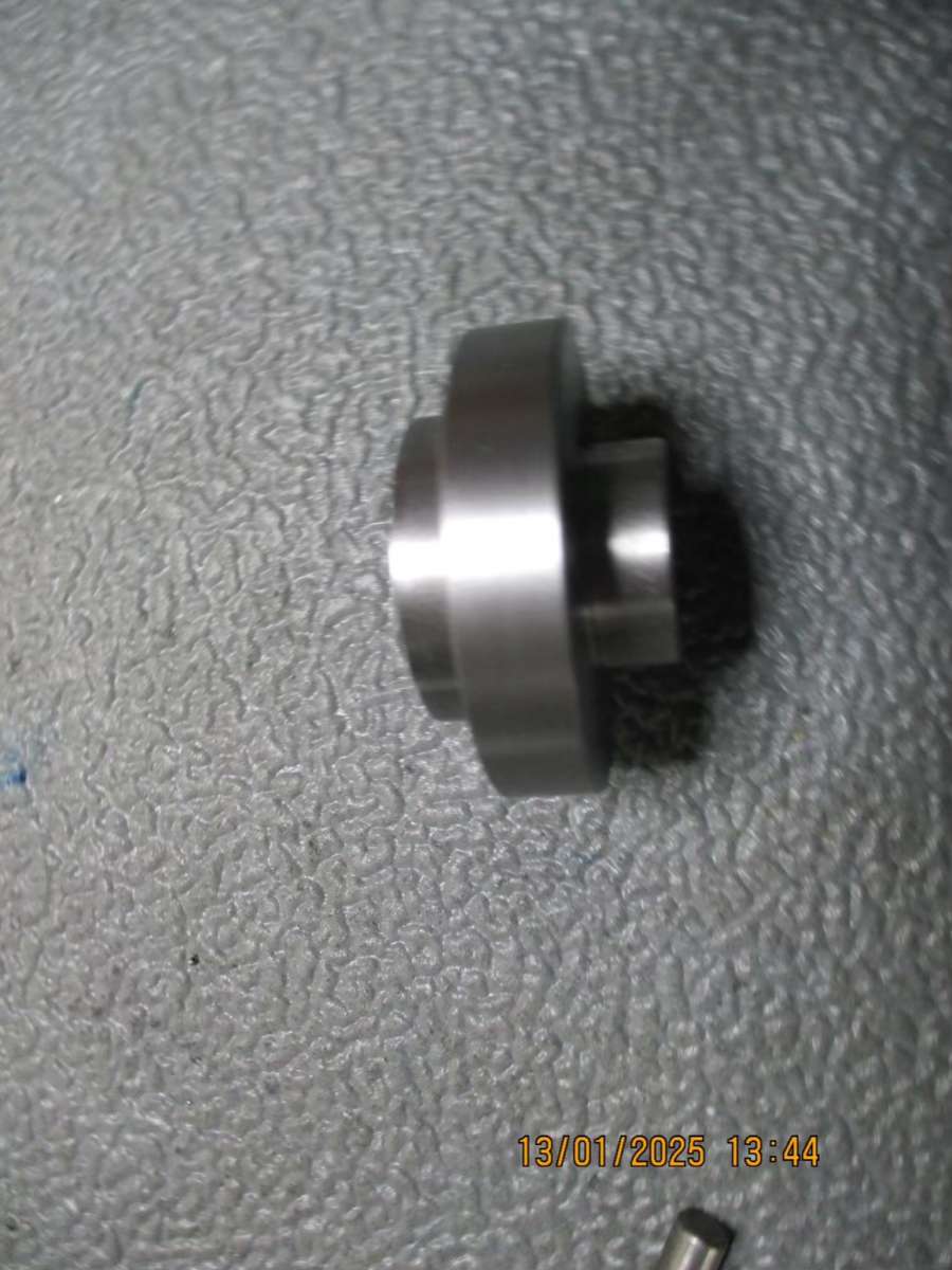
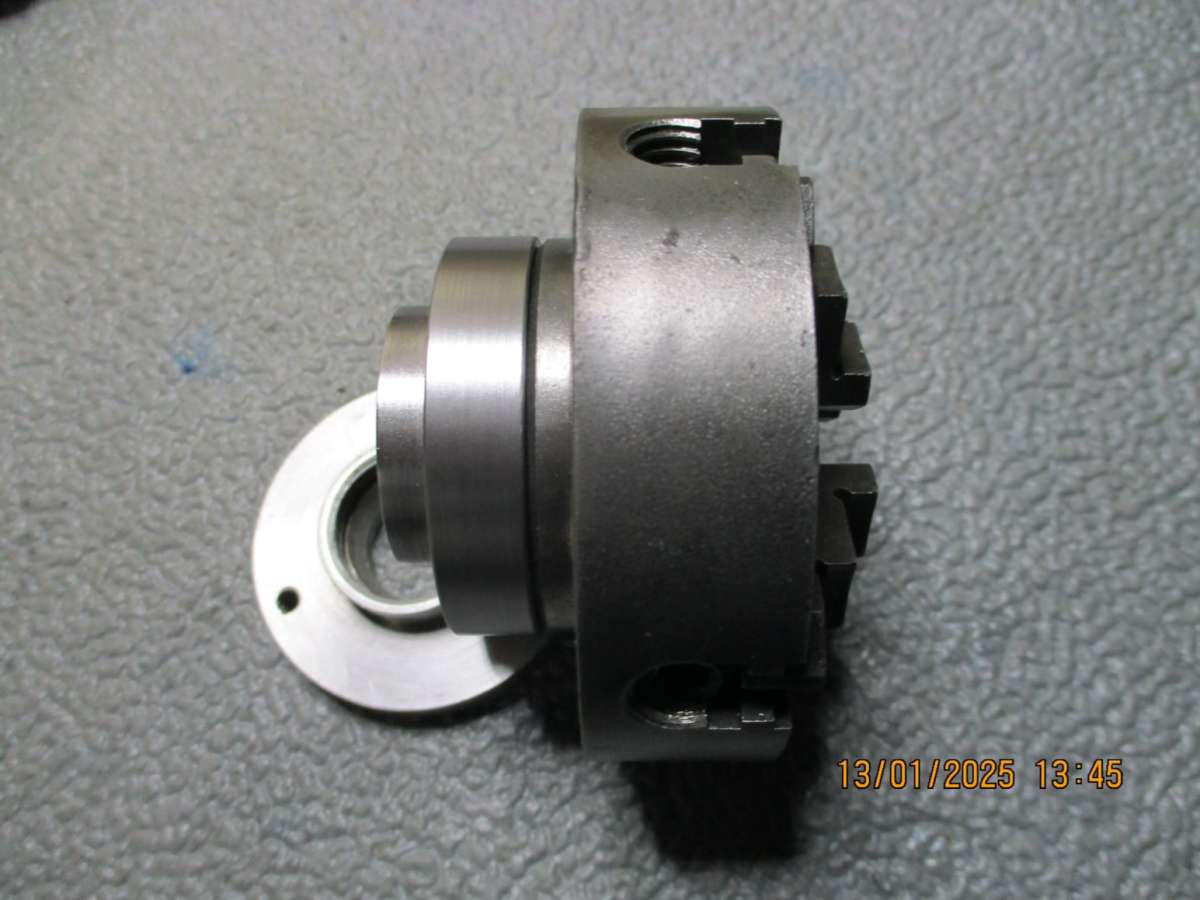
Internal thread & taper in same hole
Internal thread & taper in same hole
- This topic has 23 replies, 10 voices, and was last updated 14 January 2025 at 22:18 by
 Howard Lewis.
- Please log in to reply to this topic. Registering is free and easy using the links on the menu at the top of this page.
Latest Replies
-
- Topic
- Voices
- Last Post
-
-
Chucking Money Away!
Started by:
Chris Crew
in: The Tea Room
- 2
-
4 July 2025 at 21:24
duncan webster 1
-
New member
Started by:
nige1
in: Introduce Yourself – New members start here!
- 1
-
4 July 2025 at 20:54
nige1
-
Speed camera
1
2
3
Started by:
David George 1
in: The Tea Room
- 23
-
4 July 2025 at 20:39
Plasma
-
Amadeal AMABL210E Review – Any Requests?
1
2
Started by:
JasonB
in: Model Engineer & Workshop
- 16
-
4 July 2025 at 20:24
Robert Atkinson 2
-
The Perpetual Demise of the Model engineer
Started by:
Luker
in: Model engineering club news
- 13
-
4 July 2025 at 17:06
JasonB
-
Colchester Chipmaster Clutch question
Started by:
Peter_H
in: Manual machine tools
- 3
-
4 July 2025 at 16:44
notlobgp14
-
Advice moving 3x machines
Started by:
choochoo_baloo
in: Workshop Techniques
- 5
-
4 July 2025 at 15:46
Bazyle
-
Firth Valve Gear
Started by:
Andy Stopford
in: Traction engines
- 10
-
4 July 2025 at 14:42
duncan webster 1
-
What Did You Do Today 2025
1
2
…
6
7
Started by:
JasonB
in: The Tea Room
- 33
-
4 July 2025 at 14:28
Nick Wheeler
-
A Persistent Scam
Started by:
Chris Crew
in: The Tea Room
- 5
-
4 July 2025 at 14:23
Speedy Builder5
-
ML10 backgear
Started by:
alexander1
in: Manual machine tools
- 3
-
4 July 2025 at 13:34
Bazyle
-
Boxford lathe & vertical mill VFD conversion help with start stop
Started by:
Andrew Schofield
in: Beginners questions
- 2
-
4 July 2025 at 10:38
Andrew Schofield
-
Hemmingway rotary broaching kit
Started by:
YouraT
in: Workshop Tools and Tooling
- 4
-
4 July 2025 at 09:02
jimmy b
-
Bentley BR2 Rotary Aero Engine
Started by:
notlobgp14
in: Miscellaneous models
- 3
-
4 July 2025 at 06:54
JasonB
-
Collet closer identification.
Started by:
vic newey
in: Workshop Tools and Tooling
- 10
-
3 July 2025 at 22:36
richlb
-
Starrett micrometer.
Started by:
Graeme Seed
in: Workshop Tools and Tooling
- 5
-
3 July 2025 at 21:25
peak4
-
A grasshopper of unknown vintage
Started by:
mikemunson
in: Stationary engines
- 3
-
3 July 2025 at 20:21
Charles Lamont
-
New (but well aged) member
Started by:
mikemunson
in: Introduce Yourself – New members start here!
- 4
-
3 July 2025 at 19:55
noel shelley
-
New member from Lancashire
Started by:
mannyroad
in: Introduce Yourself – New members start here!
- 7
-
3 July 2025 at 19:14
notlobgp14
-
Bearing boxes for ball race
Started by:
Paul McDonough
in: Beginners questions
- 10
-
3 July 2025 at 18:35
Paul McDonough
-
Twin Engineering’s heavy mill/drill quill removal
Started by:
Martin of Wick
in: Manual machine tools
- 10
-
3 July 2025 at 17:53
David George 1
-
Loctite axles
Started by:
steve2250
in: General Questions
- 5
-
3 July 2025 at 12:22
parovoz
-
Comments (constructive) on the New Forum Software
1
2
…
34
35
Started by:
JasonB
in: New Forum Software questions, comments and Test Threads
- 134
-
3 July 2025 at 10:25
Emgee
-
Grimsby & Cleethorpes MES on the BBC
Started by:
Chris Crew
in: The Tea Room
- 1
-
3 July 2025 at 08:51
Chris Crew
-
Injectors
Started by:
pansy123
in: General Questions
- 6
-
3 July 2025 at 07:05
Dave Wootton
-
Chucking Money Away!


