Install & commission of a Chester Cub 630 (Warco GH750)

Advert

Install & commission of a Chester Cub 630 (Warco GH750)

Home Forums Manual machine tools Install & commission of a Chester Cub 630 (Warco GH750)

Viewing 19 posts - 51 through 69 (of 69 total)
  • Author
    Posts
  • #552686
    John P
    Participant
      @johnp77052

      As far as the change wheels go your best bet would be to inquire at Warco or Chester,i would
      be surprised if they had these as a stock item in their stores these machines are not that
      common especially from Warco ,they only sold these machines for a couple of years.I had
      a problem with a pair of the head stock gears around about 2009 and they had to order some
      gears from China back then ,if you look through handbook you have at page 4 of 29 you
      will probably see the notes that i made on the page.

      The change wheels are 2.5 module at 20 deg PA and it is unlikely that you will find another
      machine that uses these sizes at only 10mm wide.

      The real problem if you have to make them is if the Chester variant of this machine is the
      same as the Warco is the Six spline hub used for the mounting , see the photo in the
      last post i made on the 26/06/2021 10:40:54 .

      The machine has not got a Norton gearbox ,the feed change gearbox has 9 speeds ,the
      diagram here shows the output for 1 revolution input as you may see in position 3 and III
      is 3.5 revolutions output.

      The calculation using the change wheels , outputs the size in mm = pitch for 1 revolution
      of the chuck.

      From your posting…
      "I got the change wheels off, and I've got a 26, 27, 28, 30, and a 36, so I'll need to acquire the
      rest at some point. Again, not a major issue. Odd thing is that doesn't seem to be a listed
      combination for anything on the front panel charts!"

      If you look at the 3rd panel down on the change wheel chart 8 columns along mm per rev
      you will see the listing 2,4,8 and above A36 B27 D28 E30 ,these are the only screw cutting
      pitches that you can do with the change wheels that you have.

      You can not change to imperial thread cutting as Howard suggests by fitting a 127 tooth and
      complementary gear ,on this machine it just will not work at the lead screw end of the
      gearbox when changing the drive from the feed screw shaft to the lead screw ,the change
      in position engages a 45 tooth to 21 tooth gear which ruins any calculation.The machine
      however with the full change wheel set can do a fair number of imperial pitches with
      a very small error on a 10 tpi pitch the error on 10 inches of thread is
      only 0.00027 inches.

      An article written by me was in MEW 257 to obtain a true metric to imperial conversion
      and required 4 gears the results were limited to 10 and 8 tpi the only sizes that i
      really needed.
      The photo here shows the gears.

      Some other articles on this machine have appeared in MEW :
      Cnc conversion MEW 207 to 212
      Large fixed steady and boring bar MEW 207 to 208
      Milling attachment for milling lead screws /worms MEW 241 to 243.

      John

      warco gear box.jpg

      Workshop28.jpg

      Advert
      #552724
      Calum
      Participant
        @calumgalleitch87969

        Thank you John for those notes – those MEW references are especially helpful, as they are all of interest.

        The gears are indeed on a spline, but the spline itself – at least on the gears I removed – is a separate piece and simply fits on a geared shaft on my lathe, so with any luck no need to remake it and I can just bore a hole and keyway. I'm also havering about an electronic leadscrew to learn something of the electronics etc before considering a full CNC conversion down the road, so maybe I can live permanently without the extra gears.

        #552732
        Calum
        Participant
          @calumgalleitch87969
          Posted by Calum Galleitch on 05/07/2021 14:59:47:
          geared shaft

          Keyed shaft, that should read 🙄

          #552841
          John P
          Participant
            @johnp77052

            H Calum,

            Previously i had written ,
            If you look at the 3rd panel down on the change wheel chart 8 columns along mm per rev
            you will see the listing 2,4,8 and above A36 B27 D28 E30 .

            On reflection it may be possible to do all of the metric pitches from 0.5 through
            to 9 mm as you have the 28 ,30 and 36 tooth gear the B gear in those columns
            that show as A,B and C , the B is the idler providing you can bridge the gap between
            The A and C gears with one of the remaining gears it will work.

            My machine is similar in that the splined hubs revolve on the plain shafts and as
            such could be replaced as in your situation where that you do not have a full set
            of change wheels, you will have to remake or modify the hub that is the A gear
            stud this links the 45 tooth 2.25 module gear that provides the drive from
            the lathe spindle via the 2 17 tooth gears . The 45 tooth gear
            is also mounted on this same splined hub as the A gear.
            The drive out from the machine here is at 1/4 spindle speed and i expect
            that is why the change wheel gears are 2.5 module as the speed drops
            so the load goes up in the same proportion. The bonus here is the
            change wheels are very quiet in operation as even at top spindle speed
            at 2000 rpm the change wheels are at only 500 rpm.

            It would still be worth trying to get the missing change wheels to avoid
            a lot of extra work.

            It is well to note the outer diameter of the splined hubs are the reference diameter
            for the gears to run on ,so if you were to make the internal splines in the
            gear blanks this diameter needs to be concentric with the gear teeth.

            I faced a similar problem when i made some of the gears for the 127 gear
            metric /imperial conversion , i made a fabricated spline as seen here in
            the photo the inner part is milled and the hub can be used as a gauge ,an
            outer ring is fitted over and loctited in place with a keeper in place
            to hold the parts until the loctite sets ,then 6 m3 screws are drilled and
            tapped into each spline segment before parting off ,the gear is pre-made.
            Providing care is taken to get the parts sized properly and the inner ring
            bored and turned at the same setting a perfectly good fitting splined gear
            will result , a little tedious to do but probably easier than cutting an
            internal spline .

            The layout of the gearbox and the change wheels is a little odd compared
            with most lathes ,i suspect that there are many more combinations of
            pitches that are not listed, with the permutations of gears that
            increment 1 tooth at a time , i think that the 45 tooth gear is the largest
            that can fit on the machine without fouling the mounting studs but 18
            tooth is just possible and still fitting on the splined hub , if you had
            all the numbers from 18 to 45 and that could be fitted that would be
            a lot extra pitches i expect some would be of no use, but just using
            a pocket calculator and juggling the positions of some gears can see
            pitch increments of less than 0.002 ".

            It looks a tidy machine that you have there ,i think you will be well
            pleased with it.

            John

            hub 1.jpg

            hub 2.jpg

            #552883
            Calum
            Participant
              @calumgalleitch87969

              Yes, I see what you mean about metric threads, John – I'll have to do a little programming to work through all the combinations and see what works. With any luck, that might well do me – I don't anticipate doing much threading in general and I intend to remain as metric as possible.

              #553911
              Calum
              Participant
                @calumgalleitch87969

                Well, today's job was changing the oil in the headstock, thread gearbox, and apron. I chopped the top off an empty beercan, punched a hole in the bottom, installed a plastic electrical gland and inserted a bit of PVC tubing in it and tightened it up. Next time I'd use a larger ID hose, but it worked well enough. I drained 3-4 litres of oil from the headstock, and while it could probably have been a cleaner job there were no disasters.

                I did consider mopping or siphoning the rest of the headstock out and cleaning out the sump, but since the lathe has been so little used I am assuming there is very little there to find. The oil that drained off certainly looked clean enough.

                When I came to drain the threading gearbox and apron I got rather a surprise: both were completely dry! The drain plugs were good and tight, so possibly they've never been filled, or a previous attempt at maintenance was curtailed, who knows. The apron sight glass did look like it had had oil in it; I wasn't so sure about the threading gearbox. While I was doing the oily work, I took the opportunity to clean the heavy (factory?) grease off the change wheels to make them a bit more pleasant to work with.

                With all that done, the lathe is actually ready to run! I don't have a full tooling complement yet, but a set of HSS cutters turned up from Warco the other day, and I bought a load of EN1A "bar ends" off the auction site to get the scrap pile started. So here, complete with accidental background music are (almost) the first chips off the lathe.

                #554501
                Calum
                Participant
                  @calumgalleitch87969

                  So, today's query. Not urgent but will definitely need to work out a fix at some point: the (D1-5) camlock pins are stuck absolutely solid. I balked at the idea of paying £14 for a proper 11mm key, so instead did the sensible thing of spending all day making one, as well as buying a drilling vice to complete the project – make your own things, they said, save money, they said…

                  Anyway, the camlock sockets are the normal type, with v-indicators at three o'clock and six o'clock, and the socket arrow pointing somewhere in between them. All six sockets look like they're in the right place, I don't think there's any funny business going on like being tightened the wrong way, etc. It's either rust or the chuck was installed by the incredible hulk. I had a go with a helper bar, and bent the tommy bar, which is 8mm EN1A rod.

                  What should my next steps be? I assume a bit of WD40 won't do any harm, but otherwise I'm at a bit of a loss, and google doesn't seem to know much about it either.

                  #554505
                  Roger Best
                  Participant
                    @rogerbest89007

                    Oil and wait is always good, also which is the correct direction to loosen them?

                    Well done so far – it looks mint.

                    #554510
                    Calum
                    Participant
                      @calumgalleitch87969

                      I have the two V indicators similar to this pic (not my lathe):

                      screenshot from 2021-07-17 22-25-04.jpg

                      I don't have the I indicator at the top, but the socket itself is pointing between the Vs so I am fairly sure I should be turning anti-clockwise to vertical:

                      screenshot from 2021-07-17 22-25-27.jpg

                      I've got WD40 on hand, though I've seen suggestions that more powerful alternatives might be better – but I've no idea what they might be!

                      #554652
                      John P
                      Participant
                        @johnp77052

                        Hi Callum,

                        Here is the D15 socket on my Warco lathe ,the only makings here are
                        as you can see ,when the two marks align the stud is unlocked.
                        The photo that you have shown is a more normal representation
                        for a D mount arrangement the two > < indicate the position
                        of the mark on the spindle flange providing the socket line is within the
                        two marks the chuck is locked.
                        I would guess that your chuck has been tightened for some time
                        and the studs seem over time to grip quite strongly ,as you have said
                        from the open position at the 12 o'clock the socket is rotated
                        clockwise to stop at about 5 o'clock in the locked position.
                        Is there any reason that they should be rusty ,is there any rust showing
                        around the chuck or anywhere else.
                        The key shown here has a lever shaft of 10 mm dia and a bit tougher
                        than mild steel.

                        John

                        warco d15.jpg

                        warco  d15.jpg

                        #554680
                        Calum
                        Participant
                          @calumgalleitch87969

                          Thanks John, that does make sense. I don't have any particular reason to suspect rust ingress – the likely explanation is simply that the chuck has probably never been removed since it was mounted ~20 years ago. That's interesting what you say about the connection getting tighter over time. Certainly sounds a better plan than having it shake itself loose!

                          I'll give it the WD40 and see if I can apply a bit more welly to it. I'm a bit wary about going full hulk on things like this because I can put a bit more weight into it than the designers may have had in mind!

                          #556857
                          Calum
                          Participant
                            @calumgalleitch87969

                            Surprisingly difficult to find an 11mm chuck key, but I did find a 7/16" key which needed just a hair ground off to fit. And, with a good bit of force, and an extremely alarming bang the camlocks came loose. I got the chuck off, and like everything else, it looks suspiciously like the original factory grease.

                            I mounted the four jaw up just to see that it fitted, after all that, and it does – just. The jaws will hold quite a large workpiece without protruding beyond the chuck anyway but without doubt one could accidentally do a great deal of damage if they tried!

                            #589513
                            Calum
                            Participant
                              @calumgalleitch87969

                              For various reasons I've been meaning to take the cross-slide off and have a look, so though I would add a note about my experience here. Removing it is simple enough:

                              • Compound off
                              • Unscrew the mounting bolts for the leadscrew
                              • Remove the leadscrew
                              • Remove the two machine screws holding the cross-slide nut in place
                              • Undo the plate at the front covering the gib adjuster
                              • Unscrew and remove the gib strip
                              • Slide the cross slide towards you – you have to lift it slightly for clearance (note that the brass cross-slide lock is loose and will fall out easily if you tilt the slide when carrying it)

                              I say simple – I may be omitting one or two steps that turned out to be unnecessary!

                              img_20220312_150121210.jpg

                              The large hole at the bottom locates the compound, the slightly smaller hole above is to access the T-nuts that run in the circular T-slot to hold the compound (of which more anon). The very top hole is for oil, as are the two on the bearing surface. Then the remaining three are for the cross-slide nut.

                              The cross-slide nut itself is two blocks of brass (or bronze) pinned together with a wedge on which a grub screw in the small hole bears. This can (I have now learnt after googling!) be used to reduce backlash: tighten up one machine screw, adjust the set screw on the wedge until backlash is eliminated, then tighten up the other screw.

                              I successfully got the T-nuts out through the access hole. One of the threads is stripped so I need to make or find replacements – I have had a quick google and can't see anything that looks like a standard part, but fortunately I have a lathe(!)

                              Finally, here's a shot of the carriage without the slide for reference:

                              img_20220312_150339417.jpg

                              #591684
                              Calum
                              Participant
                                @calumgalleitch87969

                                I've been working today on my fixture plate in this thread:

                                https://www.model-engineer.co.uk/forums/postings.asp?th=177296

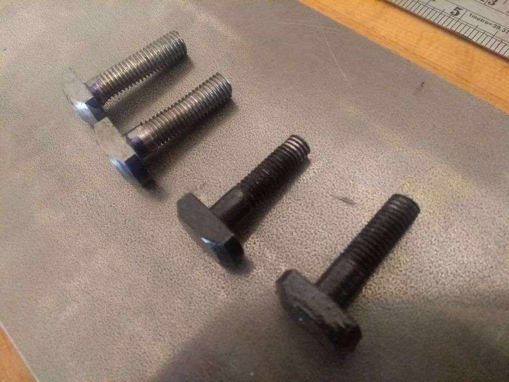
                                which I will update separately, but as I also managed to install my replacement t-nuts today, I thought I'd add a note about them. I'm not sure if the lathe came with a stripped thread or if I managed to damage it very early on, but it's always been loose enough that the nut could be tightened so that it "jumped" over the thread, so I couldn't lock one side of the compound down properly.

                                img_20220326_122344143.jpg

                                Originals in black – you can see the stripped thread! As you can see the threads are not an especially tidy job – my order of operations was not optimal. I copied the original dimensions except for making the overall length just a few mm longer. I'd like to say it was skill but it was more like sheer luck that the end result sits pretty neatly:

                                img_20220326_153600210.jpg

                                I'll add a quick sketch with dimensions just in case anyone ever finds it useful.

                                #591685
                                Calum
                                Participant
                                  @calumgalleitch87969

                                  screenshot from 2022-03-26 17-19-33.jpg

                                  The dimension across the flats is 13.5 (all in mm).

                                  The original nuts had a 30mm shank; I made mine 33mm and they fitted neatly.

                                  The only noteworthy thing about making them, perhaps, was the small taper which provides clearance to install the nut – this is an awkward angle to cut with the compound, so I swung it round the other way and ran the lathe in reverse with a tool held like a boring bar. That and a healthy workout with the file to make the flats!

                                  #593874
                                  Calum
                                  Participant
                                    @calumgalleitch87969

                                    I'd like to have a go at making gears to make up the missing changewheels that I have – I think I'll do a separate thread about them as it may be of more general interest but I'm just trying to understand the gear train of my lathe:

                                    screenshot from 2022-04-10 15-55-39.jpg

                                    Beginning with the spindle, wheels 13,17,16,18, 19 and 20 have 45, 45, 45, 68, 17 and 45 teeth, so for one turn of the spindle A will be turned 45/68*17/45 times = 1/4 which is what John P wrote last year…so far so good!

                                    Q. Where/how is the reverse in this diagram? Physically on the lathe it's somewhere round the wheels labelled 17-18 but unless the reverse mechanism is not drawn I don't see how it works.

                                    In the quickchange box, 21/22/23 mesh with 29/30/31, giving ratios of 20/40, 40/20, 30/30 which corresponds with the 1/2/3 knob. Like wise the second knob, 24/25/26 mesh with 32/33/34 giving 20/40, 42/24, 36/24 (1/2, 7/4,3/2).

                                    Finally, if the leadscrew is selected the drive is fed through wheels 36 to 28, which are 45/21.

                                    Q. Am I right in thinking the manual states it is a 4mm pitch leadscrew? Slightly alarmingly it gives "module no. or pitch" as '4 or 1/6" '. Now 4mm is close to 1/6" but it's not that close!

                                    Putting all this together, If I choose to cut a 4mm thread, I take A,B,C,D=36,27,28,30 teeth from the front chart and select 2,II (30/30, 36/24). One spindle revolution then gives:

                                    1/4 * 36/27 * 28/30 * 30/30 * 36/24 * 45/21 = 1 turn of the leadscrew, so if it is a 4mm leadscrew we've got a 4mm pitch. Phew.

                                    When the feed is selected, the 45/21 drops out and the feed rod turns.

                                    Q. What is happening at 44/45? Clearly this is where torque is being taken off the feed. Then (assuming carriage feed engaged) 48 drives 46 which drives the wheel engaging the rack? But what are 50/51/52 doing?

                                    Similar for the cross-feed I assume 47 engages 48, in turn driving 49.

                                    I'll add the manual pages for the gear list to my lathe album should anyone feel inclined to try and make sense of it!

                                    #593902
                                    John P
                                    Participant
                                      @johnp77052

                                      Posted by Calum Galleitch 10/04/2022 17:22:06

                                      I'd like to have a go at making gears to make up the missing changewheels that
                                      I have – I think I'll do a separate thread about them as it may be of more general
                                      interest but I'm just trying to understand the gear train of my lathe:

                                      Beginning with the spindle, wheels 13,17,16,18, 19 and 20 have 45, 45, 45, 68, 17
                                      and 45 teeth, so for one turn of the spindle A will be turned 45/68*17/45 times = 1/4
                                      which is what John P wrote last year…so far so good!

                                      Q. Where/how is the reverse in this diagram? Physically on the lathe it's somewhere
                                      round the wheels labelled 17-18 but unless the reverse mechanism is not drawn
                                      I don't see how it works.

                                      In the quickchange box, 21/22/23 mesh with 29/30/31, giving ratios of
                                      20/40, 40/20, 30/30 which corresponds with the 1/2/3 knob. Like wise the
                                      second knob, 24/25/26 mesh with 32/33/34 giving 20/40, 42/24, 36/24 (1/2, 7/4,3/2).

                                      Finally, if the leadscrew is selected the drive is fed through wheels 36 to 28,
                                      which are 45/21.

                                      Q. Am I right in thinking the manual states it is a 4mm pitch leadscrew?
                                      Slightly alarmingly it gives "module no. or pitch" as '4 or 1/6" '. Now 4mm is
                                      close to 1/6" but it's not that close!

                                      Putting all this together, If I choose to cut a 4mm thread,
                                      I take A,B,C,D=36,27,28,30 teeth from the front chart and
                                      select 2,II (30/30, 36/24). One spindle revolution then gives:

                                      1/4 * 36/27 * 28/30 * 30/30 * 36/24 * 45/21 = 1 turn of the
                                      leadscrew, so if it is a 4mm leadscrew we've got a 4mm pitch. Phew.

                                      When the feed is selected, the 45/21 drops out and the feed rod turns.

                                      Q. What is happening at 44/45? Clearly this is where torque is being taken
                                      off the feed. Then (assuming carriage feed engaged) 48 drives 46 which
                                      drives the wheel engaging the rack? But what are 50/51/52 doing?

                                      Similar for the cross-feed I assume 47 engages 48, in turn driving 49.

                                      I'll add the manual pages for the gear list to my lathe album should anyone
                                      feel inclined to try and make sense of it!


                                      —————————————————————————————-

                                      Hi Calum

                                      The gear chart is depicted as a diagram and as such lacks the detail
                                      needed,the reverse feed is the 16 and 17 cluster gear ,in reality
                                      the gear 13 directly meshes with gear 18 ,i think the gear 18 slides along
                                      a spline and sits in the gap between gear 16 and 17 for neutral
                                      and connects to gear 13 via 17 and 16 to 18 to reverse the rotation.
                                      It is some while since i have had the lid off so this is from memory.

                                      Gear 44 is a worm that engages with the slot on the feedscrew that drives
                                      wormwheel 45 and is the input drive to the apron.

                                      The auto feed clutch dog either drives the apron along the bed through
                                      gear 50 to 51 ,51 is connected to gear 43 which drives along the rack
                                      57 under the bedway.

                                      When the auto feed clutch is in the other position (it is quite poorly drawn)
                                      gear 48 drives gear 47 through gear 46 to gear 48 which is part of the
                                      crosslide leadscrew.
                                      There may be some differences from the 750 machine that you have and the
                                      GH 1000 i have as if you look at the photo's the handwheels are in different
                                      positions ,this may not affect the operation but the gears may not be the same.

                                      John

                                      Edited By John P on 10/04/2022 22:50:03

                                      Edited By John P on 10/04/2022 22:52:48

                                      #593967
                                      John P
                                      Participant
                                        @johnp77052

                                        Posted by John P 10/04/2022 22:49:12
                                        When the auto feed clutch is in the other position (it is quite poorly drawn)
                                        gear 48 drives gear 47 through gear 46 to gear 48 which is part of the
                                        crosslide leadscrew.

                                        ——————————————————

                                        This should have been,

                                        When the auto feed clutch is in the other position (it is quite poorly drawn)
                                        gear 48 drives gear 47 to gear 46 to gear 49 which is part of the
                                        crosslide leadscrew.

                                        49 is not listed as a gear but is the crosslide leadscrew at the top of
                                        the page 6 of the manual and is part of item 40.

                                        John

                                        #593973
                                        Calum
                                        Participant
                                          @calumgalleitch87969

                                          Thanks John, that certainly all makes sense and I'll just have to do a little testing to make sure it matches up with what we expect!

                                          I didn't realise until I'd posted that the next page of the manual lists the full transmission ratios for the various systems, so that will help in tracing what goes where.

                                        Viewing 19 posts - 51 through 69 (of 69 total)
                                        • Please log in to reply to this topic. Registering is free and easy using the links on the menu at the top of this page.

                                        Advert

                                        Latest Replies

                                        Home Forums Manual machine tools Topics

                                        Viewing 25 topics - 1 through 25 (of 25 total)
                                        Viewing 25 topics - 1 through 25 (of 25 total)

                                        View full reply list.

                                        Advert

                                        Newsletter Sign-up