Inserted cross slide feed nuts

Advert

Inserted cross slide feed nuts

Home Forums Manual machine tools Inserted cross slide feed nuts

Viewing 25 posts - 51 through 75 (of 79 total)
  • Author
    Posts
  • #482421
    Andy Carlson
    Participant
      @andycarlson18141
      Posted by Nigel Graham 2 on 26/06/2020 23:38:53:

      For a 1/8-inch lead-screw, I work out 12.5 tpi being feasible with a 32T change-wheel. Pair it with a 50T wheel. (Or 64 / 50 with 1/2 compounding.)

      Note you might need keep the half-nuts engaged the whole time unless the lathe has a thread-dial indicator.

      I have a small Denbigh horizontal mill, not yet back in service, and one of the screws on that is 6TPI. I forget which but I think it is the long-travel lead-screw!

      8 / 40 x 25 x 50 / 20 .= 12.5

      Probably impossible to set up like that but that's as far as my brain wants to go just now.

      Advert
      #482452
      Nigel Graham 2
      Participant
        @nigelgraham2

        Andy – that lathe sounds similar to my EW, with that change-wheel range and permanently-engaged lead-screw; 1/8 inch lead on the EW.

        I once cut a non-standard metric thread on it, and working out the gear train to give minimum pitch error took some doing!

        I did those sums by multiplying 8/12.5 to the lowest multiple of 8 for integers and a feasible pinion size; hence 32/50.

        #482545
        old mart
        Participant
          @oldmart

          I must have missed the Howard Lewis post mentioning the Myford leadscrew pitch. There is your answer, Myford spares are far easier to get hold of than any other make, and the modifying them to fit is by far the easiest option.

          #482722
          Andy Carlson
          Participant
            @andycarlson18141
            Posted by old mart on 27/06/2020 16:31:30:

            I must have missed the Howard Lewis post mentioning the Myford leadscrew pitch. There is your answer, Myford spares are far easier to get hold of than any other make, and the modifying them to fit is by far the easiest option.

            Now if anyone makes feed screws for the ML1-4 then that would really save me some effort. I haven't found any though.

            I suspect the nut design is… err… unique… to Faircut so I'm getting started on making one to see if I can do it.

            #482726
            Pete Rimmer
            Participant
              @peterimmer30576
              Posted by Andy Carlson on 27/06/2020 00:03:23:

              @David: thanks – good to see someone who has actually done it. I was thinking along similar lines. Making one tap seems less hassle than making three.

              Did you screw cut a square thread or a pointy one?

              Looks like you heat treated your tap – did you just harden it or did you harden and temper?

              12.5 TPI… an interesting idea thanks but I probably lack the gears to do that. The Faircut has 2 off 20T and then goes up in 5T steps to 65T. I suspect this is the full original set. It would also mean making the screw and nut at the same time.

              FYI the Faircut has a permanently engaged leadscrew..

              Cutting a feed screw length thread brings some additional challenges that I'd rather save until another occasion.

              For now I'm going to go with 12 TPI and see if I can actually make a nut that works. At least the gearing is straightforward.

              Andy, if there's a particular gear you need for your setup to get you 12.5TPI I could probably make it for you.

              #482738
              Andy Carlson
              Participant
                @andycarlson18141

                Andy, if there's a particular gear you need for your setup to get you 12.5TPI I could probably make it for you.

                Thanks for the offer Pete but at the moment I'm going with 12.

                #483009
                Andy Carlson
                Participant
                  @andycarlson18141

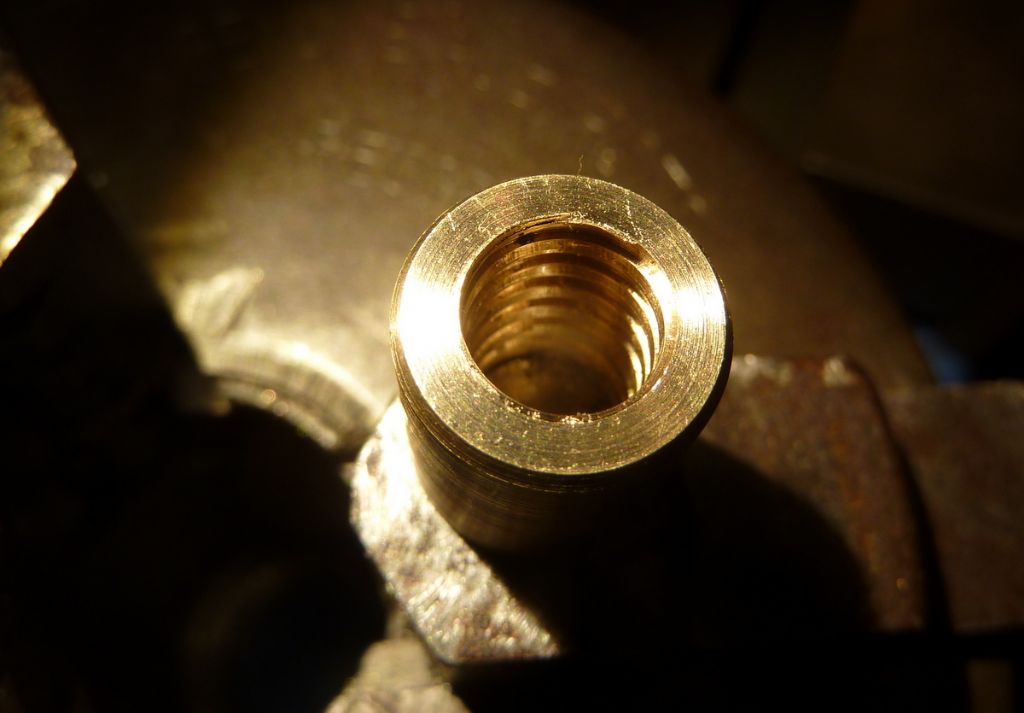
                  Well that went better than expected…

                  p1070492.jpg

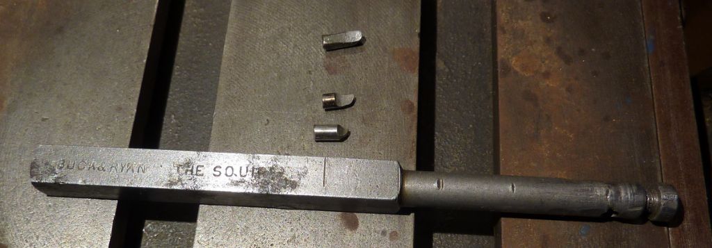
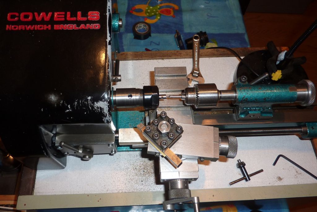
                  A long way from the finished article but the approach shows promise. I had a think and remembered 'The Squire' which came with the lathe when I bought it. I wondered if he could help…

                  p1070482.jpg

                  I dug out some cheapo chinese 3mm HSS milling cutters and ground up a couple of inserts. Not easy and they both ended up a bit under the correct width but they are not too bad.

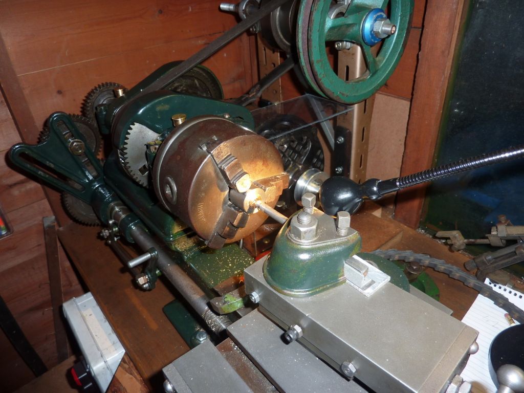
                  The job on the lathe…

                  p1070485.jpg

                  I've made a bush to hold the new cross feed nut in the 3 jaw for drilling, boring and threading. I could have used the 4 jaw but didn't want to squash the job, plus if I'm making several then this way will be less hassle in the long term.

                  The idea was to swap from the short insert to the longer one part way through. The shank on 'The Squire' is 6.9mm and the minor thread diameter about 7.4mm, which means I can only have half the 'stick out' that I need to fully cut the thread.

                  I stopped the job after bottoming out the shorter insert. I've now decided that changing inserts mid-job was a bad idea and I need to make a 'mini squire' that will allow the full thread depth of 'stick out'. I also need to make a proper mandrel handle but turning the countershaft by hand is definitely the way to go.

                  #483011
                  David George 1
                  Participant
                    @davidgeorge1

                    Hi Andy I screw cut the thread with a square bit the same size as the thread. The tap was cut to same pitch with same gears and after milling with a ball end slot drill to give the cutting clearance I hardened it and then tempered it back to dark straw on the cutting part and let the shank down to blue. the internal thread cutter was just ground from a piece of HSS.

                    20190520_080901.jpg

                    if you need any help just drop me a message.

                    David

                    #483014
                    Andy Carlson
                    Participant
                      @andycarlson18141
                      Posted by David George 1 on 29/06/2020 22:58:20:

                      Cheers David. I'm still waiting for a the materials to do the 'proper job' (including silver steel for a tap) but practicing with what I have is teaching me a lot. I was aiming for the correct width on the tools… but found it was all too easy to end up under size. Still… I have another 9 chinese 3mm end mills still available for upcycling. They arent much use for milling.

                      #483588
                      Andy Carlson
                      Participant
                        @andycarlson18141

                        This is definitely a learning experience…

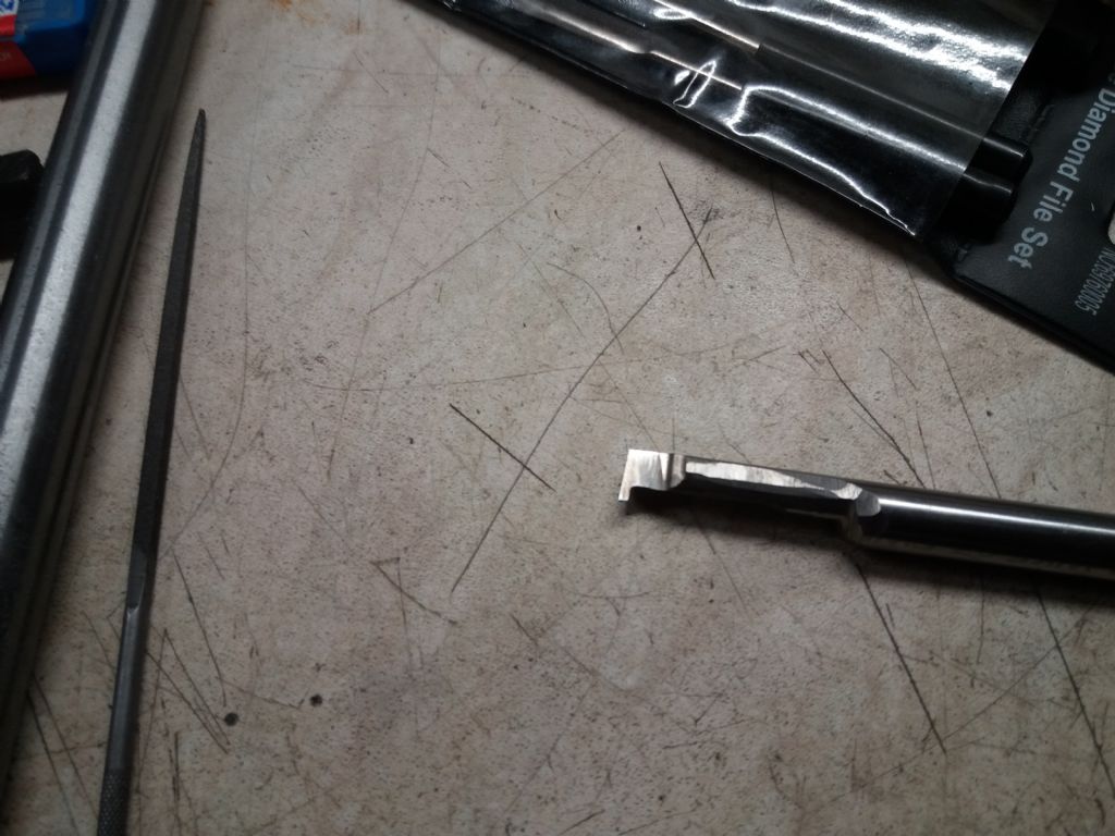
                        Got myself a little more 'tooled up' yesterday by making a mini 'Squire' from 6mm silver steel on the Cowells. This fits into the Arc Euro holder that is intended for their HSS boring tool.

                        p1070495.jpg

                        I also made a handle for the countershaft (which is effective but looks awful so no photos!) and a couple of little gauges from 15 thou brass, one to check the thread width and the other to check the depth.

                        Tonight I had another go at the same cross slide feed nut and proved to myself that I couldn't 'pick up' the thread. No matter… this is a test… I pressed on to the point where the depth gauge just about fitted and the smaller bar and countershaft handle both proved their worth. Then on the final cut the cutting insert came loose from the bar (doh… should have tightened the screw again once it was held in the toolpost).

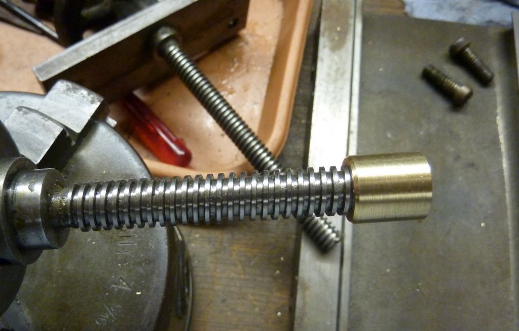
                        I'd 'lost' the thread again but it was near enough to try. It just about goes on to a not too worn thread but is very stiff. Making a finishing tap should help (still waiting for the silver steel). I also discovered that I'd made a howling error. Can you spot it?

                        p1070498.jpg

                        #483686
                        old mart
                        Participant
                          @oldmart

                          I can't say what your howling error is, but hold fire on getting the thread in the nut any looser. The most used part of the leadscrew will be much looser on the nut, assuming that it can be screwed right on to find out.

                          #483709
                          Paul Fallert
                          Participant
                            @paulfallert28101

                            Andy Carlson

                            You might try making an aluminium nut and hacksawing it in half longitudinally. Apply one half to the screw and you will see where the cutter needs any "minor" correction.

                            Being able to SEE how your thread fits the screw is a big help. I was surprised to see the mismatch on the first one. Yet, a quick test would have me believe that it was "good", but the contact area when cut open was very slight and would have become sloppy very quickly.

                            I made three before I did brass and the brass nut was a really good fit. Another dodge, assuming the screw is worth keeping, is to make a nut that best fits the worn area of the screw and use it to lap the less worn area of the screw. This avoids the loose/tight problem, but only if we are talking about slight wear of the screw. One "safer" lapping compound brand is Timesaver, which comes in grades and stops lapping after a certain point. Of course, use a very fine grade, frequent testing and meticulous removal of the lapping compound. When you have the threading process working, make a few extra brass nuts. It takes very little time passing before you forget how to set-up and cut a proper left hand Acme thread.

                            Paul

                            #483717
                            Keith Long
                            Participant
                              @keithlong89920
                              Posted by Andy Carlson on 02/07/2020 22:22:07:

                              This is definitely a learning experience…

                              I also discovered that I'd made a howling error. Can you spot it?

                              p1070498.jpg

                              Possibly getting right and left hand mixed up?

                              #483745
                              Andy Carlson
                              Participant
                                @andycarlson18141
                                Posted by Keith Long on 03/07/2020 17:04:09:

                                Possibly getting right and left hand mixed up?

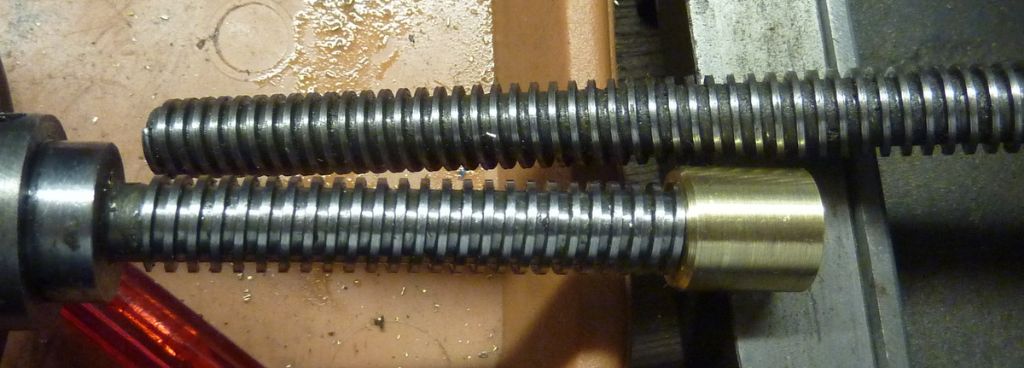
                                Spot on!

                                p1070501.jpg

                                The cross slide feed screw is at the top.

                                A pretty fundamental incorrect assumption that I've had for so long that I didn't question it…. Oops!

                                No great drama since this is a test and the tailstock feed screw allowed me to do at least some checking for fit.

                                I'm glad now that I'm doing this one step at a time – could have been expensive if I'd gone out and paid for the wrong threaded rod.

                                Incidentally I also thought I'd try checking it on a more worn feed screw. I took the screw out of the 'spare' tailstock… and found that Faircut had changed to 8TPI in the tailstock by the time that one was made.

                                Still waiting for silver steel…

                                #483751
                                Andy Carlson
                                Participant
                                  @andycarlson18141
                                  Posted by Paul Fallert on 03/07/2020 16:43:01:You might try making an aluminium nut and hacksawing it in half longitudinally. Apply one half to the screw and you will see where the cutter needs any "minor" correction.l

                                  Thanks Paul. Sounds like a good tip. I might do that with the 'wrong un' – like I said, it's a learning experience.

                                  I'm not sure I can achieve minor corrections though – I really need a better setup for less 'agricultural' grinding jobs. I'm still looking for the 'putting metal back on' wheel too. I'm sure it's around here somewhere.

                                  #483911
                                  old mart
                                  Participant
                                    @oldmart

                                    Normal lathe design is for the cross slide leadscrew to have a left hand thread. You turn the wheel clockwise to cut deeper.

                                    #483928
                                    Paul Fallert
                                    Participant
                                      @paulfallert28101

                                      Andy

                                      I only had a (worn-out) lathe and some hand tools and bits. Stuff that any self-respecting model-engineer would have binned. So, I made a L-shaped mini-boring-threading-"bar" to internally thread that 3/8" dia thread. I did not know that you cannot easily do such a small internal thread, so I naively proceeded. Because there was only one Acme shaped tooth, my shaping was by a tiny triangle file and pocket stone. This boring/threading tool was silver steel. When the shape of the thread was wrong, I just ground a little more here and there and made another attempt . My point (no pun), is that filing and grinding this single point was very little time. The difficulty was patience. The advantages were the diameter of the bore was under top slide depth control, not re-grinding a tap. Starting over is quick, just re-heat and re-bend and quench-harden. You fit the tool to a visible section of the screw, not disassembled. To make a tap, you have to make a single-point tool AND then a tap. The angle of the thread is adjustable via the tool-post. Not so easy to adjust a tap. The depth of the bore is within the capability of a small-dia round-boring-threading-tool close to the edge of the top-slide. Very little tool extension/flex. [If I were to do this today, I would know to make a holder for the internal-threading-tool, just a 1/2" x 1/2" x 3" rectangular bar, with a hole in the end to closely fit the thread tool and a set screw to tighten and easily adjust the tool angle. Also, I now have a crank-handle on the back end of the spindle to hand-turn the spindle with absolute total control and no crashes. This is supposed to be relaxing, not a factory]. Harold Hall featured this tool-holder in several articles and his books.

                                      Paul

                                      #483934
                                      Andy Carlson
                                      Participant
                                        @andycarlson18141
                                        Posted by old mart on 04/07/2020 14:30:50:

                                        Normal lathe design is for the cross slide leadscrew to have a left hand thread. You turn the wheel clockwise to cut deeper.

                                        That's what I thought until Thursday night.

                                        The Faircut handles work in the expected way – you turn the handle clockwise and the slide moves away from you.

                                        It depends on the design of the cross slide though – on the Faircut the handle moves with the cross slide and runs in a nut which is inserted into the saddle, so effectively it works like a normal nut and bolt so it's a right handed thread. The compound is the same. The tailstock is a LH thread because the nut is in the barrel.

                                        On my Unimat SL the handle is mounted on the saddle and the 'nut' is on the cross slide (if you can even call it a cross slide on the Unimat).. so it's a left handed feed screw thread.

                                        #483936
                                        Andy Carlson
                                        Participant
                                          @andycarlson18141
                                          Posted by Paul Fallert on 04/07/2020 15:43:03:

                                          Paul

                                          Cheers Paul. You are right, using a silver steel cutting tool would allow me to be more precise in forming the tool shape. I've been using HSS because I generally assume that HSS is what one uses for cutting tools but we've seen where assumptions get you. I don't think I have any 3mm silver steel just now though… 1.5mm, 6mm and 17mm and I'm waiting for 10mm to make the tap and a counterbore for another job.

                                          My lathe is in a very tight space in the shed so a handle on the back end of the spindle would be pretty awkward. Having one on the big pulley works well though and once the vee belt is off it's really easy to turn. I did make a nut for the back end of my Cowells spindle and use a socket and ratchet on that. I completely agree that this is the best way to do thread cutting. Not sure 'relaxing' is a word I'd use though.

                                          #484158
                                          Andy Carlson
                                          Participant
                                            @andycarlson18141

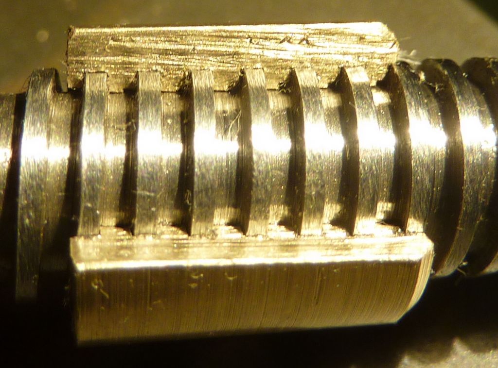
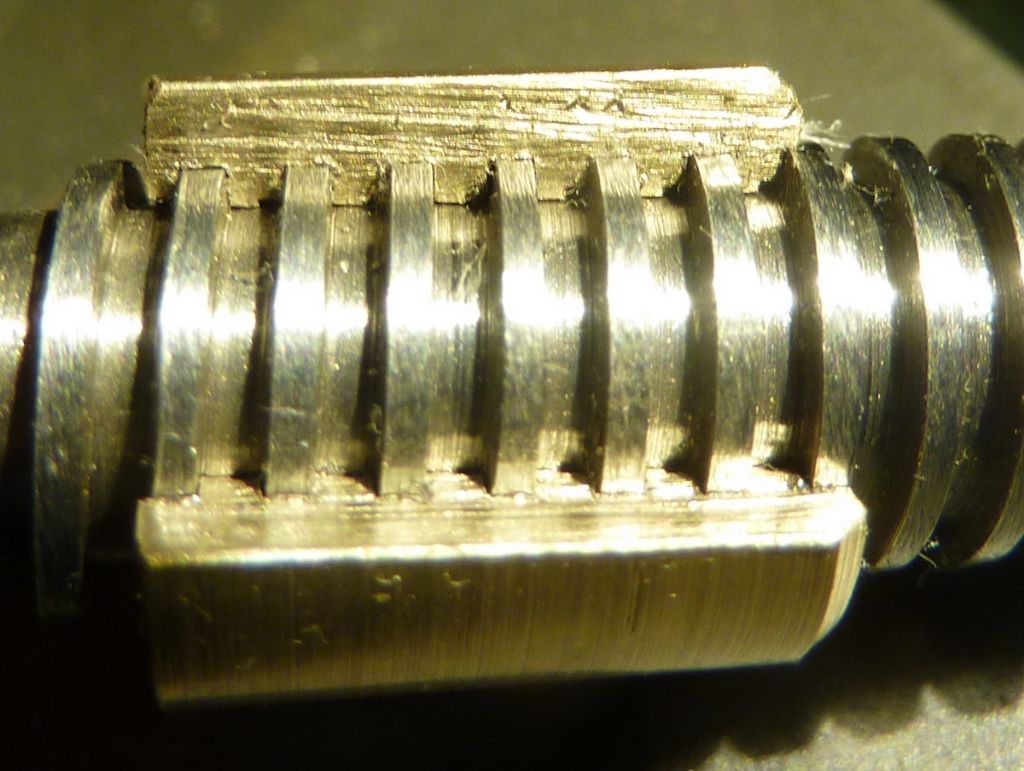
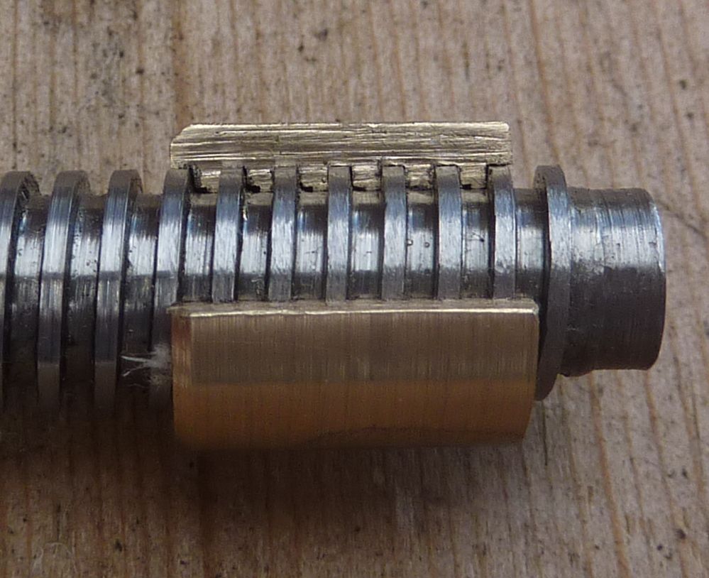
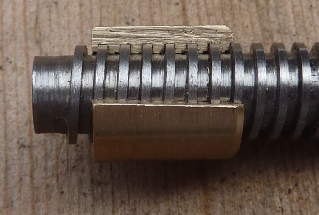
                                            I took Paul's advice and sectioned the left handed nut. I generally find that my compact camera is pretty good at really close up inspection so I took some photos in daylight and artificial light. None of the photos is perfect but I present the better ones here for your personal perusal.

                                            The nut (before sectioning) was very tight on the thread and I could only get it onto the thread by clamping it in the vice. It got stiffer the further I went and I never quite got it all the way through. I got the same result from either end. Had the cutting tool not come loose I was intending to take one more thou (radius) to deepen the thread.

                                            The threads on the tailstock screw measure with calipers at 0.85mm. I think there is wear but it is pretty even along the screw. For comparison the very end thread on the compound screw measures a full millimetre.

                                            The odd 'step' in the thread is because I was unable to correctly 'pick up' the thread for the second session so you have a partly cut thread overlapping the almost fully cut one.

                                            p1070513.jpg

                                            p1070512.jpgp1070510.jpg

                                            p1070507.jpg

                                            #486359
                                            Andy Carlson
                                            Participant
                                              @andycarlson18141

                                              A little update on the cross slide nuts…

                                              I've made a short section of male thread from some 3/8 steel bar so that I have an unworn example to test with. This did not turn out perfectly. Practice nut No 2 went most of the way on with a healthy degree of drag but is quite tight on the last half inch. As far as I can tell this is the result of pitch error. I noticed when tidying up the point where I stopped threading that the tool did not pick up the thread correctly at that end even though the screw cutting train had not been disengaged and the backlash was going the correct way. I can only conclude that the tool was pulling itself ahead of the leadscrew and into the backlash a little.

                                              For practice nut number 3 I made another threading tool from the 3mm HSS mills to 1 thou over the nominal groove width. I was expecting the usual struggle and fettling when I finished cutting but the test thread screwed in at the first attempt. I foolishly allowed myself to start thinking that I was getting the hang of it and moved on…

                                              Practice nut 3 has been cleaned up and pressed into recess in the spare saddle. That put an immediate stop to any impression of progress. Even the worn feed screw would not screw in without a major struggle. Clearly the nut had compressed significantly. My plug gauge would not go in. A quick touch with a tapered reamer allowed the plug gauge in and the worn screw went in after cleaning up a slight wear ridge that was making it oversize. This revealed that the screw was not quite parallel to the slides – an error of about 1mm in 90mm.

                                              I've concluded that trying to make a correct concentric nut, press fit it into the saddle and expect it to work is not going to fly. I've now started making a tap which hopefully will be able to finish cut the nut threads in situ and allow the correct alignment for the feed screw. The tap needs over-width threads and underwidth grooves… so another threading tool was made. Including the rejects I think I've made six so far. I'm glad I'm using 3mm HSS – it would take a lot longer to make six of them from 6mm HSS.

                                              #486374
                                              not done it yet
                                              Participant
                                                @notdoneityet

                                                … Clearly the nut had compressed significantly. My plug gauge would not go in. …

                                                That would indicate that your ‘press-fit’ was too tight? Less interference on the the outer diameter would be the better refinement. Even with a sliding fit, the nut could be secured with, say, a ‘bearing fit’ grade of loctite without any distortion to the threads, or fear of it turning in the housing.

                                                #486412
                                                Andy Carlson
                                                Participant
                                                  @andycarlson18141

                                                  The nut was based on measurements of the original one that came out. That was a bit uneven but has a taper from 511 thou at the fat end to 506 at the thin end. The lower measurements at the fat end are 509 thou so I was cautious and made the new nut to 509 thou tapering to 506.

                                                  To be honest though the clearance is not the big issue – that could be solved by changing the tolerances when I make the nut. The alignment issue is the big problem and I think that for this I need to do the finishing cuts on the nut thread in situ… which will hopefully also mean that I have control over the final major and minor diameter too.

                                                  Whether the alignment issue is coming from the pressing operation or the hole is not clear but I did press it out and back in again after turning through 180 degrees. That made it worse, but still to the same side… so I removed it again and put it back how it was originally. I think this makes it pretty certain that the error is not coming from the nut.

                                                  #486416
                                                  Hopper
                                                  Participant
                                                    @hopper

                                                    You need to measure the hole. It should be parallel. Then you turn the nut so it is half a thou bigger or so than the hole but parallel along its length. And as you say, turn the outside diameter in the same set up as you bore the hole and cut the thread so it is all concentric.

                                                    Trying to press in a nut with 5 thou taper is likely to go all over the place.

                                                    Edited By Hopper on 18/07/2020 11:30:14

                                                    #486420
                                                    Nigel McBurney 1
                                                    Participant
                                                      @nigelmcburney1

                                                      unlike v threads ,square threads have clearance on the o/dia when cutting a square thread during my apprenticeship I was told that these threads have 10 thou clearance on the odia,this applied to all such threads irrespective of diameter. I have made a number of square threads over the years from the brake screw on a 1 1/2 inch Allchin TE to some full size brake shafts on Avelings and Fowlers and a very long screw for a sluice gate,all these had a good clearance,Its the fit of the flank of the threads that matters,looking at the photos of the cut brass nut,top and bottom clearance looks minimal or nil. One of my next jobs is 4 square threads for the jacking screws of a 1920s showmans living van,bit difficult at 4 tpi, one unusual feature of the thread is that the depth of thread is half the normal depth.

                                                    Viewing 25 posts - 51 through 75 (of 79 total)
                                                    • Please log in to reply to this topic. Registering is free and easy using the links on the menu at the top of this page.

                                                    Advert

                                                    Latest Replies

                                                    Home Forums Manual machine tools Topics

                                                    Viewing 25 topics - 1 through 25 (of 25 total)
                                                    Viewing 25 topics - 1 through 25 (of 25 total)

                                                    View full reply list.

                                                    Advert

                                                    Newsletter Sign-up