Injection moulding and ISO tolerances

Advert

Injection moulding and ISO tolerances

Home Forums Beginners questions Injection moulding and ISO tolerances

Viewing 15 posts - 1 through 15 (of 15 total)
  • Author
    Posts
  • #236430
    John Munroe
    Participant
      @johnmunroe13164

      Hi

      Usually, do mould factories use ISO tolerance classes like fine, medium, coarse, etc.? Like those here.

      If I'm reading that correctly, with class "medium", a 1000mm long piece will only have max +/-0.8mm, which is 0.08%. Doesn't the resin alone shrink by 0.5%?

      Any thought appreciated.

      John

      Edited By John Munroe on 27/04/2016 11:19:47

      Advert
      #8113
      John Munroe
      Participant
        @johnmunroe13164
        #236433
        Clive Foster
        Participant
          @clivefoster55965

          I imagine that its like shrinkage allowance for castings. The makers know how much the material is supposed to shrink by and make allowance in the design then try to keep the component to componet variation within specified limits by careful process control.

          Clive.

          #236437
          Mark Barron
          Participant
            @markbarron78673

            For injection moulded plastics, you'll struggle to use the standard ISO tolerances. I'd suggest using DIN 16 901 tolerances as these take into account the mould tool construction and moulding material.

            Note that the the post-moulding shrinkage is covered in the tolerance.

            Mark.

            #236438
            Jeff Dayman
            Participant
              @jeffdayman43397

              Shrinkage and tolerance range vs part size varies with resin type. For a specific resin you could check a guide like SPI aq102 "guide to standards and practices for injection moulders" for tolerance ranges that can be held. Shrinkage rate data can be found either in matweb.com or from resin maker's datasheets for specific resins. Note that the aq102 guide is a secured PDF and is not a free document.

              Normally a part is designed and when sent to mould makers the size of the CAD model is enlarged by the shrink factor to make a CAD model for tool cutting. Shrink factors are usually listed as a range, ie 1.005 to 1.007 for a general purpose polycarbonate like Lexan 141 ™ . For normal commercial plastic parts the median of this range is chosen, ie 1.006 for general purpose polycarbonate like Lexan 141 ™ .Tool/mould is cut with this enlarged model, then first shots are moulded with the tool/mould. A detailed first article inspection (FAI) is made of all critical dimensions of the moulded part to make sure the mould is correct. If errors are found, mould is tuned/adjusted to bring the dims in spec.

              After mould is verified as correct or has been tuned / adjusted until it is, production starts. After the moulding process is stable, a statistical process study is done to ensure the critical part dimensions are process capable and fall within the SPI aq102 tolerance data for the resin and the size range of the part.

              Essentially the part tolerances that can be held for an individual resin is only directly dependent on the shrink factor within the range of that shrink factor. Other variations in resin within a batch and batch to batch, and process variations in the moulding press with melt heat, clamp pressure, cooling temps etc, do affect range of tolerances that may occur, and the aq102 guide's tolerance range data is based on a large study of these factors for each major resin type.

              Injection moulding of plastics for making high precision parts is not simple. Please PM me if you have specific questons. JD

              #236442
              John Munroe
              Participant
                @johnmunroe13164

                @Jeff But do mould makers typically use this ISO tolerance class system though? Don't they usually just specify the machining tolerances and the resin tolerances?

                #236445
                Muzzer
                Participant
                  @muzzer

                  Moulding isn't a science although there's a fair bit of science in it.

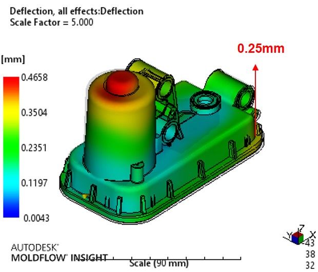
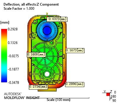
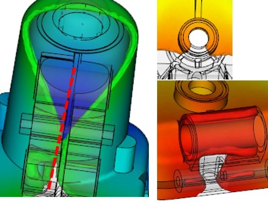
                  Usually, you take the 3D CAD model and do simulations on it to estimate the distortion that's likely to occur when it solidifies. The position of the gates, the moulding pressure, the moulding time etc all affect how the plastic flows into the cavity, the various fronts fuse together and then the whole solidifies. If the final result looks sensible, the tool is made and you try it for real. At that point you have another round of optimisation with real parameters (at the moulding machine itself) and hopefully end up with a solution that works for you. If required, the next stage is to modify (remake) the tool so that it sort of pre-compensates for the shrinkage you will see, so that after shrinkage and distortion, it's close to what you want. Nice if you can avoid that extra step.

                  Moldflow(c) from Autodesk is probably the industry standard software for this FEA analysis. Here are some pictures fro a recent analysis. The first parts came off about 2 weeks ago are are pretty close to what was predicted. That's down to having an experienced moulder and materials supplier as much as anything else.

                  Deflection

                  Flatness

                  Weld lines

                  To answer the question, the original part needs to be drawn and toleranced according to the application using std GD&T methods, using ISO or otherwise, with critical characteristics clearly defined. So if you need to weld it (laser, ultrasonic etc), there will be a flatness tolerance so that you don't have to overclamp (and hence prestress) the part, if you need to press a bearing or shaft into it, there will be tolerances for position, squareness, fit tolerance etc. Quite what the final dimensions of the mould tool are is more down to the moulding company.

                  Murray

                  #236450
                  John Munroe
                  Participant
                    @johnmunroe13164

                    @Murray Is it actually the responsibility of the part designer (customer) or the mould maker to ensure that the plastic flows right? Or should the mould maker study the flow of the given part prior to giving a quote (so that the flow analysis work will be accounted for)?

                    #236452
                    Muzzer
                    Participant
                      @muzzer

                      Ideally you will select a moulder who will collaborate with you in the early stages – and you will take account of the materials, processes and experience he has available during the design process. That's true of most components. The kind of design process where you design something and simply find someone to make it may work but is unlikely to be optimal either in design or cost.

                      Most suppliers will look at the drawings and specs and give feedback (DFM or APQP) about what they can and can't make. It works both ways because if they agree to make it, you are likely to inspect against the specs and drawings when you receive parts from them and reject any that don't comply. But as mentioned, you also miss the opportunity to get a better / cheaper product if you don't involve them until it's too late. So it may be perfectly possible to make but cost more or be less robust than it might be.

                      #236453
                      Muzzer
                      Participant
                        @muzzer

                        double post

                        Edited By Muzzer on 27/04/2016 14:32:59

                        #236478
                        Jeff Dayman
                        Participant
                          @jeffdayman43397
                          Posted by John Munroe on 27/04/2016 13:10:10:

                          @Jeff But do mould makers typically use this ISO tolerance class system though? Don't they usually just specify the machining tolerances and the resin tolerances?

                          In my experience over 32 years at work with North American, British, Portuguese, and far Eastern mouldmakers, no, they don't use your ISO system as presented. There is a HUGE variation from shop to shop and also depending on whether parts are for cars, medical machines, office machines, appliances, or consumer products. There may be mould shops in Europe or other countries that do use your system as presented, but I haven't worked with any.

                          Is your enquiry personal interest or for a commercial venture or to settle a dispute with a moulder at your work? This forum is for hobby and personal use only, not for commercial or work enquiries. JD

                          #236507
                          John Munroe
                          Participant
                            @johnmunroe13164

                            @Jeff It's just out of curiosity, because I always thought plastic parts use ISO tolerances but didn't know the actual values. Those values just seem a bit tight to me.

                            #236533
                            Mark Fry
                            Participant
                              @markfry71618

                              Murray,

                              If the moulder gives the part designer advices for changes back and forth, wouldn’t it be a rather arduous process? Part designers don’t know much about flow analysis, right?

                              Edited By Mark Fry on 28/04/2016 10:19:28

                              #236540
                              Mark Barron
                              Participant
                                @markbarron78673

                                Mark,

                                It's quite common to have at least 2 design iterations before the part design is approved for tool manufacture – common issues are injection gate location, parting line position(s) and under-cuts. With this in mind, mould flow software is now used by the part designer to try and reduce the iterations at the toolmaker.

                                John,

                                The standard ISO tolerances are not so good for moulded part design. I use the DIN 16901 tolerance system as it is specifically for moulded parts.

                                Mark.

                                #236552
                                Muzzer
                                Participant
                                  @muzzer

                                  Some parts designers are doubtless very knowledgeable and capable but they wouldn't normally be designing the mould tools as well. Similarly they wouldn't be expected to go into the factory and set up all the machines.

                                  Yes, it is rather arduous getting designs optimised like this and you try to get it as close as you can to begin with. But in a competitive market you can rarely afford to throw margin away with every part shipped. If you are some all seeing, all knowing, all around design genius in every field your products involve, then perhaps you will know better than all of your suppliers, no matter how experienced they are. There are people who believe themselves to be in that category but it tends to mean they simply stopped learning years ago and have an ego problem.

                                Viewing 15 posts - 1 through 15 (of 15 total)
                                • Please log in to reply to this topic. Registering is free and easy using the links on the menu at the top of this page.

                                Advert

                                Latest Replies

                                Home Forums Beginners questions Topics

                                Viewing 25 topics - 1 through 25 (of 25 total)
                                Viewing 25 topics - 1 through 25 (of 25 total)

                                View full reply list.

                                Advert

                                Newsletter Sign-up