Induction hob – any workshop uses?

Advert

Induction hob – any workshop uses?

Home Forums Electronics in the Workshop Induction hob – any workshop uses?

Viewing 19 posts - 1 through 19 (of 19 total)
  • Author
    Posts
  • #31774
    Robin Graham
    Participant
      @robingraham42208
      Advert
      #174699
      Robin Graham
      Participant
        @robingraham42208

        Hi. I have been offered a functional induction hob with a cracked top on freegle – seems no-one else wanted it, so (being of a scavenging disposition) I put in for it thinking that there must be some use (eg an annealing oven?) for some moderately chunky induction elements and control circuitry. Bound to come in handy one day isn't it…

        But is it? Anyone out there ever done anything useful with anything like this, or have any ideas?

        Regards, Robin

        #174703
        _Paul_
        Participant
          @_paul_

          I have heard of these things being used as bearing heaters for when you need to warm one up to aid fitting…

          Personally when changing spindle bearings I balance mine on a 60w bulb (elf & safety police do not respond)

          Paul

          #174705
          Ed Duffner
          Participant
            @edduffner79357

            I used my halogen hob to heat a bearing for about 30 seconds to fit onto a lathe shaft which was cooled in the freezer over night. I've sometimes wondered if a technique like this could be used to heat a solder bath to flow-solder a boiler together, one end at a time? Might only be good for low temp solder though.

            Ed.

            #174708
            martin perman 1
            Participant
              @martinperman1

              Robin,

              I the hob works the best thing will be it will only heat where the object contacts so no heating unnecessarily.

              Martin P

              #174716
              Les Jones 1
              Participant
                @lesjones1

                Hi Robin,
                At the moment on the Yahoo hobbycast forum there is discussion on using an modified induction hob for melting metal. You may have to join the forum to read the messages.

                Les.

                #174718
                Russell Eberhardt
                Participant
                  @russelleberhardt48058

                  Posted by martin perman on 04/01/2015 14:12:41:I t

                  the hob works the best thing will be it will only heat where the object contacts so no heating unnecessarily.

                  No. It works by induction not conduction. An alternating magnetic field induces a current in the base of the pan and that current causes the heating.

                  Russell.

                  #174732
                  Robin Graham
                  Participant
                    @robingraham42208

                    Thanks for your replies. Sounds like there may well be some mileage in this. Les, thanks for the link to the Yahoo forum. Interesting stuff. My interest is more in heat treating than melting, but the principle is the same obviously.

                    Rang the guy up to say I'd take it, and he mentioned he had another stashed away which I was welcome to, so eight drivers in all I guess!

                    Regards, Robin

                    #174753
                    Muzzer
                    Participant
                      @muzzer

                      Induction heating is often used to directly heat workpieces for brazing etc, in conjunction with an inert or reducing atmosphere. The main issue with a cooker hob may be that it's designed to heat a flat surface (pan face) adjacent to the surface of the hob. An industrial heater would often have a hole through the middle to allow more flexibility.

                      No idea what they look like inside in terms of the induction loop(?) but it may be more useful with the hob surface (glass?) removed, notwithstanding the need to maintain safety isolation between the mains circuits and the workpiece. There is some info on Wikipedia of course. Sounds as if they use an LC resonant circuit operating typically between 20-100kHz or higher. Naturally there are lots of aluminium foil hat wearers who believe them to be the work of the devil but we don't let their sort anywhere near the workshop.

                      I think I've seen single element induction heaters in places like Aldi. As you say, it would be interesting to hear if anyone has found them useful in the workshop given how cheaply they can be obtained.

                      Murray

                      #174754
                      Bazyle
                      Participant
                        @bazyle

                        Just to follow up on Ed's post: solder bath would coat everything in solder which would be rather expensive. However there is a standard industrial prociedure where the joints are coated with solder paint and the whole immersed in a 'salt bath' to melt the solder. The salt is not rust inducing Sodium Chloride but something inert that melts at the required temperature. I can't remember why this is preferable to plain heating but possibly to avoid oxidation and provide fluxing and cleaning properties.

                        #174768
                        Robin Graham
                        Participant
                          @robingraham42208

                          Murray, I too wondered if the fact that hobs are designed to heat a flat surface might be a problem, but then thought that as the 'driver' can only 'see' a (complex) reactance it might be possible to wind a coil of similar inductance in whatever geometry one wished. It seems that the guy on Yahoo Les linked to has done just that, and wound what is essentially a soleniodal coil around a steel crucible with good results for melting aluminium (or aluminum in his case). It seems from what he says that the circuitry in the oscillator can detect the presence of a resistive load and regulates the power ouput accordingly, which might (or might not) be useful.

                          It'll be fun to play about and see what can be done though.

                          Regards, Robin

                          #174771
                          Jon
                          Participant
                            @jon

                            I have a DeDietrich induction hob outside I put my knee through on Christmas Eve, good timing. Just for cooking it draws more than 32A to give you an idea.

                            Below lifted from wiki, 25mm steel round using 15KW! That's ike running a 20HP motor.File:Induction heating of bar.jpg

                            #174797
                            David Jupp
                            Participant
                              @davidjupp51506

                              It might be possible to rig up something similar to **LINK**

                              Having spoken to the manufacturer, these devices are somewhat self limiting when working with steel – once above curie temperature, one of the major heating mechanisms (magnetic hysteresis) lost.

                              #174849
                              frank brown
                              Participant
                                @frankbrown22225

                                I read Bazyle's post and I could not make sense of it as I was involved with a very different sort of solder bath many years ago. I then consulted Wiki to see what they had to say about "solder bath"s. They refer to it as "dip soldering", assemblies are prefluxed and dipped into a static bath of solder.

                                What we called the solder bath, is actually a wave soldering bath. A long bath of molten solder has rollers mounted across it, just under the solder level, when they are rotated, you get a little static wave of solder appear across it. So printed circuit boards were put on a track and slowly run down the length of the bath and the wave of solder just wiped the underneath of the board, soldering the leads to the tracks by means of surface tension,

                                In those days the leads were cropped in a special machine to keep the leads that poked through the board to a constant length. The big problem was that the ends of the leads were formed into a T shape. You could turn an assembled board upside down and the components would not fall out, very good!, but it was extremely difficult to remove a faulty component once soldered.

                                I think that induction hob has an interesting future in the workshop, The biggest problem I can see is that the power supply would not be transformer isolated so using solenoid type coils for heating steel rods to harden them, would need some form of high temperature tube to insulate the coil. Perhaps a tube of Pyrex glass?

                                Frank

                                #174868
                                Mark C
                                Participant
                                  @markc

                                  Frank, you can buy ceramic beads for insulating all over the Internet (and eBay) which would probably work nicely as they are short and will follow a bend?

                                  Mark

                                  #174869
                                  Muzzer
                                  Participant
                                    @muzzer

                                    Most through hole component leads are left straight nowadays. When manually fitted, they are usually preformed to the correct length before insertion. Large components are held in place with sprung carriers to keep them against the top face of the board before soldering. The wave soldering machines pump molten solder over a raised dam to make it wet the underside of the board. Specially machined shields are used to protect delicate components against the effects of the solder by keeping them out of the solder wave.

                                    Before "the widespread availability of cheap labour", a steel plate with corresponding holes would be fitted below the PCB and a blade run across the bottom of it after the through hole compts had been inserted, often automatically. The plate would be dropped away and the board soldered. When I first started working in electronics product design and manufacture, we were required to have bent leads (before soldering) to provide additional resistance to pull-out. It doesn't seem to have been necessary with hindsight, although it certainly cost many hours of extra effort during desoldering and repair.

                                    As the salt bath Bayzle mentioned uses molten salt, not an aqueous solution, the question of rusting wouldn't apply as there is no water present, even if using sodium chloride. No experience of it myself but I Googled "salt bath brazing" and got some relevant-looking results.

                                    Murray

                                    #174888
                                    Mark C
                                    Participant
                                      @markc

                                      Murray,

                                      There definitely is water even in a hot (300+ degrees) salt bath but I don't know what chemistry is involved. The reason I know is from involvement in salt bath heat treatments and the water level is monitored as it affects the heat transfer properties of the salt (we are talking nitrate salts by the way – I wonder if that is what Bazyle saw?).

                                      Mark

                                      #174898
                                      Roger Hart
                                      Participant
                                        @rogerhart88496

                                        With around 1.5Kwatt power you 'might' be able to melt non-ferrous in a well insulated crucible. But to do this you will probably need to re-shape and rewind the main inductor. This implies measuring its inductance 'as is' and trying to get close-ish with the new one. Not one for the faint hearted…..

                                        #175766
                                        Robin Graham
                                        Participant
                                          @robingraham42208

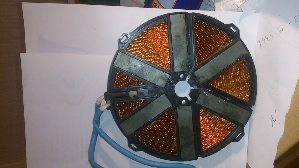
                                          Well, after delay due to 'flu, finally got round to picking up the hobs. For anyone else who hasn't seen how the elements are constructed but might be interested:

                                          dsc_0769.jpg

                                          I'd naively assumed that the element would be a simple 'pancake' coil, when I would have been able to calculate the inductance at least roughly, but the six ferrites(?) scupper that, so further progress will have to await the emergence of function generator/scope from packing cases .

                                          Robin.

                                        Viewing 19 posts - 1 through 19 (of 19 total)
                                        • Please log in to reply to this topic. Registering is free and easy using the links on the menu at the top of this page.

                                        Advert

                                        Latest Replies

                                        Viewing 25 topics - 1 through 25 (of 25 total)
                                        Viewing 25 topics - 1 through 25 (of 25 total)

                                        View full reply list.

                                        Advert

                                        Newsletter Sign-up