Indexing arms on dividing head are spinning freely

Advert

Indexing arms on dividing head are spinning freely

Home Forums General Questions Indexing arms on dividing head are spinning freely

Viewing 13 posts - 1 through 13 (of 13 total)
  • Author
    Posts
  • #653972
    Jim Gardner
    Participant
      @jimgardner97734

      Hello, I am new to the group today so will be heading to the "introduce yourself" page shortly. I find myself here because I am about to use an old dividing head for the first time but immediately ran into a problem.

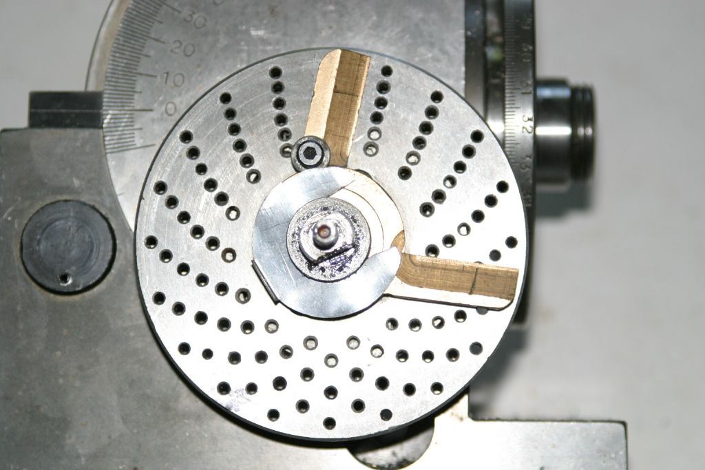
      The brass indexing arms fit over the centre shaft but there is nothing to provide any tension/friction to keep them in place. The shaft has what could be a circlip grove in it approximately 1mm out from touching the arms, so I am assuming there is a brass? washer type piece that presses against the arms to stop them spinning freely.

      Could someone tell me what pieces are missing please. I.E brass shim or spring or something I haven't thought of?

      Many thanks,

      Jim.

      Advert
      #29309
      Jim Gardner
      Participant
        @jimgardner97734
        #653991
        Baz
        Participant
          @baz89810

          There should be something to provide some friction so perhaps a wave washer and circlip are missing.

          #653995
          Fulmen
          Participant
            @fulmen
            #653996
            Howard Lewis
            Participant
              @howardlewis46836

              Firstly, Welcome.

              How old, and how big is the Dividing head?

              It sounds as if you have the Dividing Plates and Handle that go with the Dividing Head.

              What make?

              Pictures always help.

              Spares might be available.

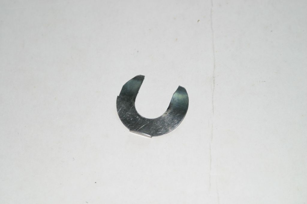
              There should be a thin, spring steel "washer" (For want of a better word ) that fits into the groove and presses onto the two arms, to provide eniugh grip to stop them moving by accident.

              Do you have the chart giving the turns and holes needed for each of the plates to give a required number of divisions? If you have; check it; errors have been known! I was caught by incorrect info on the set up for 13 divisions; and then found other errors.

              The chart will be specigfic to your particular DH. Depending on the make, the ratio of the worm and wheel could be almost anything. (36; 40 or 90:1 seem to be popular ratios. ).

              On a Vertex HV6 Rotary Table, you would be looking for part No. 52 which would be described as a "Sector Spring"

              Howard

              #654004
              John Purdy
              Participant
                @johnpurdy78347

                Jim

                I suspect you are missing the part shown in the photos below. It is a dished half washer and fits in the groove you mention to apply some tension on the arms to keep them from moving but still able to rotate to position them. Should be easy enough to make something suitable.

                John

                img_7002.jpg

                img_7005.jpg

                #654011
                Jim Gardner
                Participant
                  @jimgardner97734

                  Many thanks for all replies so far.

                  Unfortunately there is no makers name I can see but I assume reasonably old. As for how big, what is used as a reference for DH size?

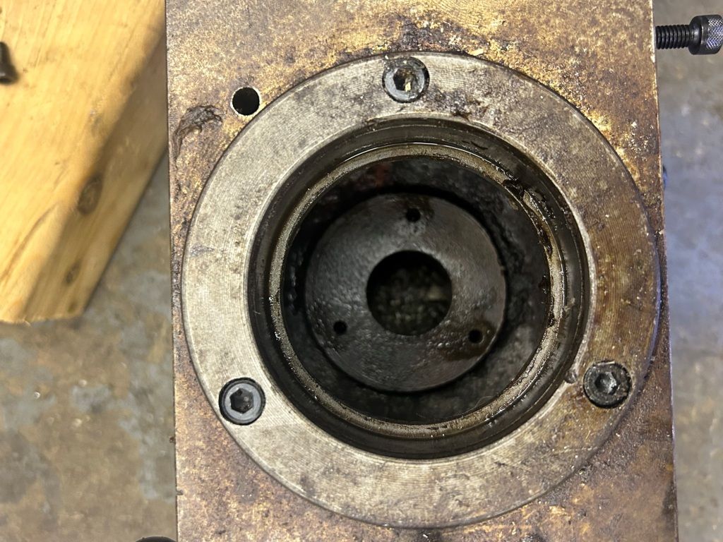
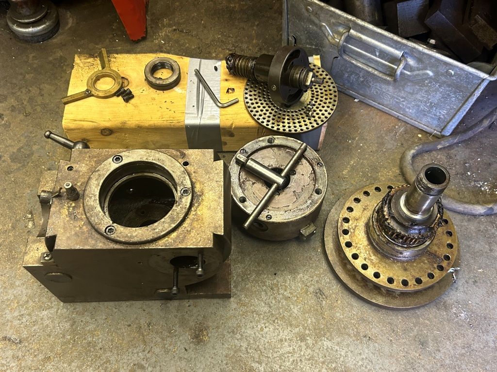
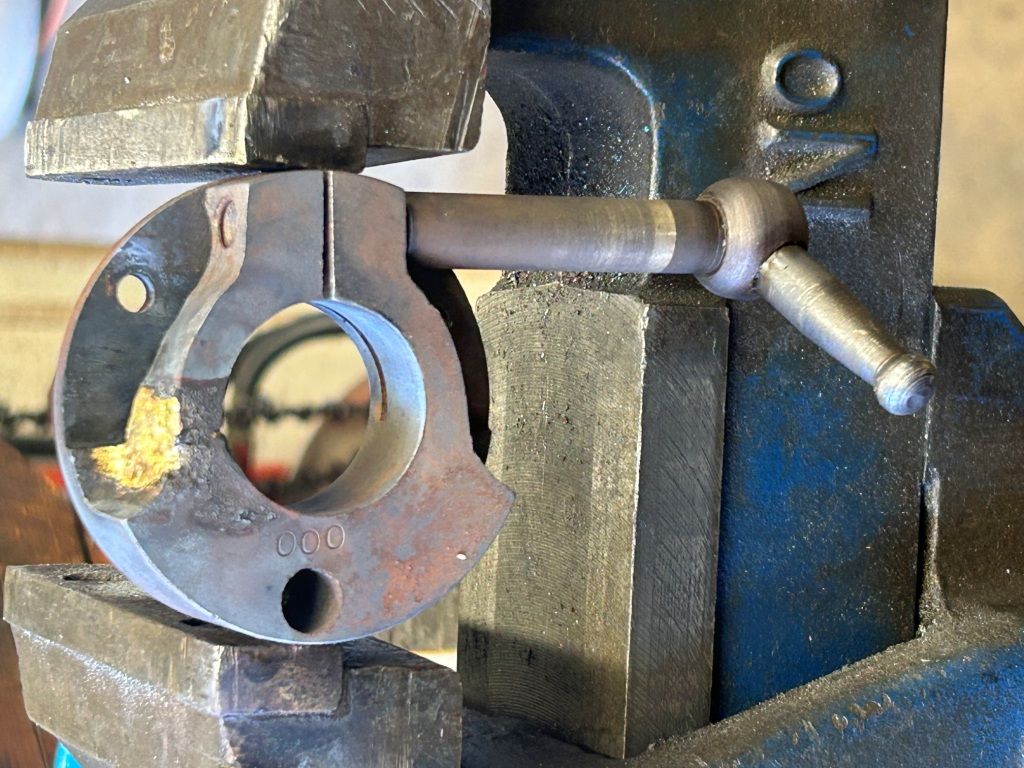
                  Due to its age and not having been used for at least 25 years, and to clean it all up so I can use it, I decided to strip it. Unfortunately I found the "brake" is broken. Without a makers name, how would I go about getting spares?

                  I have brazed it just now but not sure how strong it will be. Sorry for the almost certain incorrect terminology.

                  Re the indexing/selector arms, I will try and find a wavy washer first but make a brass one if not.

                  Yes I do have the handle/pin and 3 plates.

                  I have photos I would like to post but can't find how to do that despite trying hard.

                  Thanks again.

                  Jim.

                  #654021
                  Frances IoM
                  Participant
                    @francesiom58905
                    #654029
                    Ady1
                    Participant
                      @ady1

                      Welcome to the nuthouse

                      Some places want you to drink a yard of ale in one go to become a member

                      In here the right-of-passage challenge is to figure out how our pictures system works thumbs upcocktail

                      #654032
                      Fulmen
                      Participant
                        @fulmen

                        I made my replacement from a spare brake hose clip I found in a drawer:

                        #654033
                        Jim Gardner
                        Participant
                          @jimgardner97734

                          img-9301.jpgimg-9300.jpgLets see if the advice Frances gave works for me.img-9299.jpg

                          #654137
                          Jim Gardner
                          Participant
                            @jimgardner97734

                            I have just noticed some replies to this post show on my phone, but not on my laptop.

                            #654144
                            Howard Lewis
                            Participant
                              @howardlewis46836

                              being pessimistic, have doubts about bthe stregth of the repair.

                              BUT, if you use your lathe to make a new one, the brazed D H lock might last long enough for you to complete the machining, and so be able to fit a replacement locking device.

                              It might even be worth extending the machining on both sides a little further towards the holes.

                              FWIW, I would suggest making the bore as close a fit on the mating part as possible, to minimise the bending of the arms. It might be worth extending the depth of the slot until it intersects the solid part of the clamp, to make the arms more flexible and to move the point of bending.

                              The worm is likely to be single start, so if you count the teeth on the wormwheel, that should tell you the ratio, which will be a start.

                              Somewhere on here, there was a spreadsheet showing the calculations for a Rotary Table with a 90:1 ratio.

                              Serach for HV6, spreadsheet. That should allow you to find and copy the spreadsheet, so that ikt can be edited to suit your purposes.

                              If you copy it and amend the formulae from 90:1 to the ratio of your DH,you should be able to construct, and print a chart showing the divisions available from your DH and the division plates that you have.

                              Good Luck!

                              Howard

                            Viewing 13 posts - 1 through 13 (of 13 total)
                            • Please log in to reply to this topic. Registering is free and easy using the links on the menu at the top of this page.

                            Advert

                            Latest Replies

                            Home Forums General Questions Topics

                            Viewing 25 topics - 1 through 25 (of 25 total)
                            Viewing 25 topics - 1 through 25 (of 25 total)

                            View full reply list.

                            Advert

                            Newsletter Sign-up