Increasing Print Area

Advert

Increasing Print Area

Home Forums 3D Printers and 3D Printing Increasing Print Area

Viewing 18 posts - 26 through 43 (of 43 total)
  • Author
    Posts
  • #468454
    Joseph Noci 1
    Participant
      @josephnoci1

      Mmm, not sure what happened to my post – Added it, but the post did not appear in the latest post list???

      Only appears in 'more latest posts' …??

      EDIT – and NOW it appears after I added this post//


      Edited By Joseph Noci 1 on 01/05/2020 21:23:11

      Advert
      #468562
      Mark Simpson 1
      Participant
        @marksimpson1

        Neil

        PETG is challenging, but yes I can print it.

        It's not a flexible filament though, that's TPU. With thin non bowden printer all it needs is a guide between the feed wheels and the heat brake. Having this little guide also makes changing filament of any kind easy.

        I have the same Factory 3D printer as you, easy to make up a guide from another bit of M6 Ptfe lined tube; thanks I will do that.

        Do you have some starting point Cura settings for PETG? I am getting nowhere.

        Thanks Mark

        #468626
        Neil Wyatt
        Moderator
          @neilwyatt
          Posted by Joseph Noci 1 on 01/05/2020 21:10:53:

          Thanks Neil.

          What sensor do you use for the auto-level process? And how does that process work on your printer? How many points ( a grid?) does the system check for height variation across the print platten?

          Hi Joe, I thought I was clear – I level manually!

          I use four points.

          With this machine, I use practical results to check and judge on results. I don't see FFD printing as a micron-accuracy exercise, but as you are aware you can build in adjustment.

          I'm just completing the largely 3D printed Newtonian telescope, simple 3-screw adjustments for each mirror. (three allows up down adjustment as well as tilt).

          I have only just come in from testing it, I left the tube over length and if focused on clouds at almost completely wound in, which was ideal with the eyepiece I was using. I now know exactly how much to shorten the tube.

          First impression is that the mirror appears excellent, looking at leaves on top of a tall poplar at about 36x I could see minute insects flying around and the detail was as if I had the leaves in my hand. The real test will be on stars, of course. Rough collimation was easy, the final job must wait for some better fitting screws (on order), those I have ran out of adjustment.

          This is just a 6" mirror, a friend is making an optical tube assembly for a very, very good 18" mirror that has been in several telescopes before, including Hawker Siddley Astro Society's scope. Donated to our club, it has a focal length of about nine feet so it will be a real 'planet killer'. He's made a nine-point support for the mirror (uses the same principle as equalised railway brakes) and the tube will a reconfigurable one made of Pearl 22" bass drum shells!

          Neil

          #468627
          Neil Wyatt
          Moderator
            @neilwyatt
            Posted by Joseph Noci 1 on 01/05/2020 21:10:53:

            Probably going the be the most complicated 3D printer around, IF it actually gets to print anything!

            It does seem to be an exercise in ingenuity, but sometimes that's the best reason for doing things

            Neil

            #468709
            Joseph Noci 1
            Participant
              @josephnoci1

              Thanks Neil –

              Yes, I did read that you did manual leveling, but I assumed that was to get the table leveled to within 'nominal', and that the printers firmware did autoleveling by default. Most of what I find on internet seems to imply autoleveling is built in to almost all printer firmware these days.

              Its interesting that you do not do this – implies that either your manual leveling is very good, or its not that critical?

              I wonder what sort of error is acceptable without autoleveling.

              Nice on the telescope. Dug around on Utube looking at how the chaps grind the glass for those mirrors – quite amazing stuff. Not something I could ever consider here – No glass, no silvering cabability, etc..

              An 18inch mirror must weigh quite a bit! Clever use of the drum shells! I like that..

              Joe

              #468723
              Roger Whiteley
              Participant
                @rogerwhiteley62172

                Autolevelling using a sensor is normally configured into the firmware you program into the printer controller, if its not enabled in the firmware – I'm using Marlin 2.0.3; 2.0.5 and 2.0.5.3 on different printers that are all physically identical. I don't have any with bed levelling sensors – to bed level with a sensor the mainboard also needs to have the correct connectors for the sensor you are using – there are two main types, proximity, which uses a magnetic field, and a servo actuated touch sensor – the proximity versions are typically the ones used in industrial automation solutions – and since most 3D printer beds are not steel the magnetic response is a bit hit and miss.

                I have several Creality Ender-3's, most using the standard mainboard, only one, which is an Ender Pro, has a none standard board – that has a BigTreeTech SKR miniE3 – that board has direct sockets to use a BL-Touch servo actuated touch sensor – I have the brackets and cables, what I didn't realise when I ordered the kit from Aliexpress was that it didn't have the sensor, so that is now on its way somewhere…

                I bed level with a sheet of 60g/sqm thin laser printer paper, that's a good guide / starting point, but the Ender Pro wants at least 3/14's of a turn on each adjusting knob to put the bed closer to the nozzle – why 3/14's? well the 4mm threaded screw is of course 0.7mm, so dividing the circumference of the knob into 14's makes sense.. I paint alternate bumps with Tipp-Ex so they are easier to see.

                Getting the firmware onto the mainboard is a whole new learning experience, mostly not fun. On a couple of occasions I've spent days trying to figure out why it wouldn't compile and upload.

                #469066
                Neil Wyatt
                Moderator
                  @neilwyatt
                  Posted by Joseph Noci 1 on 02/05/2020 20:28:53:

                  Thanks Neil –

                  Yes, I did read that you did manual leveling, but I assumed that was to get the table leveled to within 'nominal', and that the printers firmware did autoleveling by default. Most of what I find on internet seems to imply autoleveling is built in to almost all printer firmware these days.

                  Its interesting that you do not do this – implies that either your manual leveling is very good, or its not that critical?

                  I wonder what sort of error is acceptable without autoleveling.

                  To get decent results I'd estimate you need to be within about 0.15mm, or half the nominal thickness of a typical first layer. Too close and the bead is spread very broadly and has 'blobby edges' , closer still and filament feed stalls or worse the tip is damaged. Too far and the initial beads don't join into a smooth surface or worse they just sit on the bed without adhering.

                  By checking the appearance of th4 bead I think +/- 0.05mm is achievable. The real limit is the flatness of the bed and sheet borosilicate glass is not ideal in this respect – mine has a slightly low corner.

                  Neil

                  #469146
                  Joseph Noci 1
                  Participant
                    @josephnoci1

                    Thanks for the info Neil.

                    Most of my mechanics are largely done, so now Its the electrical box – power supply and electronics, etc.

                    And then the extruder/hot end

                    The power supply seems not so simple!

                    The heated bed wattage appears to be quite a high requirement. I see specs anywhere from 0.4 watts per square cm, up to 1 watt. My bed primary area is 40cmx40cm – that means a heater from around 640 watts all the way up to 1.5KW . Most of the PCB style heaters seem to be 12v/24v . 1.5KW @ 24v is a little silly! It seems ABS is the one material needing high bed temps, above 100degC, while most others run between 50 and 70degC ?

                    Looks like I would have to use a mains type silicon rubber heater to be practical.

                    I see you use borosilicate glass – is that required? Many folk seem to use plain 4 or 5mm glass window glass, and even 5mm mirrored glass.

                    Seems we may only be able to bring in goodies via air freight from end June, maybe…so heaters and all must wait.

                    Joe

                    #469306
                    Roger Whiteley
                    Participant
                      @rogerwhiteley62172

                      I have a 12V mainboard system an Anet A8, and Ender-3's, which all use 24V – the biggest benefit is reducing the current through the flexible cabling and thereby reducing the chances of fire!. If you have a 40×40 print area – then this is smaller than a Creality CR10-Max – might be worth having a look at their website, CR10 Max.

                      That has two PSU's, one specifically for the bed. My latest Ender3 came with a Creality glass bed, as well as a magnetic PEI sheet, covered in little round dots. Nothing needs to be applied to print to the surface. I've you've not found it before, have a look at OpenBuild Community Forum – you might find something interesting there. I've been getting shipments from China and sending parcels out to the USA / Canada and Japan, there was a hiccup in the delivery chain, but its now working as normal – one parcel left here, in the Far North on a Friday morning and was in Chicago by Saturday.

                      #469346
                      Neil Wyatt
                      Moderator
                        @neilwyatt
                        Posted by Joseph Noci 1 on 02/05/2020 20:28:53:

                        Thanks Neil –

                        Yes, I did read that you did manual leveling, but I assumed that was to get the table leveled to within 'nominal', and that the printers firmware did autoleveling by default. Most of what I find on internet seems to imply autoleveling is built in to almost all printer firmware these days.

                        Its interesting that you do not do this – implies that either your manual leveling is very good, or its not that critical?

                        I wonder what sort of error is acceptable without autoleveling.

                        Nice on the telescope. Dug around on Utube looking at how the chaps grind the glass for those mirrors – quite amazing stuff. Not something I could ever consider here – No glass, no silvering cabability, etc..

                        An 18inch mirror must weigh quite a bit! Clever use of the drum shells! I like that..

                        Joe

                        Joe,

                        I can never forgive you! You've made me paranoid about my levelling!

                        That I said the limit on levelling is the flatness of my sheet of borosilicate glass which has a turned-up corner.

                        This is compounded by flexibility in the heater PCB and even in the aluminium carriage underneath.

                        After spending a couple of hours fiddling I've ended up putting the build plate through the dishwasher (too lazy to scrub the old PVA off by hand). Checked everything with a straight edge (a rather depressing experience).

                        I've put it convex side down with the best corner at 'home', also turned 90 degrees (it's 200 x215mm to fit between the levelling screws on Y rather than X axis) so now it homes over the glass.

                        Spent ages working from back left (fixed position) then back right (adjust x-carriage symmetry).

                        Then front right (adjustable) and finally front left (home position, adjustable).

                        The problem is that as you measure some way in from each point and you also need to refine the Z-position it's recursive process, but using a clean build plate makes this a little easier.

                        Finally, I've recoated with PVA and will print some large circles to check the levelling.

                        Of course, once it all warms up the levelling will go out a bit and I'll have to start again, but I'll use the quality around the ring's skirt as the test.

                        I've also been googling borosilicate build plates. They all claim to be 'perfectly flat' but I'm pretty sure the one I have now did as well…

                        #469354
                        Michael Gilligan
                        Participant
                          @michaelgilligan61133
                          Posted by Neil Wyatt on 05/05/2020 12:55:15:

                          I've also been googling borosilicate build plates. They all claim to be 'perfectly flat' but I'm pretty sure the one I have now did as well…

                          .

                          Never, ever, believe someone who claims a thing is ‘perfectly flat’

                          MichaelG.

                          #469355
                          Andrew Entwistle
                          Participant
                            @andrewentwistle

                            Hi Joe,

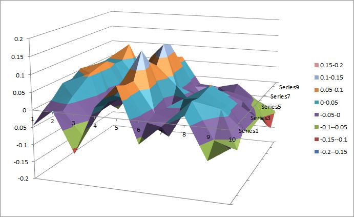
                            Here is a typical result on my machine from mesh bed levelling (10×10 matrix over about 200mm x 220mm) using a touch probe.

                            The probe itself is repeatable to better than 10um depending on speed. My machine has a single z-axis leadscrew on one side, driving a carriage based on delrin v profile wheels running in extrusions, so the limit on flatness is a combination of the aluminium bed flatness, perpendicularity of the z axis carriage and the y-axis which runs on a single linear bearing rail.typical bed topography.jpg

                            Edited By Andrew Entwistle on 05/05/2020 13:35:38

                            #469367
                            Roger Whiteley
                            Participant
                              @rogerwhiteley62172

                              Someone is a master of Excel smiley – I've never bothered trying to measure the flatness of any of my print surfaces – whilst I'm sure having a map in the mainboard and slicer might help, there are generally other more important things to worry about, like getting prints to stick. Which brings me onto…

                              I've been suffering occasionally but quite badly from print warping and/or refusing to stick to a PEI print surface.

                              The problem was in specific locations on the print bed, so I tried moving a big print off the cold corner of the bed seemed to help – back right. Then the opposite corner of the same model started doing the same thing… one successful print was followed by a not-quite-so-successful print. This model is printed diagonally as its 240 mm wide and just fits on an Ender-3 bed printed in that orientation. Although Octoprint whinges that it doesn't fit, it does, just.

                              Back to print warping… I have a pair of Ender-3's on a bench, eventually I realised it was the cold blast of air from the left hand printer's PSU that was prematurely cooling the print on the bed of the right hand printer. Strategically placing a box folder between the two as a temporary barrier has made the problem go away.

                              First world problems. So I can well believe printing ABS is a problem when you need a 100deg C bed temperature and absolutely no draughts, except beer, and that's off limits these days.

                              #469371
                              Andrew Entwistle
                              Participant
                                @andrewentwistle

                                Hi Roger,

                                The map is just because I can, the bed is levelled manually well enough. The value of the touch probe is that I can swap between bed surfaces without having to change the z-offset value. Even with >100C bed temperature and having an enclosure I have never been able to print anything larger than about 10cm in ABS without the edges lifting, despite coating the surface with ABS dissolved in acetone first.

                                Andrew.

                                #469374
                                Roger Whiteley
                                Participant
                                  @rogerwhiteley62172

                                  It looks great BTW, I've just not had a touch probe – all the braketry and an SKR miniE3 are set up and waiting for a parcel via Aliexpress which contains a BL-touch. It will be interesting to see what this Creality glass panel that arrived as an option with one of my printers measures up to flatness wise. All the flatness depends upon everything else being in perfect alignment, especially the X axis being as close to horizontal as possible. I spent a week in a Metrology lab, pity it was 40 odd years ago.

                                  #469412
                                  Joseph Noci 1
                                  Participant
                                    @josephnoci1

                                    That was not the intention Neil! If it worked as well as you wished for, why worry any further!

                                    I guess I am just going through the issues one by one, as I build this thing, to try and not build in problems – not sure that's possible, does require some experience and a good dose of hindsight..

                                    How does the heater PCB flex affect the glass bed? Is it somehow glued to the glass? I suppose if it is itself backed by the aluminium base ( with some insulator between?) then if the periphery or middle bowed it would press up against the glass. I have a 220v 750watt silicon heater pad – it is 300x300mm so a bit small for my table, but I will try it to start. It has a peel-off pad, which leaves a very sticky surface which will then adhere to the print plate. If one uses a heater in that way, then I guess the only distortion would be the print plate itself – be it aluminium or glass.

                                    Somehow though it seems problematic to adhere the pad to the print plate – makes it difficult to remove the print plate to clean etc? I suppose suitable connectors will help. A bit of experimenting with the stickiness of that heater 'glue' would indicate that it is a stick once and never remove – at least not without destroying the heater pad.

                                    Anyway, here I go again, turning someone elses thread into my build thread..Sorry Neil – When I have progressed a little further I will post a new thread..

                                    Joe

                                    #469418
                                    jason udall
                                    Participant
                                      @jasonudall57142

                                      Gentle readers…remember the longest axis for your part can be the diagonal of the built SPACE not just the platform.

                                      Also having layers non parallel with the face of the part can optimise your build strength.

                                      Though if you are building in a heated build cab say 70degrees your interlayer bonding improves s lot

                                      #469441
                                      Neil Wyatt
                                      Moderator
                                        @neilwyatt
                                        Posted by Joseph Noci 1 on 05/05/2020 17:59:34:

                                        That was not the intention Neil! If it worked as well as you wished for, why worry any further!

                                        I guess I am just going through the issues one by one, as I build this thing, to try and not build in problems – not sure that's possible, does require some experience and a good dose of hindsight..

                                        How does the heater PCB flex affect the glass bed? Is it somehow glued to the glass? I suppose if it is itself backed by the aluminium base ( with some insulator between?) then if the periphery or middle bowed it would press up against the glass. I have a 220v 750watt silicon heater pad – it is 300x300mm so a bit small for my table, but I will try it to start. It has a peel-off pad, which leaves a very sticky surface which will then adhere to the print plate. If one uses a heater in that way, then I guess the only distortion would be the print plate itself – be it aluminium or glass.

                                        Somehow though it seems problematic to adhere the pad to the print plate – makes it difficult to remove the print plate to clean etc? I suppose suitable connectors will help. A bit of experimenting with the stickiness of that heater 'glue' would indicate that it is a stick once and never remove – at least not without destroying the heater pad.

                                        Anyway, here I go again, turning someone elses thread into my build thread..Sorry Neil – When I have progressed a little further I will post a new thread..

                                        Joe

                                        No worries, the little bulldog clips being everything ogether but all three parts flex and the final position is a compromise between their stiffnesses… agricultural engineering at its best.

                                        Noting the above comment I've printed several parts diagonally before now – the tube rings with four protuberances (for clamp, mounting bars etc.) were rotated 45 degrees to get one protuberance in each corner, so it virtually filled the bed. Doing these was 'marginal' with the initial layer clearly better in some parts than others (a central portion at the front was high but an adjacent corner was a touch low). It would be nice to get it better, it's pretty good now.

                                        Neil

                                      Viewing 18 posts - 26 through 43 (of 43 total)
                                      • Please log in to reply to this topic. Registering is free and easy using the links on the menu at the top of this page.

                                      Advert

                                      Latest Replies

                                      Viewing 25 topics - 1 through 25 (of 25 total)
                                      Viewing 25 topics - 1 through 25 (of 25 total)

                                      View full reply list.

                                      Advert

                                      Newsletter Sign-up