Increasing Print Area

Advert

Increasing Print Area

Home Forums 3D Printers and 3D Printing Increasing Print Area

Viewing 25 posts - 1 through 25 (of 43 total)
  • Author
    Posts
  • #467647
    Neil Wyatt
    Moderator
      @neilwyatt

      My Factory3D clone of a Prusa i3 has one irritating feature… the x-travel is insuffcient to cover the whole buildplate in the Y-direction, even with careful setting up.

      Some 'crude engineering' today – basically cutting lengths of ground stainless rod and allthread to length and then replacing the Y-travel parts on the printer (like heavy duty Meccano).

      My setup now actually places the home position just off the buildplate, a minor inconvenience when checking the z-height but a bonus as nozzle purges don't make a lump on the buildplate.

      I do have to remember this when placing prints, but this is trivial as large prints have to be placed to avoid the bed clips (or the clips have to be moved to suit the print.) Anything small isn't affected.

      Advert
      #31633
      Neil Wyatt
      Moderator
        @neilwyatt
        #467655
        ega
        Participant
          @ega

          Neil:

          May I ask where you get your ground stainless rod, please?

          #467656
          I.M. OUTAHERE
          Participant
            @i-m-outahere

            I know what you mean ! I have the same printer !
            Have you run a test at or near full capacity ? IIRC there are some X,Y,Z axis travel settings in the firmware (possibly to act as soft limits on the opposite end of each axis To where their respective limit switches are ?) Can’t 100% certain as it is a while back that i had to re load Marlin on my board . I know there are these settings in the slicer i use -Cura to stop one from trying to print something bigger than the build plate .

            #467672
            not done it yet
            Participant
              @notdoneityet

              In Cura, I think you insert the maximum bed size and then it limits you, should you try to exceed those limits. I expect Neil will have simply inserted values for his table (if he uses Cura).

              #467690
              Iain Downs
              Participant
                @iaindowns78295

                As a matter of interest, Neil, are you still using the version of Cura which came with the machine?

                I have 14.12.1 and I seem to recall it was better than 'later versions'. However there seem to a number of major releases since then and, whilst the software seems to do everything I need, one feels left behind!

                Iain

                #467796
                Ronald Morrison
                Participant
                  @ronaldmorrison29248

                  In the newest version of Cura you would choose the printer you have in the setup section and it will set the build table size automatically. With a little digging you will be able to find this setting and make changes to the build table size. Do so with care, prints will not come out like you intended if the print head or table hit the end of their movement as the stepper motors will chatter a bit and then assume they are at the right location while they are not.

                  #467905
                  Neil Wyatt
                  Moderator
                    @neilwyatt
                    Posted by ega on 28/04/2020 16:38:45:

                    Neil:

                    May I ask where you get your ground stainless rod, please?

                    Just searched for 8mm stainless ground rod online, seems to be a speciality of 3D printer cnc specialists. Our usual suppliers only seem to do drawn rod.

                    Neil

                    #467916
                    Neil Wyatt
                    Moderator
                      @neilwyatt

                      I'm on a much, much more recent version of Cura 4.6, the latest issue.

                      Before the mod the table stalled at max travel in each direction, I now have x=205mm, y=215.

                      Home is ~5mm off the bed in Y so that figure more or less centralises the print.

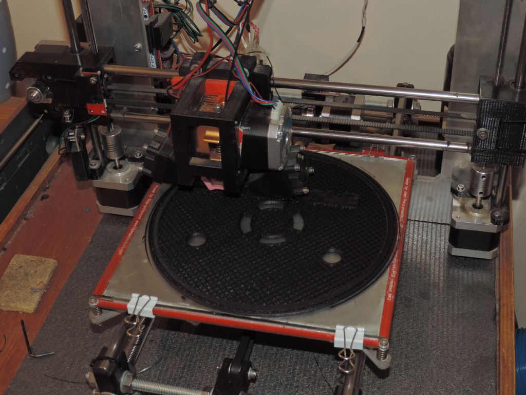
                      This part (photographed an hour ago) which is presently 5h 16m into an 8 1/2 hour print is 192mm diameter, so teh skirt is 202mm (and runs off the build plate at the front).

                      dscn9655.jpg

                      #467933
                      Enough!
                      Participant
                        @enough
                        Posted by Neil Wyatt on 28/04/2020 15:35:34:

                        My setup now actually places the home position just off the buildplate, a minor inconvenience when checking the z-height but a bonus as nozzle purges don't make a lump on the buildplate.

                        I'm curious about this since it was my (possibly quite wrong) belief that printers home the z-axis (after homing x and y using the limit switches) by reaching down and touching the build plate; then withdrawing a few steps and approaching slowly to confirm.

                        I don't see how it would do this if the x and Y homes are off the build plate. I presume it can be done, since you obviously have.

                        #467934
                        not done it yet
                        Participant
                          @notdoneityet

                          I don't see how it would do this if the x and Y homes are off the build plate. I presume it can be done, since you obviously have.

                          I’m sure mine comes down on the z axis until it hits the limit switch – the bed is levelled on that pisition, so it should make no odds where the home point is, in reality.

                          #467935
                          not done it yet
                          Participant
                            @notdoneityet

                            I don't see how it would do this if the x and Y homes are off the build plate. I presume it can be done, since you obviously have.

                            I’m sure mine comes down on the z axis until it hits the limit switch – the bed is levelled on that pisition, so it should make no odds where the home point is, in reality.

                            #467943
                            Enough!
                            Participant
                              @enough
                              Posted by not done it yet on 29/04/2020 18:54:10:

                              I don't see how it would do this if the x and Y homes are off the build plate. I presume it can be done, since you obviously have.

                              I’m sure mine comes down on the z axis until it hits the limit switch – the bed is levelled on that pisition, so it should make no odds where the home point is, in reality.

                              … er …. well …. so does mine now you come to mention it. I had this fixation that the z-axis worked differently to the others.

                              Put it down to age, addled brain and forced isolation.

                              #467955
                              Neil Wyatt
                              Moderator
                                @neilwyatt
                                Posted by Bandersnatch on 29/04/2020 18:42:59:

                                Posted by Neil Wyatt on 28/04/2020 15:35:34:

                                My setup now actually places the home position just off the buildplate, a minor inconvenience when checking the z-height but a bonus as nozzle purges don't make a lump on the buildplate.

                                I'm curious about this since it was my (possibly quite wrong) belief that printers home the z-axis (after homing x and y using the limit switches) by reaching down and touching the build plate; then withdrawing a few steps and approaching slowly to confirm.

                                I don't see how it would do this if the x and Y homes are off the build plate. I presume it can be done, since you obviously have.

                                No mine has a limit switch to one side, you set it to avoid the nozzle hitting the plate as the tips or build plate can be damaged.

                                That said, some printers have switch or capacitative sensors for automatic bed levelling, generally the contact type extends past the nozzle and retracts for printing.

                                Ah… just seen your second post!

                                Neil

                                #467996
                                Enough!
                                Participant
                                  @enough
                                  Posted by Neil Wyatt on 29/04/2020 20:23:23:

                                  Ah… just seen your second post!

                                  Wouldn't you know it …. just when you're locked in and can't get out to the opticians.

                                  I'll leave now.

                                  smiley

                                  #468045
                                  ega
                                  Participant
                                    @ega
                                    Posted by Neil Wyatt on 29/04/2020 17:05:14:

                                    Posted by ega on 28/04/2020 16:38:45:

                                    Neil:

                                    May I ask where you get your ground stainless rod, please?

                                    Just searched for 8mm stainless ground rod online, seems to be a speciality of 3D printer cnc specialists. Our usual suppliers only seem to do drawn rod.

                                    Neil

                                    Thanks. Just wondered if you had found a particularly helpful supplier.

                                    #468274
                                    Mark Simpson 1
                                    Participant
                                      @marksimpson1

                                      Neil.

                                      I too have the same printer as you, and won a few extra mm by putting a bigger piece of glass on the plate; you rarely print on the corners anyway it's mostly the skirt editing the machine bed size in Cura > Machine settings got the datum back onto the glass.

                                      I wonder if you had any success printing PETG? I've tried many combinations of settings and get rubbish results, I've now got a bin full of scrap and lost my original cura settings for PLA… I can print the CV19 headbands in PLA but dismal failure in the preferred PETG… I tried two different rolls so don't think it's the material.

                                      Thanks (in advance)
                                      Mark

                                      #468278
                                      not done it yet
                                      Participant
                                        @notdoneityet

                                        I wonder if you had any success printing PETG?

                                        Isn’t it an accepted fact that flexible filament is difficult, or even impossible, to use with a bourdon type feed?

                                        My Solvol, with a direct drive head, largely circumvents the issue of flexibility, I believe (not tried it yet as PLA is challenging enough for me at present🙂 ).

                                        #468279
                                        Joseph Noci 1
                                        Participant
                                          @josephnoci1

                                          Hi Neil,

                                          Finally done with all the current batch of collars, etc. Thoroughly overloaded on wildlife conflict stuff, so..back the the workshop and FINALLY back on my oddball 3D printer…

                                          Starting with the Z axis, which first start with the table and how its constructed. Can you explain you table construction a little please? There ais a flat 'plate' under the actual print surface I presume – Aluminium? and then is that reddish material a silicone flat rubber heater? Is that flat up against the surface below it, and is there some sort of heat insulator between? The I presume the print surface is a glass sheet – right against the heater – what thickness is the glass? I see spring clips holding the sandwich together – how well does tha sandwich maintain its thickness, ie, is there not a possibility of the Z gap to print head varying with heat, and time – do you use print head leveling and do you do that everytime before printing?

                                          Please..

                                          Joe

                                          gears and arms.jpg

                                          #468294
                                          Andrew Entwistle
                                          Participant
                                            @andrewentwistle

                                            Hi Joe,

                                            If the bed moves as the y-axis then its mass needs to be minimised for optimum speed without inducing ghosting artefacts from vibrations on deceleration of the bed. As a compromise it is usual to have an aluminium bed of a few mm thickness (with attached silicone heater) which may not be stiff enough to hold its flatness. This is where auto bed levelling comes in, in my case with a probe lowered in place by a servo that operates an opto interrupter switch. If starting from scratch I would prefer a core x-y configuration with a more substantial bed only moving in z. In this case the better rigidity means that levelling is a one-off setup (for a fixed bed surface).

                                            My preference for print surface is a PEI coated stainless steel sheet that attaches magnetically to the aluminium bed. This works without tricks for PETG and PLA. Prints can be easily released by flexing the plate. The plate can be swapped out for one with Kapton tape coating for printing ABS onto ABS slurry. Glass is also a very nice surface for printing ABS. Using auto bed levelling I can monitor the flatness and it is defined by the aluminium bed; the stainless sheet is pulled down flat to follow its profile to better than 0.05mm

                                            Cheers,

                                            Andrew.

                                            Edited By Andrew Entwistle on 01/05/2020 10:00:08

                                            #468305
                                            Andrew Entwistle
                                            Participant
                                              @andrewentwistle

                                              I only carry out Auto Mesh bed levelling if I know I have disturbed the printer, but I do home in Z onto the print surface at the start of each print.

                                              Some print beds have PCB track heaters, either clamped as a sandwich to glass, or bonded to the aluminium bed.

                                              Edited By Andrew Entwistle on 01/05/2020 10:33:59

                                              #468372
                                              Joseph Noci 1
                                              Participant
                                                @josephnoci1

                                                Thanks Andrew.

                                                I have a grasp of the type of setups used – been googling a lot of that when scheming how to do my Polar printer.

                                                I am just interested in Neil's setup because I know it works well – Neil gets good results, and the way he has it does not look complicated Stainless sheet with strange coatings, etc – all that kind of stuff is not easy to come by were I live! Ali sheet, glass, those are easy!

                                                Joe

                                                #468401
                                                Neil Wyatt
                                                Moderator
                                                  @neilwyatt
                                                  Posted by not done it yet on 01/05/2020 09:06:30:

                                                  I wonder if you had any success printing PETG?

                                                  Isn’t it an accepted fact that flexible filament is difficult, or even impossible, to use with a bourdon type feed?

                                                  My Solvol, with a direct drive head, largely circumvents the issue of flexibility, I believe (not tried it yet as PLA is challenging enough for me at present🙂 ).

                                                  PETG is challenging, but yes I can print it.

                                                  It's not a flexible filament though, that's TPU. With thin non bowden printer all it needs is a guide between the feed wheels and the heat brake. Having this little guide also makes changing filament of any kind easy.

                                                  Neil

                                                  #468403
                                                  Neil Wyatt
                                                  Moderator
                                                    @neilwyatt
                                                    Posted by Joseph Noci 1 on 01/05/2020 09:08:52:

                                                    Hi Neil,

                                                    Can you explain you table construction a little please? There ais a flat 'plate' under the actual print surface I presume – Aluminium? and then is that reddish material a silicone flat rubber heater? Is that flat up against the surface below it, and is there some sort of heat insulator between? The I presume the print surface is a glass sheet – right against the heater – what thickness is the glass? I see spring clips holding the sandwich together – how well does tha sandwich maintain its thickness, ie, is there not a possibility of the Z gap to print head varying with heat, and time – do you use print head leveling and do you do that everytime before printing?

                                                    Hi Joe, it's a triumph of 'just adequate' being 'plenty good enough'.

                                                    The base is an off the shelf standard PCB with a heater trace etched into it and a central thermistor. The thin aluminium spreads the heat. The build plate proper is a sheet of borosilicate glass to replace the original which was actually a tin sheet of mirrored glass which cracked and spalled off! The borosilicate (pyrex) is comparatively robust.

                                                    Levelling is manual with two fixed points at the rear and two adjustable ones at the front. You can also adjust by turning the two z-axes independently by hand (hold one still as the steppers act in synch!)

                                                    Best to set the two z-steppers first, against the fixed back of the bed – this avoids introducing hard to eliminate twist with the two adjustable corners. Printing a big circle (just initial layer) is the quickest and most accurate way to fine tune.

                                                    Yes, it is a fiddly as it sounds.

                                                    Once levelled, however, I find the only adjustment needed more often than once in a blue moon is the Z-home position as the nozzle wears or after a nozzle change.

                                                    #468443
                                                    Joseph Noci 1
                                                    Participant
                                                      @josephnoci1

                                                      Thanks Neil.

                                                      What sensor do you use for the auto-level process? And how does that process work on your printer? How many points ( a grid?) does the system check for height variation across the print platten?


                                                      Quite fun building this thing of mine – Of course , I believe I can do better than all the solutions out there, and proceed to waste a lot of time inventing the next answer to all problems….

                                                      So, while doing the Polar printer, I am also trying a DC motor worm-geared print head that is Induction heated, with no thermister sensor…

                                                      My aim is to fit the extruder head on the end of the SCARA arms, no Bowden tube, so the extruder has to be as light as possible, with as few wires as possible. Induction heating , if I get the concept to work reliably, will promote a light weight head.

                                                      Tests show some promise – I made some sample nozzles of 304 and 316 stainless steel, with a 10 turn coil around for the induction heater. The energy source is an 80 watt RF class E amplifier, driven by a 12 to 16MHz tuneable RF signal. The coil and nozzle are tuned to provide a matched load to the RF amp, when the nozzle is at 200degC . The frequency of the signal driving the amp changes from 12.2MHz when cold , to 15,8MHz when hot – this is changed in a closed control loop,  keeping max energy transfer to the load ( the nozzle..) . This is measured by a simple reflectometer ( SWR meter, for the Hams among us..) – when the ratio between reflected power and forward power to the load worsens, the frequency is changed to improve it. There is a sweet 'frequency' spot, which can be determined in a calibration cycle, at which the temperature is at set point. Then, keeping the frequency constant , if the nozzle heats more, the SWR degrades so reduce the amplifier output – the nozzle cools, and the SWR improves, until the curve goes the other way, where SWR degrades again, so increase the power till the SWR improves, etc – this provides SWR controlled temperature control, due to the curie effect of the heated nozzle.

                                                      The 304 grade nozzle gives the largest SWR change near 200 to 280deg C, so maybe the better alloy to continue test with. I would like to try some of the ferritic grades, but nothing in Namibia…

                                                      Probably going the be the most complicated 3D printer around, IF it actually gets to print anything!

                                                      Joe

                                                      Edited By Joseph Noci 1 on 01/05/2020 21:13:33

                                                    Viewing 25 posts - 1 through 25 (of 43 total)
                                                    • Please log in to reply to this topic. Registering is free and easy using the links on the menu at the top of this page.

                                                    Advert

                                                    Latest Replies

                                                    Viewing 25 topics - 1 through 25 (of 25 total)
                                                    Viewing 25 topics - 1 through 25 (of 25 total)

                                                    View full reply list.

                                                    Advert

                                                    Newsletter Sign-up