Impulse Drive Pendulum Clocks

Advert

Impulse Drive Pendulum Clocks

Home Forums Clocks and Scientific Instruments Impulse Drive Pendulum Clocks

Viewing 12 posts - 1 through 12 (of 12 total)
  • Author
    Posts
  • #242418
    James Alford
    Participant
      @jamesalford67616

      I have seen some pictures and some vidoes of clocks when the pendulum is kept swinging either by a combination of an electromagnet and permanent magnet at the base of the pendulum or by a solenoid pushing the pendulum. However, I cannot see any other method of driving the clock.

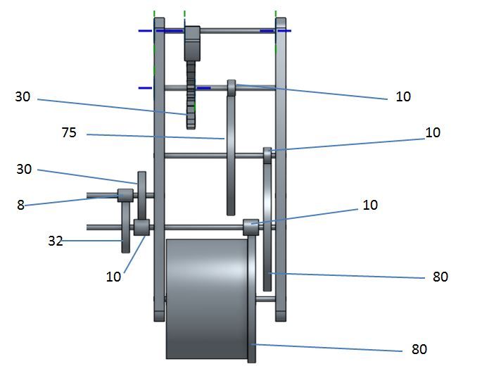
      Am I right in thinking that with such clocks, the movement is driven by the pendulum, rather than the movement driving the pendulum as it does in most clocks? If that is so, would such a mechanism as my basic design below be likely to run if I were to convert the pendulum to an impulse drive and dispense with the weights?

      Or am I being completely dense…………

      side view.jpg

      Regards,

      James.


      Edited By James Alford on 12/06/2016 09:25:15

      Advert
      #3730
      James Alford
      Participant
        @jamesalford67616

        How do they work?

        #242421
        Michael Gilligan
        Participant
          @michaelgilligan61133

          James,

          For starters … Read about the 'Hipp Toggle'

          MichaelG.

          #242424
          James Alford
          Participant
            @jamesalford67616

            Michael,

            Thank you. A quick look at that made me realise that that is the type of clock that we used to have in the telephone exchanges in which I used to work as an engineer! They always intrigued me.

            I shall read in more detail.

            James.

            #242435
            peak4
            Participant
              @peak4
              Posted by James Alford on 12/06/2016 10:24:28:

              Michael,

              Thank you. A quick look at that made me realise that that is the type of clock that we used to have in the telephone exchanges in which I used to work as an engineer! They always intrigued me.

              I shall read in more detail.

              James.

              Here you go. I have one hanging up in my dining room. Runs fine off 12v; it doesn't need the full -50v.

              Clock No.36

              #242439
              Howi
              Participant
                @howi

                Ah! The memories……them were the good old days, then along came System X and System Y and the engineers faded into insignificance.

                At one time the TO's (tech officers) were told they would be relinquishing their (extensive) toolkits in exchange for an Alsation guard dog and boxes of dog food..

                Asking the question why? We were told our duty was to maintain(feed) the dog.

                But why the dog we asked?

                To guard the equipment and prevent the TO from touching it.

                This was after a study found that if you prevented as much interference by the engineers as possible, the equipment was much more reliable.

                I got out just at the right time!

                #242456
                Bazyle
                Participant
                  @bazyle

                  For the pendulum to drive the time chain the design of the escapement has to change, but you will see that when you examine the Hipp details.

                  #242795
                  modeng2000
                  Participant
                    @modeng2000

                    I made the ME Jubilee clock quite some time ago and it has been mothballed for a while as other things got done. It kept good time and was a nice piece of furniture. However now it is going again I realise how noisy it is and am thinking of converting it to the Hipp method of impulsing the pendulum.

                    Are there available any drawings of this type of drive? I am interested in a few basic dimensions although I might be able to guestimate from the published photographs.

                    John

                    #242800
                    duncan webster 1
                    Participant
                      @duncanwebster1
                      Posted by modeng2000 on 14/06/2016 15:34:23:

                      I made the ME Jubilee clock quite some time ago and it has been mothballed for a while as other things got done. It kept good time and was a nice piece of furniture. However now it is going again I realise how noisy it is and am thinking of converting it to the Hipp method of impulsing the pendulum.

                      Are there available any drawings of this type of drive? I am interested in a few basic dimensions although I might be able to guestimate from the published photographs.

                      John

                      ME Jubilee clock uses the Hipp method of working out when it needs an impuse, but the has a noisy electromechanical method of impulsing the pendulum. My clock has 2 opto switches to work out when it needs an impulse. One at the extreme of travel cancels the next impulse, one at the mid point sets the point at which it impulses. It's a sort of inverse Hipp, it gets an impulse every swing unless the amplitude is too high, whereas the original doesn't get an impulse unless the amplitude is too low. The actual impulse is provided by an electromagnet, made from the coils of old 24v relays (running on much lower voltage), acting on a steel armature on the bottom of the pendulum. The logic is done by PICs, which I wouldn't do again, but the softawre would easily transpose to an Arduino. It should be possible to use the ME Hipp thing to drive an electromagnet like mine.

                      It's been running for a number of years now without any attention. The time display is via a Gents alternating polarity slave, but I have made a slave from a stepper motor and some off the shelf gears.

                      #242802
                      modeng2000
                      Participant
                        @modeng2000

                        Thanks Duncan. I thought I'd like to try the impulse method as in this link http://www.britishtelephones.com/clocks/clock36.htm from peak4

                        #242807
                        Ajohnw
                        Participant
                          @ajohnw51620

                          My clock is held up on working out gear trains for a while so got side tracked. If I make one I want something that is pretty precise. To me that means no need to adjust until the clocks change and minute error over that period is ok.

                          The best option as I see it is an electric remontoire of some sort. There is a catch though. Most methods have some sort of error so the the re energising interval can only be so long. If it's pretty short there will be some small short term variation at say the seconds level but this will be evened out by the remontoire being "rewound" and also taken care of when the rate is adjusted.

                          With this set up the remontoire is driving the clock and can be put in different places but the further away it is from the pendulum the more scope there is for friction variations.

                          For an electric impulse I would be tempted to look at either precise crystal oscillators or a radio derived time signal from an atomic clock but the same idea of keeping the impulse rate interval short could be used with the Hipp arrangement. I have been wondering about dismantling a relay to get a suitable low power solenoid for that but it's rather hard to decide just how much power is needed. The design i have seen uses a pretty hefty one and I have no interest in wiring to the mains or needing to fit batteries often.

                          A spring driven clock where the spring rewinds the remontoire can also work out but the interval it takes to actually "rewind" it will vary as the spring winds down. An answer to that might be to use a weight and rewind that periodically with electronics. So far that looks to be the most sensible answer but can I get it to rewind at night when I am asleep and in bed – maybe.

                          I don't want to hear a motor whirring away when it rewinds.

                          John

                          #242840
                          James Alford
                          Participant
                            @jamesalford67616

                            Some interesting replies and ideas here: thank you. I have also found this article which appears to cover much of what I had been thinking about. I have not read it in depth yet, but it seems good. It appears to use a pendulum that is kept in motion by an electromagnet to pull the clcok movement, rather than just regulate it. A prgrammed chip controls the impulse to the solenoid.

                            **LINK**

                            Regards,

                            James.

                          Viewing 12 posts - 1 through 12 (of 12 total)
                          • Please log in to reply to this topic. Registering is free and easy using the links on the menu at the top of this page.

                          Advert

                          Latest Replies

                          Viewing 25 topics - 1 through 25 (of 25 total)
                          Viewing 25 topics - 1 through 25 (of 25 total)

                          View full reply list.

                          Advert

                          Newsletter Sign-up