Improved Experimental Pendulum

Advert

Improved Experimental Pendulum

Home Forums Clocks and Scientific Instruments Improved Experimental Pendulum

Viewing 10 posts - 201 through 210 (of 210 total)
  • Author
    Posts
  • #647199
    Nick Wheeler
    Participant
      @nickwheeler

      Perhaps the clock is alarmed by your tidiness?

      Advert
      #647206
      Bazyle
      Participant
        @bazyle

        Seems like a software problem. Is there a subroutine that keeps creating new local variables until it runs out of memory? We had a problem with a product some 20 years ago where the garbage collection happily worked in the background until a customer decided to change channel every couple of seconds for 39 minutes thus preventing the background tasks and running out of memory. Our test team were not happy having to prove the fix worked.

        #647352
        SillyOldDuffer
        Moderator
          @sillyoldduffer

          I agree software is the likely cause. I've confirmed a few things it's not:

          • Pendulum period as measured by the Arduino is steady, apart from the expected temperature and pressure changes that don't explain a constant drift. Nor is the drift explained by the average rise UK in temperature as summer approached.
          • The going increments correctly, so the clock should average UTC – unlikely to be spot on, but always nearby.
          • NTP on the Raspberry is OK (usually within 30ms of GPS) Like the pendulum, NTP varies around average UTC, and doesn't drift.
          • Not running out of memory, or at least that's extremely unlikely

          Related to running out of memory is integer or buffer overflow, which is possible. Still looking, but I've not found any candidates

          Also under investigation is USB/serial comms delay. Not looking likely, as it seems to be fairly constant, and I can't think of a way it would cause constant drift.

          I'm probably missing something obvious. Meanwhile, I upgraded the software last night. Not expecting much because it only removes some dead code and fixes a few buglets. Having to let code run for a day or two to confirm it's working properly doesn't help. I share your test team's pain!

          sad

          Dave

          I

          #649510
          SillyOldDuffer
          Moderator
            @sillyoldduffer

            I confess to procrastination. Fearful of what looking at my iffy clock is doing, I've left it alone for 8 days with compensation switched on. Reason for my lack of moral fibre is I've run out of ideas. I don't mind problems I can solve, but not having a clue about what to try next is demoralising! The forum ought to have a Topic where members suffering the trauma of yet another workshop disaster can go for tea and sympathy.

            Anyway, a short power-cut this morning stopped the clock, so I girded my loins, gritted my teeth, stiffened my lip, thought of England, and downloaded the log.

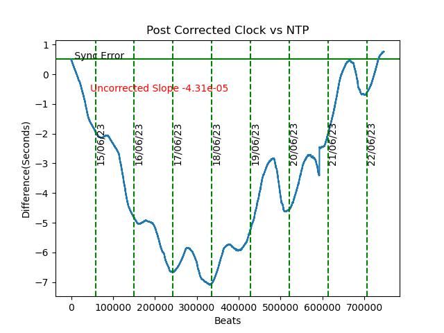
            Results not too bad. After 8 days my clock was 0.51 seconds fast when the power-cut stopped it. Not truly wonderful because as this graph shows it wandered on the way. The blue line should follow the green line:

            1606postcorrected.jpeg

            Looks as if the compensation isn't quite right, because the wander shows temperature bumps. I'm not too upset because this new graph shows a reason. It takes the clock longer that I expected to gather enough pressure and temperature data.

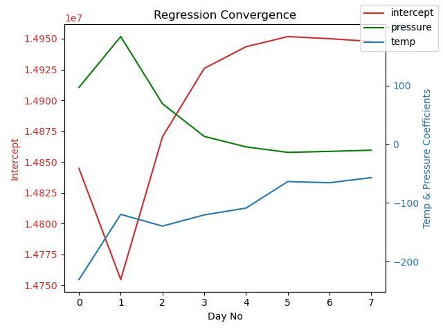
            1306regrconv.jpeg

            The graph plots the three factors used to compensate the clock. The red line is the intercept, and the green and red lines are the temperature and pressure coefficients. The three lines should become parallel, and it can be seen that they don't approach that until day 5. And the regression results are wildly wrong during the first 3 days.

            Explains at least part of the wander because the clock can't keep good time until the compensation coefficients are correct.

            Pity the power failed. After 8 days the lines still aren't completely parallel, which means more temperature and pressure data is needed. 746758 samples weren't enough!

            I'm going to restart the clock with the latest coefficients and let it run for as long as possible, thunderstorms permitting, to see if the wandering is reduced. Meanwhile, with morale restored somewhat, I'll make a start on building the vacuum containment.

            Dave

            #650378
            SillyOldDuffer
            Moderator
              @sillyoldduffer

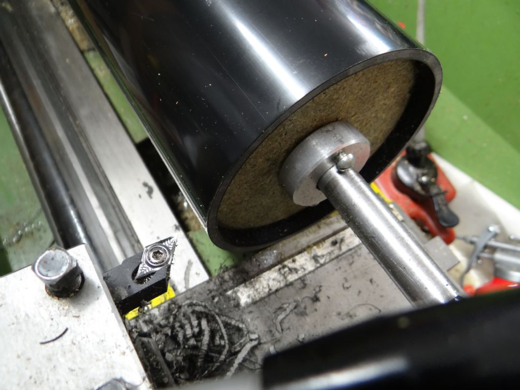
              The vacuum tube (a length of 4" diameter PVC soil pipe) is the biggest item I've turned on my lathe.

              Only needed to put it in the lathe to turn the rough sawn end of the PVC pipe flat, and far more work went into holding the pipe than to cutting it. Apart from being close to the maximum length that will fit my lathe without taking the tailstock off, PVC pipe is bendy, prone to dig-ins, and liable to melt. Needs to be held firmly whilst being attacked with a sharp cutter.

              A sharp carbide insert at low RPM and low depth of cut worked better than HSS. I'm not convinced either is a good choice for turning PVC, but the insert got the job done.

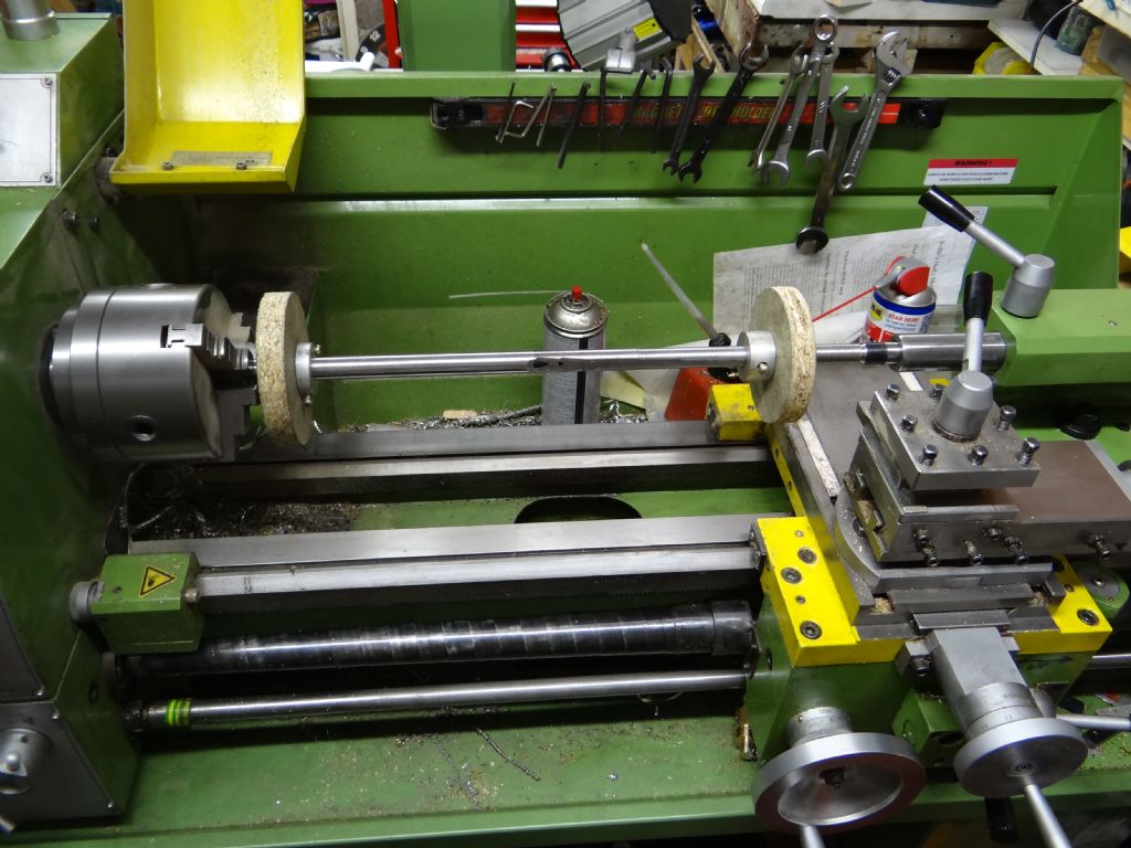
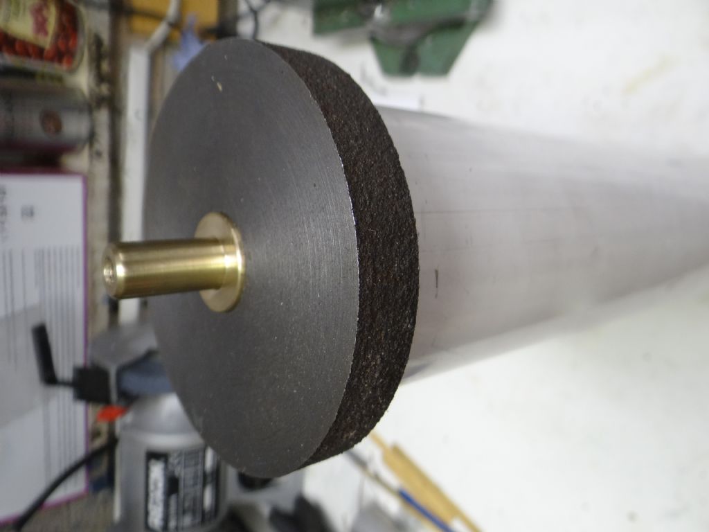
              Took me about 10 hours to design and make a mandrel:

              dsc06768.jpg

              It's a length of steel gas-pipe with 4 tapped collars holding a pair of chipboard wheels turned to fit the PVC pipe. . One end is held and spun by the 3-jaw, the other is supported by a dead-centre.

              Sod's Law ensured that my live centres are either just too big or just too small to fit gas-pipe, but there's just enough room for the saddle at the PVC pipe end. That was lucky, because I expected to have to take the swarf guard off the lead-screw to get enough travel.

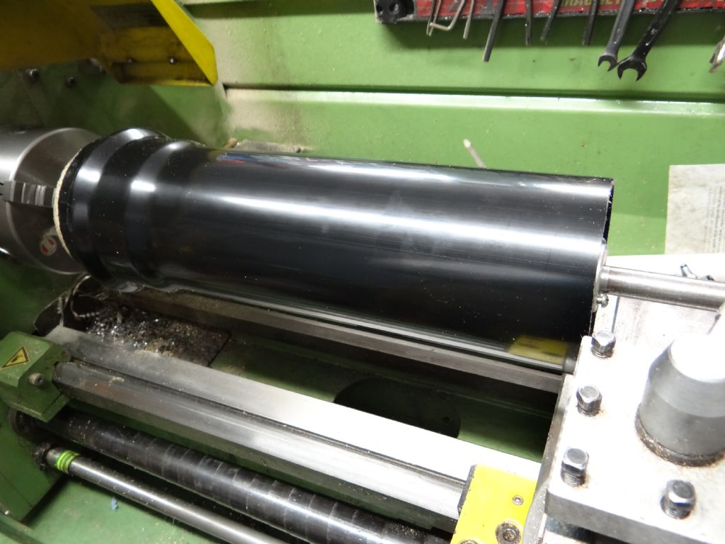
              dsc06769.jpg

              After all the preparation the actual cut was an anti-climax. The HSS tool was rejected after a couple of minutes of nearly cutting, short pause whilst I switched to carbide, and then the real cut took about 30 seconds.

              dsc06771.jpg

              A problem I hadn't anticipated was cleaning the pipe. Wiping off attracted a mass of sawdust and cat-hair due to static electricity. The amount of sawdust made me wish I'd worn a mask: the air was still full of dust at least 90 minutes after I'd made the wooden discs.

              Next step is to make or buy a bulkhead penetrator for the wiring. Once that's available, I can take the clock apart and drill the base to fit the penetrator and the vacuum tubing.

              Although the pendulum, electronics and software aren't really working well enough to justify running the clock in a vacuum, I feel the need to get on with the mechanicals. Trouble is testing the software takes at least a week because the clock achieves accuracy by learning how to compensate for temperature and pressure changes. As Mother Nature is fickle and slow, she takes a long time to provide all the combinations. It's caused long delays.

              With hindsight, might be quicker to fit the vacuum containment and run the pendulum at a series of fixed low pressures. Running in a vacuum would also validate my assumption that the temperature-pressure formula derived by analysing normal weather is OK for a pumped low pressure. I'm fairly confident but nothing about this project has been straightforward…

              Dave


              Edited By SillyOldDuffer on 29/06/2023 18:09:20

              #652998
              SillyOldDuffer
              Moderator
                @sillyoldduffer

                I gave up searching for the lost end-cap and made a new one. Luckily there was a suitable lump of cast-iron in my junk box left over from making a chuck backplate.

                dsc06805.jpg

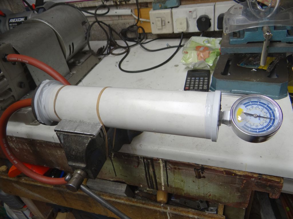
                Armed with a length of PVC drainpipe, two end-caps, nozzle, and a vacuum gauge I was able to test my vacuum pump.

                dsc06808.jpg

                Result: -490mB below atmospheric.

                Mild disappointment: I was hoping for -600mB, (+12mB here at the moment.)

                Not given up yet. When the end-caps are only held on by air-pressure, the pump only manages to get down to -200mB, even though it's not obvious there's leakage. However, wrapping the Aluminium end with electrical tape almost immediately doubled the vacuum to about -400mB, and then taping the cast-iron end got me down to -490mB.

                At this point I noticed a silly mistake! The brass nozzle, which is a push fit through the cast-iron cap, is made the wrong way round. The sealing flange is on the inside and it has to be on the outside. With luck fixing this will improve the vacuum. Then I can try sealants.

                Worry beads time: it appears that even a miniscule leak quickly destroys a deep vacuum. My next problem is to hold a vacuum for years without further pumping, and I doubt my PVC soil pipe design is up to it. However, if all else fails, I've proved I can get below the lowest ever natural air-pressure recorded, which was -130mB inside a super-typhoon near Guam. If I run the pendulum inside its tube at -200mB, it should be immune to natural barometric changes.

                Dave

                Edited By SillyOldDuffer on 20/07/2023 14:45:27

                #655816
                S K
                Participant
                  @sk20060

                  perfectca.jpeg

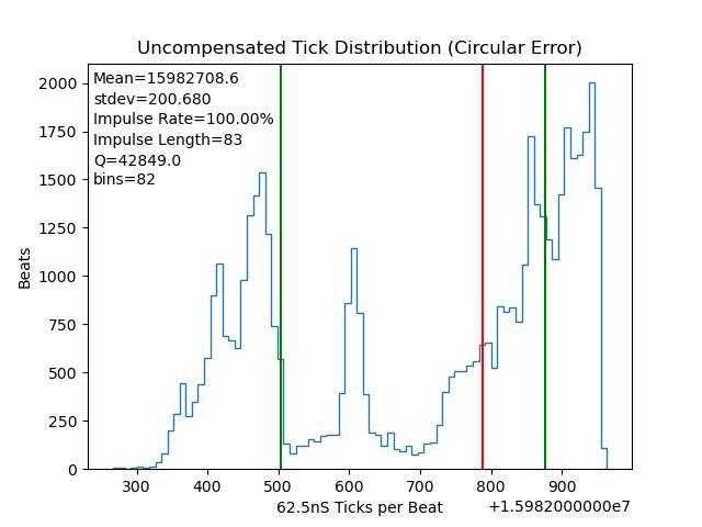
                  SOD: Following the discussion regarding Q in a different recent thread: If you are using this data to compute it, caution would be advised. The distribution is not remotely Gaussian, it's bicameral (or even tricameral?). Therefore, while a calculation of standard deviation is still mathematically possible, I do not think it will be particularly meaningful in the context of a calculation of Q for a system where a normal distribution is expected.

                  My advice would be to verify the accuracy of your calculations of Q using the un-impulsed decay method before torturing yourself trying to understand how it wanders.

                  I also suggest your focus should be on why the distribution is so dramatically non-Gaussian, especially why there are two huge lobes some distance apart. I'd bet you would feel it a breakthrough if you can figure out why.

                  #655821
                  SillyOldDuffer
                  Moderator
                    @sillyoldduffer
                    Posted by S K on 09/08/2023 15:40:01:

                    SOD: Following the discussion regarding Q in a different recent thread: If you are using this data to compute it, caution would be advised. The distribution is not remotely Gaussian, …

                    Correct, well spotted. Not sure which test run that distribution came from, but I've had several where the graph isn't normal. The graph indicates a fault, either with the pendulum or the suspension or the IR sensor. Consequently the Q calculation is misleading at best.

                    I tested the first version of the pendulum in many different circumstances, and found it to be sensitive to vibration, temperature, pressure, humidity, impulse power, impulse timing and sunlight. Also, the experimental rod and suspension were capable of much weirdness, such as the rod vibrating and the bob swinging in ellipses.

                    The Improved Pendulum being discussed in this thread fixes all that, I hope! The resulting dataset is a normal distribution, or close to it, so the Q calculation is valid. Assuming I got the sums right that is: I'm terrible at maths!

                    Your observations are much appreciated. I look at the graphs and numbers carefully but it's easy to miss clues and mistakes and jump to wrong conclusions. More eyes-on the better!

                    Dave

                    Dave

                    #659388
                    SillyOldDuffer
                    Moderator
                      @sillyoldduffer

                      An interim progress report, and some clues about what's going wrong/ Maybe.

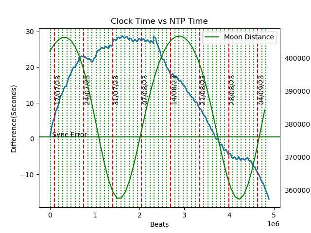
                      Clock's been running for nearly 53 days and is 16 seconds slow at the moment. The rate is wandering:

                      230906clockvsntp.jpeg

                      Looking at myclock vs reality(NTP), I wondered if I was seeing the start of a 40 day cycle. No idea if such a thing exists in nature so I added kilometres from the Moon in a forlorn hope the curves would show an astronomical influence. Nope, and I didn't really expect it to. Don't believe in star signs either.

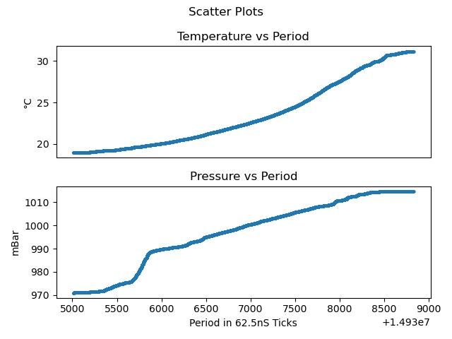
                      The wander may be due to a different problem. The clock assumes that its pressure and temperature correction factors are both straight-line graphs, i.e. the relationship between period and temperature/pressure is accurately predictable. These graphs aren't straight. Temperature shows a distinct bad news curve and pressure only becomes fairly straight after starting with an anomalous kink:

                      230906scatterptpp.jpeg

                      Maybe the sensors are faulty – the device is a clone, not made by Bosch who invented it.

                      Dave

                      #675513
                      SillyOldDuffer
                      Moderator
                        @sillyoldduffer

                        Not been idle with my clock.  After moving it to a a dark place to minimise vibration and sunshine, I allowed to run without compensation to see if it’s wandering rate was caused by some sort of compensation error. Appears to be so, but the reason remains unclear.

                        In the graph, the blue line is the uncompensated clock, and if zoomed in on closely, it shows variations due to temperature.   (The graph scale hides detail).

                        The orange line is clock time compensated for temperature only – nearly straight, with slight wiggles due to uncompensated air pressure variations.  The straight line is encouraging, but not that constant down slope. Should be horizontal.  The cause unknown, maybe my shaky maths is missing something.

                        DRIFT

                        Compensating for the constant error hides the problem, and the green line keeps excellent time.  As having the clock apply a second compensation to fix the orange slope is a bodge, I need to understand what root cause is.  At the moment, I’m baffled, yet again!

                        Dave


                      Viewing 10 posts - 201 through 210 (of 210 total)
                      • Please log in to reply to this topic. Registering is free and easy using the links on the menu at the top of this page.

                      Advert

                      Latest Replies

                      Viewing 25 topics - 1 through 25 (of 25 total)
                      Viewing 25 topics - 1 through 25 (of 25 total)

                      View full reply list.

                      Advert

                      Newsletter Sign-up