you could put some small variable resistance in line with your magnet coil, then fine tune the impulse with that
Except the clock is remote controlled! What I actually did was go to the program and alter the counter/timer pre-scaler to provide 4x more precision. It's a single bit in TCCR2B:
TCCR2B |= (1<<CS22)|(1<<CS21)|(0<<CS20);
So instead of a choice of 3 impulse lengths between 0.001088 and 0.00128s I have 12, which should be good enough.
I intend to try a regulator where the bob is impulsed slightly too lightly on every beat, so it gradually loses amplitude, but is topped when it drops below a certain threshold. The topping up can be finely adjusted to minimise shocking the bob.
Next job is to check last nights run. I deliberately set the impulse high and now have to tune it down to find the minimum constant impulse that's not quite enough to keep the pendulum swinging permanently.
I've also implemented John Haine's self-start, which pulses a stopped bob 'n' times at the right frequency to get it swinging. Moving the electromagnet closer to the bob also worked, but I'm not quite close enough because it fails to grab the bob about 1 in 15. John's method is better for another reason – it swings the bob gently compared with a violent grab/release after which the pendulum takes at least 10 minutes to settle.
Today's worry is whether there will be enough room for the vacuum pipe work as well as an AT Mega under the base. Hoping to get a battery in there too!
During the day, I connect the clock (which is on my dining table so I can fiddle with it), to my workstation computer, making it easy to change the software. At night, I connect it to a RaspberryPi 3b, which wastes much less electricity and can be left running all the time. The clock failed to self-start on the Pi, odd because it worked before. Turned out to be due to me using a different USB cable: presumably the wires inside it are too thin and the volts drop enough to prevent sufficient amps reaching the magnet. Swapping the cable fixed it.
Lesson learned. not only does the amount of power actually available from a USB socket vary, but not all USB cables are equal!
Good result from last night's run:
Periods (in 62.5nS ticks): min 14914516.0 mean=14949452.289 max=15017427.0
dev = 3586.463 ticks
Clock Mean Period = 0.934341s
Actual Mean Period = 0:00:00.934465
std = 0.224us
Q = 7048
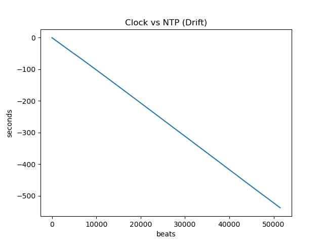
The uncompensated clock ran nearly ten minutes slow after 13 hours, but the drift is constant, trivial to compensate, this lovely straight line graph:
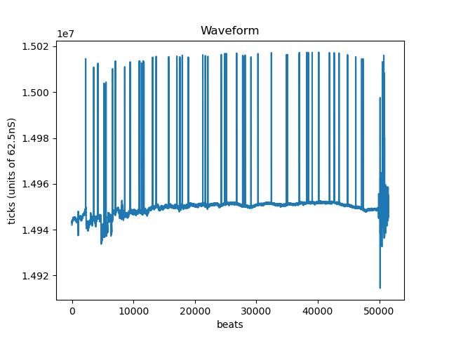
I've sussed out what's causing the comb on the waveform graph:
I noticed the comb peaks follow the true waveform and seem to be the same size. They are! The raw data shows they are close to 65536 above normal, 2^16, which happens to be the value added when the program tests for a near miss counter overflow:
// Correct if just missed an overflow
if (TIFR1 & bit(TOV1) && pendulumCountAtEventEnd < 128) {
pendulumOverFlowCount++;
}
I copied the code from my hero Nick Gammon, but have always been suspicious of it. I believe it's meant to deal with the counter overflowing at about the same time a pendulum event is received. I shall have to study the datasheet again. Although the comb looks bad, it doesn't matter much in practice. Determined to understand and fix it though.
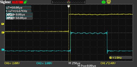
Another potential cause of noise on the pendulum is under investigation. It's the delay between the microcontroller detecting the bob and firing the electromagnet. I wondered how big the delay is, and if it varies much. This is typical:
Pendulum in yellow, magnet power in blue. The electromagnet is energised 60 microseconds after the bob breaks the IR beam. My test sample is very small, about 30 example, but the 60uS delay doesn't seem to vary. The main thing that would delay the magnet further is the clock receiving a command just before the beam is broken. Not likely because commands are sent at start of run to configure the clock and shouldn't be necessary after it's set.
Does anyone know how long a mechanical impulse takes between trigger and energy reaching the pendulum? It's not instantaneous.
I guess several tens of milliseconds in a Shortt Synchronome where the second pendulum operates a ratchet wheel, that releases a gravity lever dropping a small weight on the pendulum, operating a mechanical electric switch on the way. The switch releases another gravity lever that drops a weight on the first pendulum. Much slower than 60uS I suggest, plus variation due to the switch contacts, inertia and friction.
However I suppose the delay, whether mechanical or electronic, doesn't matter provided it's always the same-ish.
Great progress [again] Dave, but I wouldn’t worry too much about trying to compare your impulse-delay with that of the Shortt/ Synchronome … because that one only occurs once every [nominal] 30seconds, and yours is more ‘agile’
Fixing the electronic mistakes took most of Sunday afternoon and didn't work when reconnected to the clock, so lashings of despair. Another silly mistake.
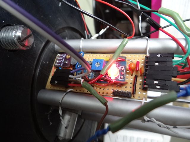
I'm not happy with the board – the layout was flawed, before I messed up! Had to mount the pressure/temperature module close to the switching transistor, not far from the cast-iron base, comparator chip, two LEDs, and the electromagnet coil. These the main sources of heat inside the vacuum containment, and may cause trouble.
A test run with the pressure/temperature module showed it works, but the log contains a high rate of false break readings, due to the beat counter occasionally triggering on both rising and falling edges. Not sure what causes this. As the input waveform is clean, it may be software: reading the pressure/temperature module, or maybe the extra time spent transmitting their numbers to the raspberryPi (which logs them).
Previously I was going to attach the electronics to the sensor chariot. It's easier to tie it to the pillars:
Didn't bother to tidy-up the wiring: saving that joy until I have a neat way of getting it through an airtight seal to the microcontroller under the base.
A few more changes:
Removed old code from previous experiments.
Pendulum now only impulsed when amplitude drops below a threshold. (The threshold is set experimentally and is probably too high. The impulse is also set experimentally, currently so an impulse is issued every other beat or two.
Reduced the number of self-start beats from 20 to 6. 20 crash the bob into the electromagnet.
Vacuum parts have started arriving, so I'm adding them to the model. Or would if I could remember how to do pipes in Solid Edge. Fitting the vacuum stuff is going to be fiddly – tight space.
Pleased to report, fingers crossed, that I've fixed an intermittent problem that's been annoying me for ages. It's that,rarely and apparently randomly, the clock registered a double beat. The false beat occurred on the FALLING edge of the beam break, when the microcontroller was programmed to repond only to RISING edges. Should be impossible, and I've been chasing all manner of esoteric and unlikely causes – many hours wasted.
Seems the actual cause was electrical noise on the input. Microcontroller inputs are vulnerable because they're high-impedance, making it possible for them to pick up glitches on long wires, or even from adjacent pins. The cure is to tie the input either HIGH or LOW with a resistor, about 10kΩ. It stops static and soaks up short spikes. Looking very good so far, zero false triggers in over 12 hours.
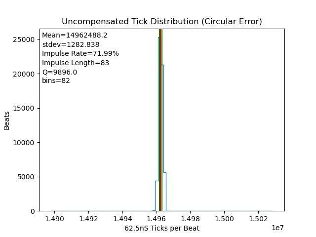
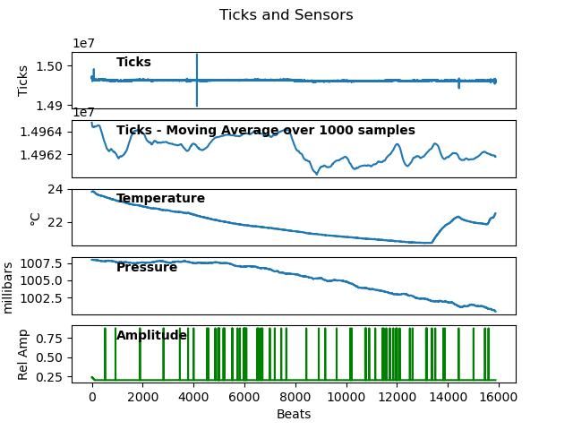
At the moment I'm running the pendulum uncompensated to determine it's characteristics. Nice straight line on the drift graph, and period only varies up to 80 microseconds per beat, much better than the Mk 1 clock, with a sharp evenly balanced distribution, hurrah!
Annoyingly, the good weather is failing to provide the variety of big temperature and air pressure changes needed to calibrate the pendulum: correlations are identified, but not strongly, meaning compensation values based on them won't cover winter and summer confidently.
The spiky green graph shows something is still wrong with the amplitude code or electronics. (I hoped the resistor would fix it, nope!) Even though the error rate is only 0.5%, and the affect of each error on the pendulum trivial, I want to fix it.
Comparing last night's run with actual time this morning showed the the clock should be set to an average period of 0.935266s rather than 0.924012s. Period was set to 0.935266s and the clock reset to UTC this morning. If that works, the clock should run close to UTC, but is still uncompensated. However, weather permitting, it will collect enough tempertature and pressure changes to enable compensation.
Progress is promising enough for me to tackle the vacuum containment problem, difficult enough for it to be worth it's own thread. The parts needed to plumb it have started to arrive.
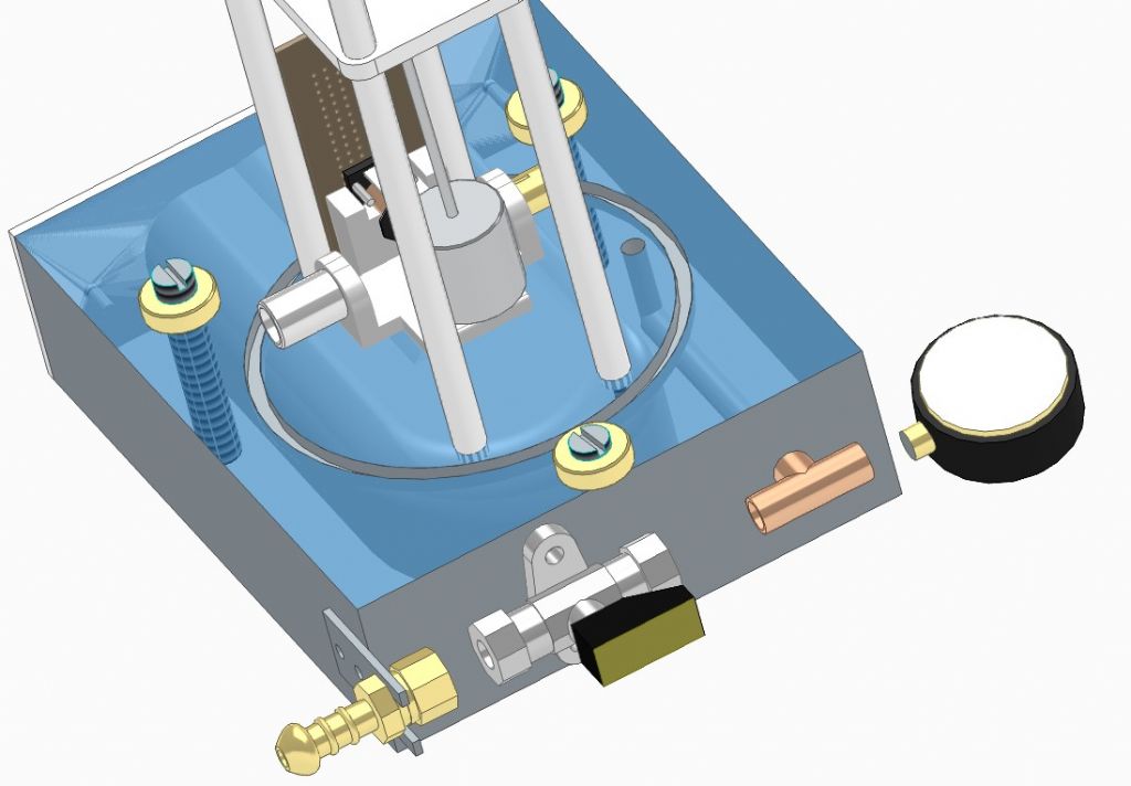
First attempt at plumbing was this:
Rubber hose from vacuum pump attaches to a nozzle connected to a valve, connected to T-coupler. Vacuum gauge on the end. Unfortunately, this configuration requires a ⌀ 6-8mm hole 100mm deep to be drilled accurately straight into the block. If it drifts, there's a high risk it will break out into the lower cavity.
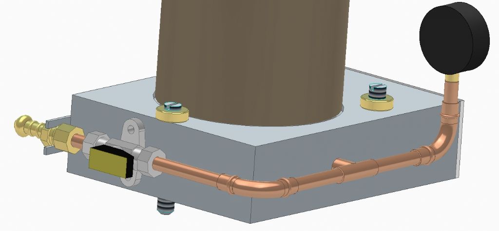
Second attempt avoids the need for deep drilling, but more pipe and joints. The vacuum gauge can be upright at the front:
The more I think about how to contain the vacuum, the more difficult is seems. I'm after a deep vacuum, and yonks ago Roger Atkinson said of my Edwardes EB3A pump "Specification seems to be 26" Hg / 133mB", about 86% vacuum. Not bad for a home clock, but ideally the vacuum has to be held steady for years. The container holds about 2 litres of nothing, so a leak of only 1cc air per day is cause for concern.
Leaks are less worrying if the pump is in poor condition and can't get that low a vacuum, but then the clock won't achieve it's best.
You could connect a large reservoir, like an old gas cylinder, to make the volume larger. It could be 30 ft away just as far as you can get a single copper pipe without joints.
You could connect a large reservoir, like an old gas cylinder, to make the volume larger…
Good idea, though I am trying to keep the clock small!
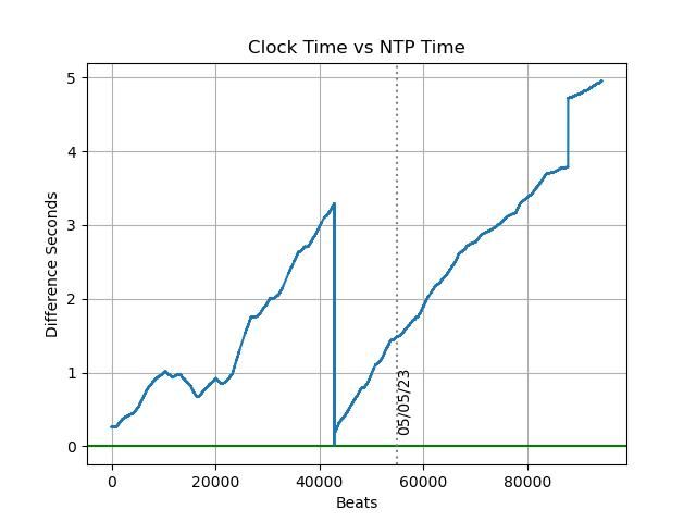
This morning's results are disappointing – looks like drift correction isn't working, possible because I 'improved' the code. The slope after correction last night is much the same.
The sharp drop down to zero before midnight is me resetting the clock to UTC. The 1 second leap this morning, right of graph, was due to cat jumping on the table. Cats and clocks aren't a happy combination.
My dining table being a poor platform, I moved the clock to a solid window-sill and have left it running to see how it performs undisturbed.
Meanwhile, I thought it would be useful to test the clock's software and measurement system with a perfect pendulum. The closest I can get to perfect pendulum is extremely good – it's the seconds pulse output of a GPS module, accurate within about 45nS.
I connected GPS pulses to my clock's pendulum input to see:
how stable the microcontroller's ceramic resonator is, not expecting much.
how well the clock beaten with a perfect pendulum keeps time compared with NTP.
how much the transfer time over USB from clock to Raspberry Pi varies.
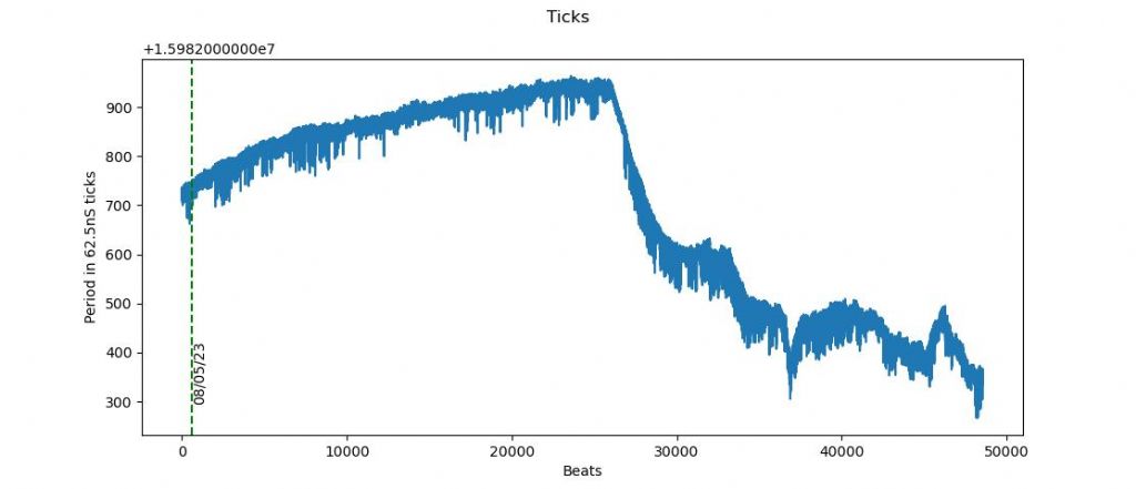
Stability of the ceramic resonator is poor, varying by about 38 microseconds over 13 hours. Most of the swing is due to temperature change, but stability between cycles is also poor, varying by about 1.23 microseconds on each beat. The nominal frequency of the resonator is 16MHz, its mean frequency in this run was 15.982708MHz
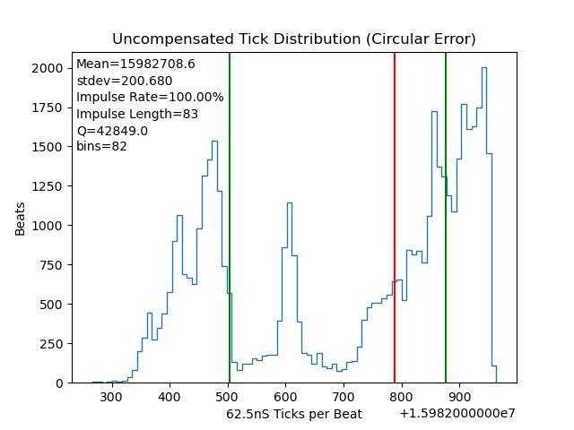
The weak performance of the resonator also shows up in the dispersion graph below. The graph should be a bell curve symmetric about the mean, and it's mangled. As the GPS pulse is near perfect, the mangling is caused by the resonator mismeasuring it, rather like checking gauge blocks with a 6" rule.
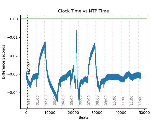
In this run the clock finished at 2023-05-08 13:19:00.0 whilst NTP reported 2023-05-08 13:19:00.031074, an error of 31.1mS Actually better than that because the synchronisation error (setting the Clock to NTP) was wrong by 0.030496s, making the actual error at the end of 578 microseconds.
However, graphing clock against NTP shows NTP bounces about!
Although NTP is never more than 30mS wrong, and is mostly closer, the graph shows each measurement varies by about 2.5mS. Part of the jitter is due to variations in transfer time – how long it takes the clock to resister a beat, assemble logging data, put the data on the line, and then for the Raspberry Pi to receive, decode and timestamp the data. More work needed, but transfer time appears to be fairly constant.
In short, although the clock and measurement system both work correctly, hurrah, feeding them a near perfect pendulum shows plenty of room for improvement! If my pendulum runs really well in a vacuum, I may find the measurement system needs to be updated. Fairly obvious steps include GPS disciplining NTP on the Raspberry Pi, and registering beats by signalling the event from clock to Raspberry with IO pins rather than USB serial.
Every step forward is harder to make, and the project is endless…
I take it you get NTP over the internet. is that cable modem, landline or mobile? You might like to run a parallel ping test to see how that is varying with your NTP data. The internet was never designed to send time critical data and is only kept vaguely in line because gamers whine so much about ping times,
edit – you could also mess your head up by comparing NTP from different servers, and mobile v other modem.
Dave, it's beginning to look as if the electronics measuring your clock's performance are possibly less accurate than your clock, making them unfit for purpose.
I take it you get NTP over the internet. is that cable modem, landline or mobile? You might like to run a parallel ping test to see how that is varying with your NTP data. The internet was never designed to send time critical data and is only kept vaguely in line because gamers whine so much about ping times,
edit – you could also mess your head up by comparing NTP from different servers, and mobile v other modem.
…
Yes, NTP over the internet, a deep subject in itself! How vague internet time is considered to be is relative! It's much better than most clocks.
The protocol works in a hierarchy, where Stratum 0 is a server connected directly to an atomic clock. These update a large number of nearby Stratum 1 servers, which in turn update Stratum 2 servers, which update more distant Stratum 3 servers on the internet. Each level is less accurate than the one above, but the protocol minimises this by constantly exchanging network latency timings to decide which of many servers are currently providing the most accurate time; the system automatically adapts to network performance.
Typically, an NTP time server on the internet available to Joe Public, is better than 10mS of UTC.
Accuracy suffers when connected to an ADSL consumer like me, but should still always be within 100mS of UTC. In my case, a further loss of accuracy occurs because my Raspberry Pi logger is WiFi connected. However, despite that, the results show the Pi's notion of UTC during the test was always within 30mS of GPS UTC. This is better than almost all clocks.
On boot Raspberry Lnux calls pool.ntp.org to get a list of NTP servers in the UK, and then runs an algorithm to select the best (which is usually the geographically nearest). Plenty of choice – there are 193 NTP servers available in the UK this morning. I might do temporarily better by selecting one manually, but allowing the system to adapt automatically does better in the long run. (Unless I happen to be sharing a building with a Stratum 1 server.)
It's possible to connect a GPS module to a Raspberry Pi and synchronise it to GPS UTC. In effect this eliminates network variability by promoting the Pi to Stratum 1-ish level. A GPS synchronised Pi keeps time within about 1mS of UTC. I may have to do this upgrade.
The operating system and how it's configured make a difference too. Bog standard Windows is a worse timekeeper than Linux and MacOS, because Windows corrects the computer's internal clock from NTP less often. Internal clocks are rarely awful, but the best are noticeably worse than a quartz wristwatch. Microsoft letting the clock drift doesn't matter for ordinary purposes, but it does in this application. If I was using Windows I'd reconfigure it to synchronise with NTP more often.
Am I getting the very best from what I have? Very doubtful – keep the suggestions coming!
Dave, your investigations are fascinating, but I forget now what you are aiming to achieve – a near perfect pendulum, or a near perfect way of measuring a pendulum's performance?
One thought: How do you know if the bob is swinging exactly beneath the suspension? i.e. you have securely fixed the razor blade element at both ends, but how do you measure that the bob is hanging exactly below that point and not held very very slightly off to one side? Ditto, how do you know that the razor blade will flex along a line exactly 90° across and not throw the pendulum bob slightly off to one side?
Do you not need one fixing to the razor blade arranged to allow sideways movement as well as movement in the plane of the pendulum swing? Otherwise the pendulum might be slightly skew, which would affect it's swing? Apologies if this has been mentioned – there are a lot of pages to read through now !
Dave, that you have a highly accurate time check is not in doubt. Surely the concern must be in the ability of the arduino based device to accurately apply the comparison with your clock and it's "wiring"
dave8
It is, and one of the reasons for testing the Arduino and Raspberry Pi Logger by feeding the clock with super-accurate GPS pulses was to make sure they stayed closely in step, and to get a feel for how big the variation is.
The experiment put the clock and logger between an ultra-accurate time-source (GPS), and an accurate time-source (NTP), making it possible to quantify the level of variation between the two, a good chunk of which must be due to the Arduino and Pi.
My clock and the Pi logger did well in terms of staying close to NTP UTC, differing by 578 microseconds after 13 hours. 578uS is excellent, an error of 0.00000124% , but I have to keep in mind that the NTP yardstick could be wrong by 30mS, an error up to 50 times worse than my claimed result. Nonetheless, the evidence suggests that the Arduino and Logger introduce a mostly constant error, a small fixed delay between the GPS triggering a tick and the Pi timestamping it. Mostly constant errors can be corrected mathematically by subtracting the average, with whatever jitter is left behind becoming the unfixable noise floor. I don't know what it is yet.
However, I conclude that the Arduino and Pi don't introduce an error bigger than ordinary NTP. Might be different after I lock NTP to GPS, because it increases NTP accuracy by a factor of about 30, and whatever the Arduino is doing becomes a larger proportion of the error sources.
Not worried yet. As my mechanical pendulum is definitely inferior to GPS as a time-source, I'm confident that the Arduino / Pi set-up is good enough to detect my mechanical pendulum errors. However, you're right – there's a point where the Arduino/Pi becomes a limitation, just as NTP already is.
Dave, your investigations are fascinating, but I forget now what you are aiming to achieve – a near perfect pendulum, or a near perfect way of measuring a pendulum's performance?
One thought: How do you know if the bob is swinging exactly beneath the suspension? i.e. you have securely fixed the razor blade element at both ends, but how do you measure that the bob is hanging exactly below that point and not held very very slightly off to one side? Ditto, how do you know that the razor blade will flex along a line exactly 90° across and not throw the pendulum bob slightly off to one side?
Do you not need one fixing to the razor blade arranged to allow sideways movement as well as movement in the plane of the pendulum swing? Otherwise the pendulum might be slightly skew, which would affect it's swing? Apologies if this has been mentioned – there are a lot of pages to read through now !
Both – a pendulum that works well, plus proof that it really is good. The oscillator and measuring it are both difficult at high accuracy. Not difficult to make and measure a clock good to the nearest minute, but getting below 100mS requires effort, 100uS is hard going, and getting down to 100nS nothing but problems. Doing better than 100nS is high-tech.
In my case, with measurement in the milli/microsecond region, there's a lot of tail chasing going on. The measurements show pendulum faults, and then fixing the pendulum reveals bugs in the measurement system. Every improvement reveals there's more to do!
In the end, I'll run out of ideas or be unable to implement them. When that happens, most of the complexity disappears when the measurement system is disconnected, and the clock runs on its own.
In the previous version, I was sure that the bob wasn't hanging straight, and the statistics showed a mass of bad behaviour. In part this was due to the pendulum not flying in a straight line, producing numbers consistent with a twisted spring suspension. I asked for forum advice, and changed the design as a result:
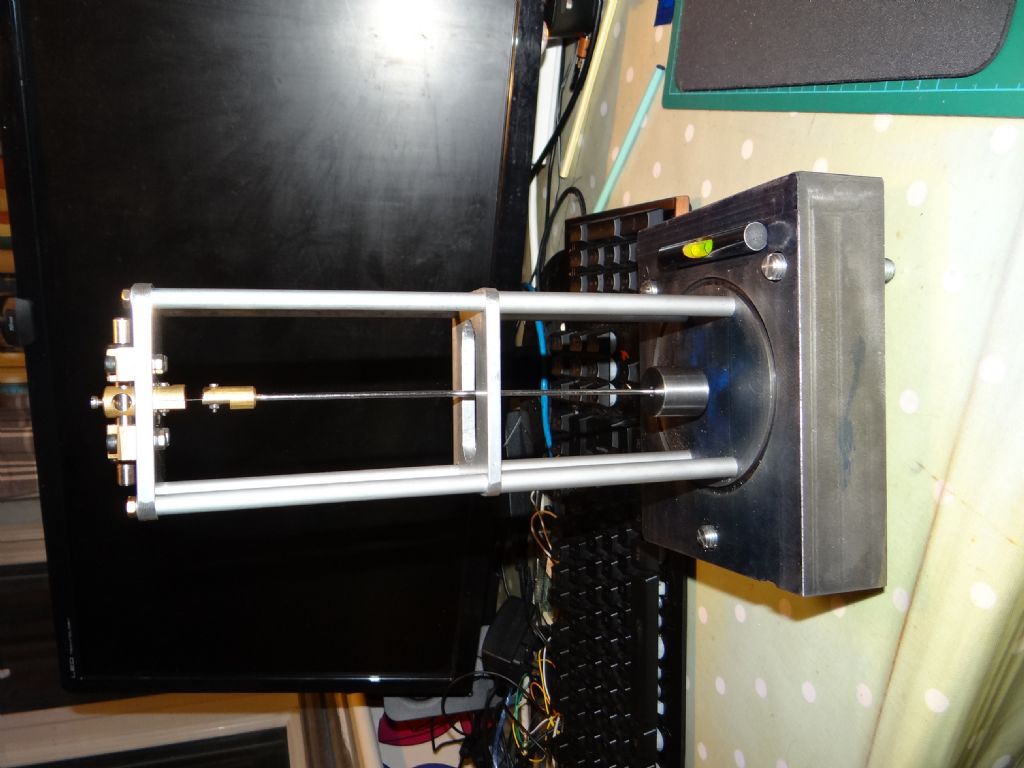
To answer your question, on the top platform the pendulum now hangs from a self-levelling axle – see the Brass work, Silver Steel, and O-ring brakes. Not obvious are considerable improvements in the suspension itself, making sure the spring is held straight, firm, and flexes at a right-angle to the holder in both directions.
The rod is stiffer to reduce whipping, and the bob 5x heavier.
Finally, the heavy cast-iron base is fitted with 3 levelling screws, making it a doddle to level the whole clock. Not shown in the photo, but the screws have locknuts to stop them wobbling against the thread flanks.
Glad you think so John, but I can't honestly claim the credit. I've had enormous help from the forum, on and off-line.
Knowing my limitations, I chose to be open about the design and concepts, inviting comment, criticism and suggestions. The collaboration has been very fruitful. I've enjoyed experimenting, but end result isn't all my own work!
If the prototype proves the concept, I'm sure a competent team could build a better clock on the same principles: more rigidity, improved pendulum, suspension, rod and bob, the electronics are imperfect, the program inefficient, my maths are famously bad, and I doubt my vacuum design will be good enough.
A thought on the front-to-back axis. Bob Matthys points out that this may only hang at an angle where the restoring force is just less than the frictional force, which may be slightly off vertical. Ideally one wants viscous friction to damp it. I believe that Bateman's clock actually has the spring clamped in a ground steel bar that just rests on the bracket so there is no damping at all.
On the measurement front, I can't help thinking that a picPET type device would avoid many of the problems at least for analysing short-term motion of the pendulum in fine detail though the OCXO might not be quite on frequency – but at least you can calibrate that out. TVB says that if you run a picPET to measure GPS pulses you can essentially see the Adev of the OCXO.