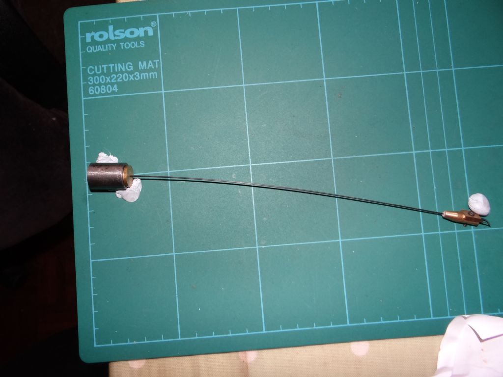
Posted by Michael Gilligan on 20/04/2023 06:19:02:
Posted by duncan webster on 19/04/2023 12:29:21:
It's not clear to me whether the above board includes a focussing lens. I think you'd have to arrange for the pendulum rod to fill the field of view all the time, otherwise it would be sensing the temperature of the background (containment tube when it's fitted, rest of the word when not). It could probably be sorted, but the proxy rod is more straightforward
.
Most unlikely to be able to add a focussing lens … [they are expensive at the relevant wavelengths]
…
I had assumed that filling the field of view with the pendulum bob would be quite simple … although I don’t recall what arc of swing Dave proposes to use.
…
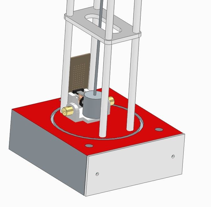
Although using a 4" soil pipe as the vacuum tube creates more space, it's still cramped inside:
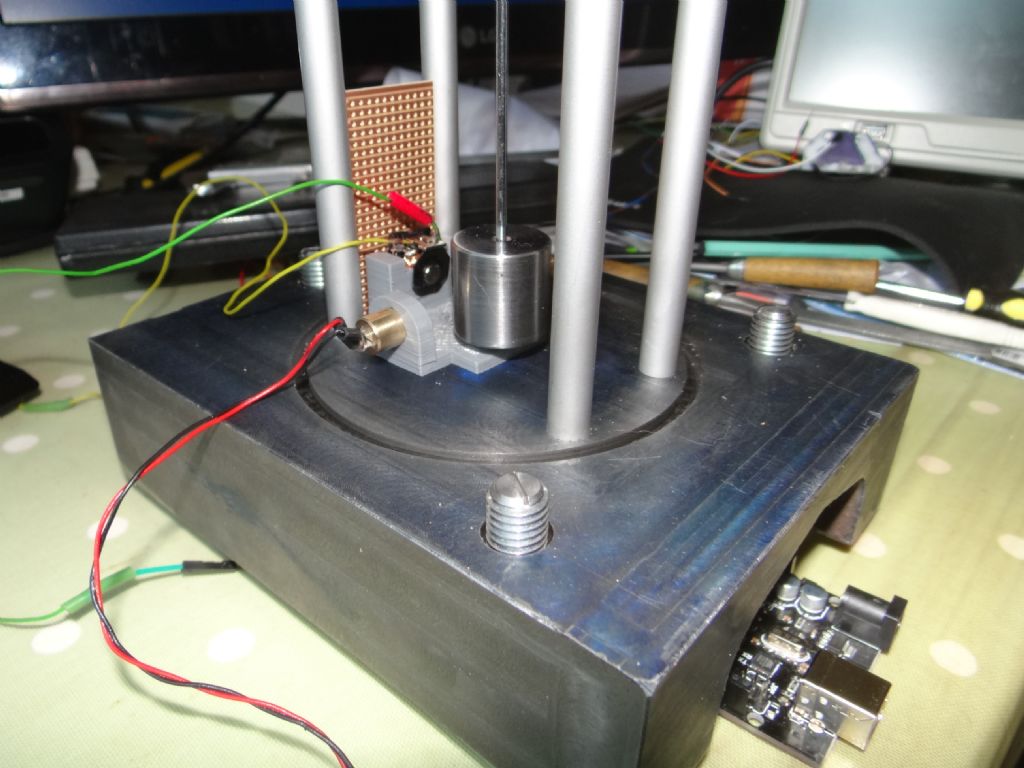
The pendulum is intended to swing up to 5 degrees, so the bob can never be more than 40mm from a sensor. The obvious place to put the IR thermometer module is between the pillars opposite the electromagnet. Could be done, though it means another wire has to penetrate the vacuum seal.
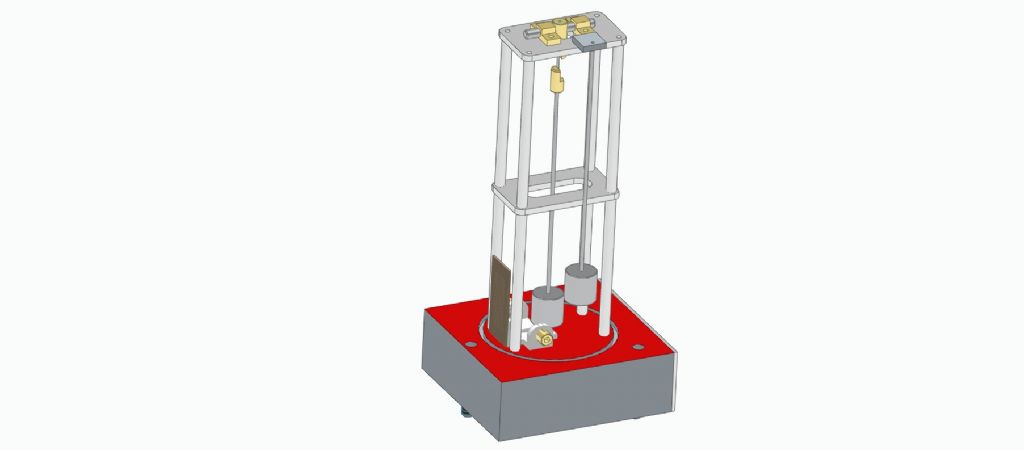
Space for a dummy pendulum looks tight as well, maybe the easy answer is an Invar rod…
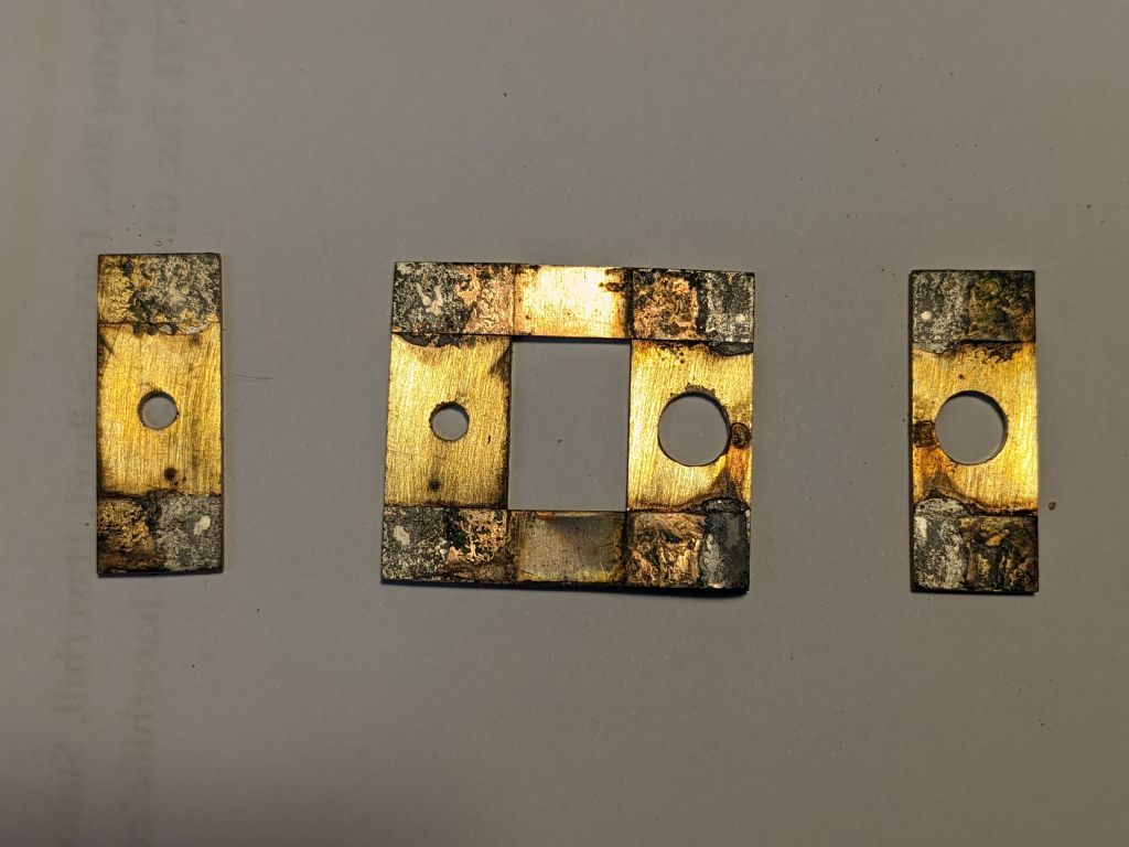
This is why I need to improve my soldering! Having made a new single-spring design which promptly fell apart and needed re-soldering, without much prompting the old one did too! The idea is to get the small gap between the chops completely filled with solder so the length of the spring is completely defined by the edges of the chops. The problem is if you get too much solder between the cheeks it tends to bulge out on to the spring at the edge. In this case the springs have hardly "wetted". So I need to be able to put enough solder paste on to the job when assembling into the soldering jig and also apply resist on the spring to stop it spreading. I have a plan…
I was too cowardly to solder mine so the spring is clamped with M2.5 nuts and bolts. The rod top weighs 9g, the rod 8g, and the bob 95gm, total 112g. As the pendulum will swing about 40,000,000 times a year, I'm hoping clamp pressure is enough to stop the spring from moving!
Posted by Michael Gilligan on 20/04/2023 06:19:02:
Posted by duncan webster on 19/04/2023 12:29:21:
It's not clear to me whether the above board includes a focussing lens. I think you'd have to arrange for the pendulum rod to fill the field of view all the time, otherwise it would be sensing the temperature of the background (containment tube when it's fitted, rest of the word when not). It could probably be sorted, but the proxy rod is more straightforward
.
Most unlikely to be able to add a focussing lens … [they are expensive at the relevant wavelengths]
A quite detailed data-sheet is available via the page that Dave linked,
I had assumed that filling the field of view with the pendulum bob would be quite simple … although I don’t recall what arc of swing Dave proposes to use.
MichaelG.
Edited By Michael Gilligan on 20/04/2023 06:39:18
The bob has a very different area/volume ratio to the rod, so I'd expect it's temperature to lag the rod. Thermal conductivity across metal/metal joints in vacuum is not that good, but gluing the bob to the rod would help. Not sure about heat sink compound, it might evaporate. A drop of high vacuum oil in the joint would do. I'm still backing the proxy rod.
Solder paste is not a good option as it contains too much 'other stuff'. Since all mating surfaces should be jolly flat tin them and while hot wipe off the solder (dampish cotton cloth). Then hold bits in alignment with a jig / clamp and heat the whole lot up making sure the clamp pushes the joint together firmly.
I searched ( tediously) through all the pendulum threads and posts to find what was said about using carbon fibre as the pendulum rod – All I found was related to a carbon fibre in rod form, but not much help beyond that.
Since a single carbon fibre extracted from some high modulus Carbon Tow has a thermal expansion coefficient perhaps 6x less than aluminium, perhaps up to 3x less than steel, and that single fibre will easily support 10kg, is it not practical to use a fibre to support the bob – each end of the fibre fixed say 100mm apart at the top of the pendulum support structure and the bob fitted at the apex of the fibre down below. That would eliminate lateral swing, with a pure arc – along the lines of the dual support spring. I question the 2nd order effects of steel/brass springs – they will resist and assist the swing in their own way. . Perhaps this application of carbon fibre has been covered and rejected for good ( or bad?) reasons, but I could not find any reference.
If you really wanted to compensate the Carbon Fibre thermal performance with ambient temp, simply measuring the temp inside the tube would be sufficient – the fibre is so thin, it would hardly differ in temp from the sensor and surrounding low air pressure ( I assume not a high vacuum..).
Posted by Michael Gilligan on 20/04/2023 06:19:02:
Posted by duncan webster on 19/04/2023 12:29:21:
… It could probably be sorted, but the proxy rod is more straightforward
…
The bob has a very different area/volume ratio to the rod, so I'd expect it's temperature to lag the rod. Thermal conductivity across metal/metal joints in vacuum is not that good, but gluing the bob to the rod would help. Not sure about heat sink compound, it might evaporate. A drop of high vacuum oil in the joint would do. I'm still backing the proxy rod.
How does a vacuum affect the thermal conductivity of a metal to metal joint?
Joy of CAD shows there is room for a dummy pendulum, so both methods are do-able. There's enough space for the fake bob to fit between the swinging real bob and the pipe. Just a simple mock-up:
The bob has a very different area/volume ratio to the rod, so I'd expect it's temperature to lag the rod. Thermal conductivity across metal/metal joints in vacuum is not that good, but gluing the bob to the rod would help. Not sure about heat sink compound, it might evaporate. A drop of high vacuum oil in the joint would do. I'm still backing the proxy rod.
.
Temperature surely needs to stable [not necessarily without some gradient] throughout the pendulum assemblage before any of this becomes useable.
I fear that we are both starting to adopt a ‘Not Invented Here’ posture, Duncan … so I will say no more.
Dave will do as he sees fit, and we will be suitably impressed.
I searched ( tediously) through all the pendulum threads and posts to find what was said about using carbon fibre as the pendulum rod – All I found was related to a carbon fibre in rod form, but not much help beyond that.
… Perhaps this application of carbon fibre has been covered and rejected for good ( or bad?) reasons, but I could not find any reference.
If you really wanted to compensate the Carbon Fibre thermal performance with ambient temp, simply measuring the temp inside the tube would be sufficient – the fibre is so thin, it would hardly differ in temp from the sensor and surrounding low air pressure ( I assume not a high vacuum..).
I blame the forum format because it makes it hard to follow developments, and sometimes there's a long gap between the problem being discussed (haphazardly), and me declaring what I'm doing about it.
Going back a couple of years, my original idea was to use a thin carbon-fibre as a spring – no suspension at all. Not satisfactory because:
Carbon fibre rod is humidity sensitive, because (I think), it affects the springiness of the plastic matrix.
When a conventional spring is inserted, the fibre-rod twangs, which I think explains some of the variation in my pendulum's period.
The fibre is bendy!
So I've switched to steel, assuming that the existing software temperature compensation would cope with it. In true time-nut fashion, that led to the realisation that it's the temperature of the rod that matters, and how to measure it. Plus the rod is well-insulated and will lag behind ambient by some time because it's heated by a circuitous route.
I don't intend to tackle the problem until running the clock in a vacuum shows this to be worth fixing. It's possible the clock and pendulum have so many other faults that this one will be undetectable! An Invar or much thicker fibre rod is also on the cards. It's all experimental!
Dave
I think you need to read my post slowly…
I did not say 'use a carbon fiber rod' – I suggested a single fibre, pure fibre, no plastic matrix involved to absorb moisture( which would nominally not be present in a vacuum anyway) – no twanging possible, much less temp coef than your steel, in fact nominally negative when made hot…
Posted by SillyOldDuffer on 20/04/2023 13:31:32:….
…
I think you need to read my post slowly…
I did not say 'use a carbon fiber rod' – I suggested a single fibre, pure fibre, no plastic matrix involved to absorb moisture( which would nominally not be present in a vacuum anyway) – no twanging possible, much less temp coef than your steel, in fact nominally negative when made hot…
Yikes, I didn't know such a thing existed. Who sells it?
Posted by Michael Gilligan on 20/04/2023 06:19:02:
Posted by duncan webster on 19/04/2023 12:29:21:
… It could probably be sorted, but the proxy rod is more straightforward
…
The bob has a very different area/volume ratio to the rod, so I'd expect it's temperature to lag the rod. Thermal conductivity across metal/metal joints in vacuum is not that good, but gluing the bob to the rod would help. Not sure about heat sink compound, it might evaporate. A drop of high vacuum oil in the joint would do. I'm still backing the proxy rod.
How does a vacuum affect the thermal conductivity of a metal to metal joint?
Joy of CAD shows there is room for a dummy pendulum, so both methods are do-able. There's enough space for the fake bob to fit between the swinging real bob and the pipe. Just a simple mock-up:
Dave
Normally metal to metal joints will have a ‘filler’ of air between the surfaces except at the points where the surfaces are actually in contact ( where the hills of surface roughness coincide). Remove the air film and you loose the conductivity provided by the air film.
Thats my interpretation anyhow.
You really need the rod temperature not the bob which is going to be hard to measure with the IR device. It’s maybe possible with a tiny thermocouple but fiddly and you would probably have to make it coaxial within the rod. The ideal way is the thermal duplicate rod but with a sensor to measure the expansion rather than the temperature but for a first approximation temperature would do.
Posted by Michael Gilligan on 20/04/2023 16:07:06:
Posted by Martin Kyte on 20/04/2023 16:01:50:
.
You really need the rod temperature not the bob
.
I disagree, but presumably [having read my recent post] you know that already.
MichaelG.
Not quite sure which bit you were referring to. However I’m assuming that Dave’s bob is suspended in the middle so cancelling any thermal expansion. The bit you have to worry about is then the expansion of the rod itself. Hence my remark about needing the rod temperature not the bob. You also need the temperature along the length of the rod in order to have a factor that tracks with expansion. That’s also why I suggest measuring the expansion of a dummy rod directly essentially giving you a single number which will track to period.
It does not have the flex springiness of a carbon fibre rod, ie a matrix of fibres in resin. It's mass is nill and I would think would be superior to a 'solid' rod – unless the rod was of significant dimension and mass so that it's inherent resonance is far lower than the pendulum rate.
Since a single carbon fibre extracted from some high modulus Carbon Tow has a thermal expansion coefficient perhaps 6x less than aluminium, perhaps up to 3x less than steel, and that single fibre will easily support 10kg, is it not practical to use a fibre to support the bob – each end of the fibre fixed say 100mm apart at the top of the pendulum support structure and the bob fitted at the apex of the fibre down below. That would eliminate lateral swing, with a pure arc – along the lines of the dual support spring. I question the 2nd order effects of steel/brass springs – they will resist and assist the swing in their own way. . Perhaps this application of carbon fibre has been covered and rejected for good ( or bad?) reasons, but I could not find any reference.
…
Joe's other post was right – I hadn't taken his point properly!
Based on what I found with a single rod, there's a tendency to twist when the bob is impulsed, perhaps because the magnetic field isn't quite aligned with the bob's flight path. Although better engineering might fix this, in a two string swing there's very little to stop oscillation around the Z-axis. Gut feel is strings have more degrees of freedom than a stuff rod and that a flat suspension spring at the top is better at resisting and correcting Z rotation. No numbers backing me up though!
Tradition doesn't help. Most pendulum clocks have rod supported bobs, but maybe that's because they're usually impulsed at the top, and top impulsing a string hung bob wouldn't work. As I'm impulsing the bob at the bottom, maybe a child-swing type pendulum would be OK. Got to be worth trying – more work!
Zero mass? that's an interesting concept. The mass might be low, but a string under tension will still go twang. It could well be that it will have no discernable effect.
However, a very thin string will have little or no stiffness in the plane normal to oscillation, so could it start acting as a Foucault pendulum, is precess due to earth's rotation? 2 strings forming a very shallow vee with the bob at the bottom sounds more sensible then it has resistance to swinging sideways.
You could make impulsing at the top work with a string pendulum if you used something similar to the Reifler method, ie shift the suspension point sideways at the centre of swing (or just before even better)
is it not practical to use a fibre to support the bob – each end of the fibre fixed say 100mm apart at the top of the pendulum support structure and the bob fitted at the apex of the fibre down below. […]
.
Save that they didn’t have the luxury of carbon fibre, this was the system used for some of the earliest serious experiments.
Zero mass? that's an interesting concept. The mass might be low, but a string under tension will still go twang.
It could well be that it will have no discernable effect.
However, a very thin string will have little or no stiffness in the plane normal to oscillation, so could it start acting as a Foucault pendulum, is precess due to earth's rotation?
###### 2 strings forming a very shallow vee with the bob at the bottom sounds more sensible then it has resistance to swinging sideways. ####
I thought that is what I typed…
is it not practical to use a fibre to support the bob – each end of the fibre fixed say 100mm apart at the top of the pendulum support structure and the bob fitted at the apex of the fibre down below. That would eliminate lateral swing.
regarding the twang…The string twangs on a string instrument since it is stretched between two FIXED ( grounded) points.
In the pendulum, one point moves, and the string tension is due to the bob's weight only. If the bob is pulsed in the direction of the swing, there is nothing to twang the string – for practical discussion, that single fibre has NO mass – it is maybe 10-15um diameter. It will also not drag behind the bob position as it is in a vacuum…
I just hung a 4 kg vice from 1.4 m of fabric tape (couldn't find any string) top hooked to my lifting beam. If plucked in the middle it vibrates. Not for very long, too much damping. Agreed it won't twang if you're careful about impulsing, but Michael's post just said it won't twang.
I must read other's posts more carefully re 2 strings! Again you'd need to be careful with impulsing to make sure the bob didn't rock around the string/bob interface