Improved Experimental Pendulum

Advert

Improved Experimental Pendulum

Home Forums Clocks and Scientific Instruments Improved Experimental Pendulum

Viewing 25 posts - 51 through 75 (of 210 total)
  • Author
    Posts
  • #640836
    SillyOldDuffer
    Moderator
      @sillyoldduffer

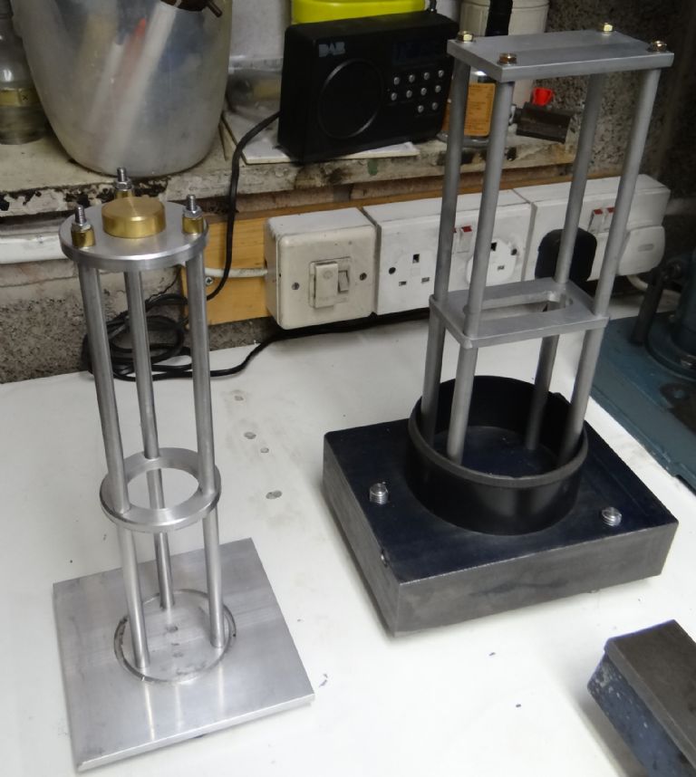
      Still inching along with the rebuild, old and new side by side:

      dsc06735_modified.jpg

      Just testing the gantry goes together and making sure it fits inside the soil pipe. Next job is to finish the top-plate and make the suspension, rod and bob.

      Decided my existing suspension design is too fiddly to make, so have to try for something simpler in CAD before cutting metal.

      Dave

      Advert
      #641712
      SillyOldDuffer
      Moderator
        @sillyoldduffer

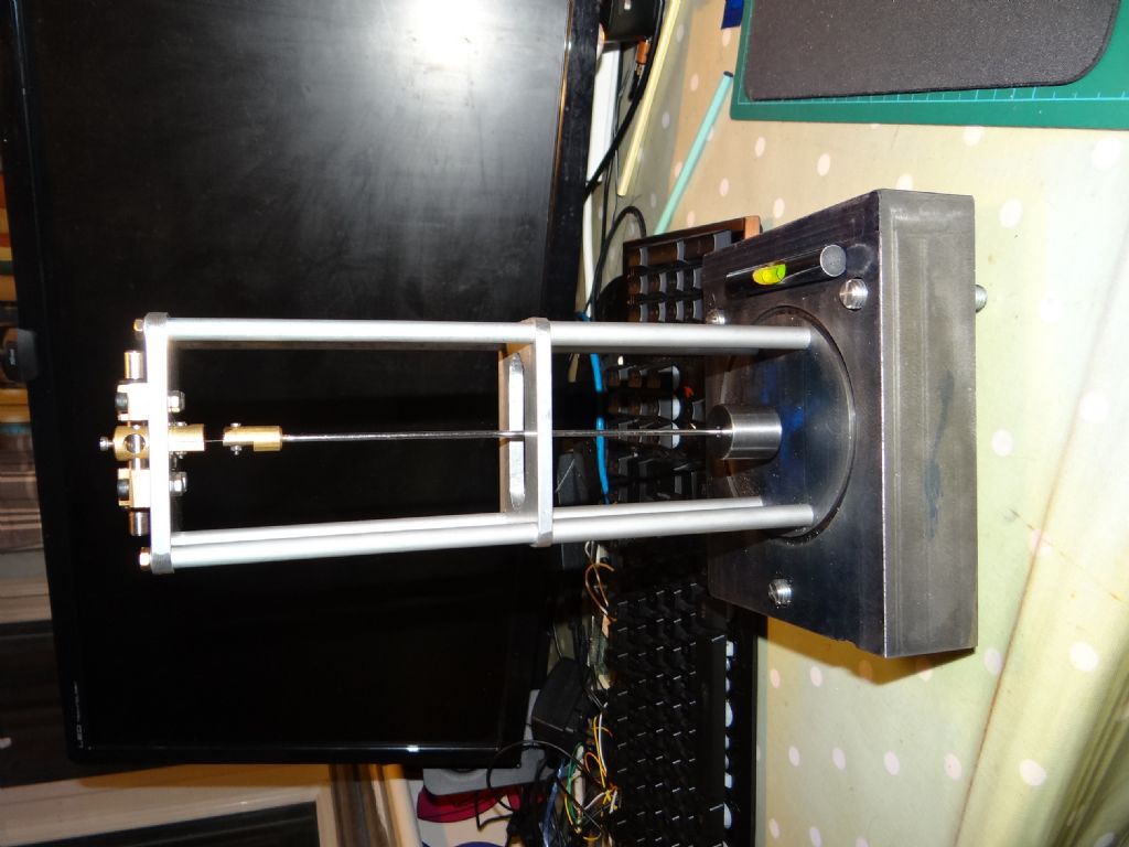
        Getting closer: suspension and bob finished.

        dsc06737.jpg

        The levelling feet work wonderfully, and the bob swings freely with no obvious deviations.

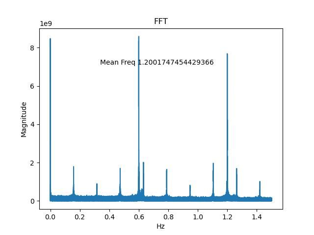
        I abandoned the carbon-fibre pendulum rod after pondering this FFT graph:


        fftlast.jpg

        In theory a pendulum should have no harmonics, and this one does. Pretty sure it's because the carbon-fibre rod (which started as a spring), is twanging. The new rod is 2.7mm steel – much stiffer. It occurred to me that because the clock doesn't use actual period and temperature is compensated in software, the rod changing length significantly as it heats and cools may not matter. We shall see!

        Next step will probably be the beam break and electromagnet assembly. When they're available I can test basic operation of the clock software without mounting the microcontroller, soil pipe, or vacuum pipework. Still haven't decided how to get the electric wiring into the vacuum tube without causing a leak.

        Blood was spilled! The suspension spring is made from a razor blade and I forgot to blunt it…

        Dave

        Edited By SillyOldDuffer on 17/04/2023 21:42:22

        #641714
        John Haine
        Participant
          @johnhaine32865

          What's that FFT of Dave?  Is this impulsed or run-down?

          Edited By John Haine on 17/04/2023 21:52:53

          #641718
          Martin Kyte
          Participant
            @martinkyte99762
            Posted by SillyOldDuffer on 17/04/2023 21:42:10:

            Blood was spilled! The suspension spring is made from a razor blade and I forgot to blunt it…

            Dave

            Edited By SillyOldDuffer on 17/04/2023 21:42:22

            Now you can accurately describe your timepiece as cutting edge technology Dave.

            regards Martin

            #641720
            Bazyle
            Participant
              @bazyle

              As with recent 'bench design' threads and previous lathe bed ones would the support frame benefit from diagonal bracing and perhaps being based on a great big lump of granite?

              #641723
              duncan webster 1
              Participant
                @duncanwebster1

                I would look at mounting your temperature sensor on a dummy pendulum, same diameter and length, mounted outside the containment. This might compensate for the time lag between air temp and rod temp. If the temp sensor is outside the containment this could be quite a long time as vacuum doesn't conduct heat very well.

                #641727
                Joseph Noci 1
                Participant
                  @josephnoci1
                  Posted by duncan webster on 17/04/2023 22:39:27:

                  I would look at mounting your temperature sensor on a dummy pendulum, same diameter and length, mounted outside the containment. This might compensate for the time lag between air temp and rod temp. If the temp sensor is outside the containment this could be quite a long time as vacuum doesn't conduct heat very well.

                  Since Air temp is irrelevant ( no air in the column), surely only the temp of the pendulum rod inside the column is? It's temp is what makes it's length vary, and the lack of air means air density with temp has no meaning.

                  #641743
                  SillyOldDuffer
                  Moderator
                    @sillyoldduffer
                    Posted by Joseph Noci 1 on 18/04/2023 06:43:28:

                    Posted by duncan webster on 17/04/2023 22:39:27:

                    I would look at mounting your temperature sensor on a dummy pendulum, same diameter and length, mounted outside the containment. This might compensate for the time lag between air temp and rod temp. If the temp sensor is outside the containment this could be quite a long time as vacuum doesn't conduct heat very well.

                    Since Air temp is irrelevant ( no air in the column), surely only the temp of the pendulum rod inside the column is? It's temp is what makes it's length vary, and the lack of air means air density with temp has no meaning.

                    Joe confirms my thinking : it's the temperature of the rod that matters.

                    But this is yet more unexplored half-understood territory for me.

                    • At the moment, the design has the sensor mounted on a circuit board inside the vacuum about 20mm distant from the bob. I intend to 3D print the support and plastic is a good insulator. I'm assuming the temperature sensor doesn't need air to work. (There will be some air because it won't be a perfect vacuum, maybe far from it.)
                    • The vacuum container will be a plastic soil-pipe with a plastic cap. Also good insulators.
                    • The whole is mounted on a cast-iron base.

                    I think the main heat-flow would be:

                    • Cast-iron block temperature follows external ambient with a time lag
                    • Inside the vacuum containment, heat travels up the steel-braced Aluminium pillars until it reaches the top-plate.
                    • From top-plate, heat travels via the two Brass trunnions into the levelling axle
                    • From the levelling axle, it travels into the Brass suspension top. (By accident the top is counterbored so the metal to metal contact area is reduced, and I'd expect this to delay heat transfer.
                    • Heat then travels into the suspension spring (a 4mm wide slice of 0.1mm thick stainless steel)
                    • After traversing the spring, heat then enters the brass rod-top, and from there into the 2.7mm diameter Silver Steel rod, about 230mm long.
                    • The rod enters the Mild-steel bob (a 25mm cylinder) through a 4mm diameter hole, and screws into a 6mm diameter brass collar so that the bob is supported at its centre. (So the bob expands and contracts without altering the effective length of the rod.)
                    • Cooling would reverse the heat flow, with the bob providing a reservoir.

                    In short, I expect there to be considerable temperature hysteresis, and it's likely that the sensor and rod won't be at the same temperature. Also, the hysteresis of the rod will be slower than the hysteresis of the sensor.

                    I don't know how much this matters, yet! Possibly it would be better to put the sensor on the top plate rather than close to the base. Or maybe to measure temperature inside near base, inside at top-plate, and outside on base, and see how they correlate. If the hysteresis is predictable based on previous experience, I can compensate for it in software.

                    Anyone know of a way of measuring the temperature of a pendulum rod without disturbing it?

                    Dave

                    #641749
                    Martin Kyte
                    Participant
                      @martinkyte99762
                      Posted by SillyOldDuffer on 18/04/2023 10:07:09:

                      Posted by Joseph Noci 1 on 18/04/2023 06:43:28:

                      Posted by duncan webster on 17/04/2023 22:39:27:

                      I would look at mounting your temperature sensor on a dummy pendulum, same diameter and length, mounted outside the containment. This might compensate for the time lag between air temp and rod temp. If the temp sensor is outside the containment this could be quite a long time as vacuum doesn't conduct heat very well.

                      Since Air temp is irrelevant ( no air in the column), surely only the temp of the pendulum rod inside the column is? It's temp is what makes it's length vary, and the lack of air means air density with temp has no meaning.

                      Joe confirms my thinking : it's the temperature of the rod that matters.

                      But this is yet more unexplored half-understood territory for me.

                      • At the moment, the design has the sensor mounted on a circuit board inside the vacuum about 20mm distant from the bob. I intend to 3D print the support and plastic is a good insulator. I'm assuming the temperature sensor doesn't need air to work. (There will be some air because it won't be a perfect vacuum, maybe far from it.)
                      • The vacuum container will be a plastic soil-pipe with a plastic cap. Also good insulators.
                      • The whole is mounted on a cast-iron base.

                      I think the main heat-flow would be:

                      • Cast-iron block temperature follows external ambient with a time lag
                      • Inside the vacuum containment, heat travels up the steel-braced Aluminium pillars until it reaches the top-plate.
                      • From top-plate, heat travels via the two Brass trunnions into the levelling axle
                      • From the levelling axle, it travels into the Brass suspension top. (By accident the top is counterbored so the metal to metal contact area is reduced, and I'd expect this to delay heat transfer.
                      • Heat then travels into the suspension spring (a 4mm wide slice of 0.1mm thick stainless steel)
                      • After traversing the spring, heat then enters the brass rod-top, and from there into the 2.7mm diameter Silver Steel rod, about 230mm long.
                      • The rod enters the Mild-steel bob (a 25mm cylinder) through a 4mm diameter hole, and screws into a 6mm diameter brass collar so that the bob is supported at its centre. (So the bob expands and contracts without altering the effective length of the rod.)
                      • Cooling would reverse the heat flow, with the bob providing a reservoir.

                      In short, I expect there to be considerable temperature hysteresis, and it's likely that the sensor and rod won't be at the same temperature. Also, the hysteresis of the rod will be slower than the hysteresis of the sensor.

                      I don't know how much this matters, yet! Possibly it would be better to put the sensor on the top plate rather than close to the base. Or maybe to measure temperature inside near base, inside at top-plate, and outside on base, and see how they correlate. If the hysteresis is predictable based on previous experience, I can compensate for it in software.

                      Anyone know of a way of measuring the temperature of a pendulum rod without disturbing it?

                      Dave

                      Duncan is thinking on the right lines in my opinion but the dummy rod needs to be in the chamber with the temperature sensor attached to it. If it is mounted in such a way as to mimic the thermal path of the main pendulum rod then it will track the temperature profile correctly. It obviously needs to be rigidly mounted to avoid any parasitic motion but should be achievable. A real test would be to mount a temporary sensor to the main pendulum and run a test over some days or weeks to see how well the dummy tracks.

                      regards Martin

                      #641750
                      Michael Gilligan
                      Participant
                        @michaelgilligan61133

                        “Anyone know of a way of measuring the temperature of a pendulum rod without disturbing it?”

                        .

                        In principle, an InfraRed thermometer should do it

                        … but it could be a very long journey getting it to work in practice !!

                        MichaelG.

                        #641752
                        duncan webster 1
                        Participant
                          @duncanwebster1

                          Martin has described more eloquently what I was trying to get at, a way of measuring temperature of the pendulum rod without interfering with it's motion, put a non moving dummy in the same environment and measure that.

                          As well as the heat paths listed by SOD there is radiation from the pendulum to the containment tube, but in view of the small temperature differences this should be very small

                          #641754
                          Joseph Noci 1
                          Participant
                            @josephnoci1

                            What about fitting an ESP8266 WiFi uP ( or similar – there are many types) and asmall battery into the pendulum bob position(inside the bob?). Use a thin tube rather than a solid rod for the pendulum and run thin wires up midway with a thermistor at the end. Set the ESP to wake up and do a temp sense every 10min or so and collect that on WiFi. A CR2032 Li cell would last a year or more.

                            If a tube is a no-no, use the rod and superglue 34gauge ins wires neatly along its length to the thermistor.


                            Duncan, My comments were based on your initial statement re the dummy being outside the chamber…like me..

                            Edited By Joseph Noci 1 on 18/04/2023 11:26:54

                            #641759
                            Bazyle
                            Participant
                              @bazyle

                              Would it be simpler to mount the containment tube in its own container which is temperature controlled to a tenth of a degree?

                              #641760
                              John Haine
                              Participant
                                @johnhaine32865

                                Surely if reducing the pressure to eliminate atmospheric effects the best approach is to try to stabilise temperature as well? Of course this could be challenging as there's not much air to distribute the heat.

                                #641765
                                duncan webster 1
                                Participant
                                  @duncanwebster1
                                  Posted by Joseph Noci 1 on 18/04/2023 11:24:58:

                                  What about fitting an ESP8266 WiFi uP ( or similar – there are many types) and asmall battery into the pendulum bob position(inside the bob?). Use a thin tube rather than a solid rod for the pendulum and run thin wires up midway with a thermistor at the end. Set the ESP to wake up and do a temp sense every 10min or so and collect that on WiFi. A CR2032 Li cell would last a year or more.

                                  If a tube is a no-no, use the rod and superglue 34gauge ins wires neatly along its length to the thermistor.

                                  Duncan, My comments were based on your initial statement re the dummy being outside the chamber…like me..

                                  Edited By Joseph Noci 1 on 18/04/2023 11:26:54

                                  Ah, when I said mounted outside, I obviously meant mounted inside. I'm blaming predictive text, or perhaps I was just testing you all. It was late at night as well.

                                  #641767
                                  duncan webster 1
                                  Participant
                                    @duncanwebster1
                                    Posted by Bazyle on 18/04/2023 12:09:45:

                                    Would it be simpler to mount the containment tube in its own container which is temperature controlled to a tenth of a degree?

                                    That has delightful symmetry, SOD is using an OCXO to do the measuring, so making an OCPO (oven controlled pendulum oscillator) has a certain logic.

                                    #641774
                                    duncan webster 1
                                    Participant
                                      @duncanwebster1

                                      Or you could have a double suspension spring like John Haine's, but insulate one half, then you can have a sensor on the pendulum without a battery

                                      #641776
                                      SillyOldDuffer
                                      Moderator
                                        @sillyoldduffer
                                        Posted by Bazyle on 18/04/2023 12:09:45:

                                        Would it be simpler to mount the containment tube in its own container which is temperature controlled to a tenth of a degree?

                                        Might be! This is the world of the time-nut, where not matter how good a clock is, the poor sod building it can always do better.

                                        Back when pendulum clocks were the last word in precision, they were usually bolted to a heavy masonry wall in a locked cellar, deeper the better. Partly to protect them from vibration, but also because temperatures underground don't vary much – natural air-con.

                                        Now I'm thinking of buying a lorry load of two metre diameter concrete sewage pipes and using them to sink a 10 metre deep shaft in my back garden. The clock will live at the bottom…

                                        Dave

                                        #641839
                                        Michael Gilligan
                                        Participant
                                          @michaelgilligan61133

                                          Mildly disappointed [i.e. I will get over it ] that no-one appears to have given any thought to IR thermometers.

                                          When it comes down to it, it’s the actual temperature of the actual pendulum that matters … not some proxy measurement from some surrogate device.

                                          MichaelG.

                                          #641840
                                          Martin Kyte
                                          Participant
                                            @martinkyte99762

                                            Which is why I suggested running a calibration test with a temporary sensor on the actual pendulum to compare with the dummy.

                                            regards Martin

                                            #641849
                                            John Haine
                                            Participant
                                              @johnhaine32865
                                              Posted by duncan webster on 18/04/2023 13:17:09:

                                              Or you could have a double suspension spring like John Haine's, but insulate one half, then you can have a sensor on the pendulum without a battery

                                              I've gone off double springs! See my solder resist thread.

                                              #641886
                                              SillyOldDuffer
                                              Moderator
                                                @sillyoldduffer
                                                Posted by Michael Gilligan on 18/04/2023 21:02:41:

                                                Mildly disappointed [i.e. I will get over it ] that no-one appears to have given any thought to IR thermometers.

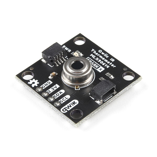
                                                Well I have now, thanks! This module is available from Sparkfun ready to go on an Arduino:

                                                I won't rush to buy one ($32 USD) until it's confirmed that my current temperature arrangement causes detectable errors. (The beast is experimental and may not keep good time for other reasons!)

                                                What could possibly go wrong?

                                                • As far as I know, no-one has ever used one of these in a vacuum to measure the temperature of a moving metal object. The device specs (MLX90614) don't mention any pressure limitations, so the case might pop in a vacuum! (I doubt it). Electrolytic capacitors feel more risky, because big ones come in a thin Aluminium cylinder that's designed to burst if the electrolyte boils. I guess the burst pressure at least 2 bar, but don't know.
                                                • There's already an Infrared transmitter inside the container bouncing IR off the bob. It might interfere with an IR thermometer. Fixable by changing the beam break system to use visible light, so this could become a bigger change than expected.
                                                • I'm still worrying about normally air-cooled electronics overheating in a vacuum. It's another unknown.

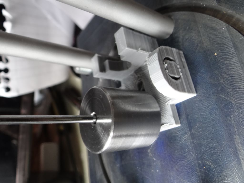
                                                Meanwhile, I 3d-printed the sensor chariot last night. Always a nervous process because STL files are dimensionless and the slicer has to be told what the scale is. Get the scale wrong and the object comes out the wrong size. It's the sort of mistake I'm prone to make, but it fits correctly, phew!

                                                dsc06738.jpg


                                                Next job, remove the sprues, turn the slotted LED holders and fit the electromagnet. Once that's done I can spot glue the chariot in place and confirm the clock still runs. Unlikely, because the bob is much heavier and the electromagnet is near the cast-iron base, which is magnetic. The chariot position and software parameters, mainly impulse power, have to be tuned for acceptable amplitude and reliable running.

                                                In air, the previous pendulum kept best time being lightly impulsed on every beat, basically keeping the amplitude constant. This may not be best for the new pendulum, which is mechanically superior and will be swinging in a vacuum. Therefore I have to retry the huff and puff governed approach, in which the pendulum is allowed to swing free for many beats, and only impulsed when necessary.

                                                Years of work ahead…

                                                Dave


                                                Edited By SillyOldDuffer on 19/04/2023 11:06:10

                                                #641891
                                                duncan webster 1
                                                Participant
                                                  @duncanwebster1

                                                  It's not clear to me whether the above board includes a focussing lens. I think you'd have to arrange for the pendulum rod to fill the field of view all the time, otherwise it would be sensing the temperature of the background (containment tube when it's fitted, rest of the word when not). It could probably be sorted, but the proxy rod is more straightforward

                                                  #641949
                                                  Michael Gilligan
                                                  Participant
                                                    @michaelgilligan61133
                                                    Posted by duncan webster on 19/04/2023 12:29:21:

                                                    It's not clear to me whether the above board includes a focussing lens. I think you'd have to arrange for the pendulum rod to fill the field of view all the time, otherwise it would be sensing the temperature of the background (containment tube when it's fitted, rest of the word when not). It could probably be sorted, but the proxy rod is more straightforward

                                                    .

                                                    Most unlikely to be able to add a focussing lens … [they are expensive at the relevant wavelengths]

                                                    A quite detailed data-sheet is available via the page that Dave linked,

                                                    … but for convenience : **LINK**

                                                    https://cdn.sparkfun.com/assets/8/b/3/2/9/MLX90614_rev001.pdf

                                                    I had assumed that filling the field of view with the pendulum bob would be quite simple … although I don’t recall what arc of swing Dave proposes to use.

                                                    MichaelG.

                                                    Edited By Michael Gilligan on 20/04/2023 06:39:18

                                                    #641953
                                                    John Haine
                                                    Participant
                                                      @johnhaine32865

                                                      Should you be blacking the pendulum bob to get it as near as possible to a "black body"? If it is reflective it will reflect IR from other sources into the temperature sensor as well as what you want.

                                                    Viewing 25 posts - 51 through 75 (of 210 total)
                                                    • Please log in to reply to this topic. Registering is free and easy using the links on the menu at the top of this page.

                                                    Advert

                                                    Latest Replies

                                                    Viewing 25 topics - 1 through 25 (of 25 total)
                                                    Viewing 25 topics - 1 through 25 (of 25 total)

                                                    View full reply list.

                                                    Advert

                                                    Newsletter Sign-up