Improved Experimental Pendulum

Advert

Improved Experimental Pendulum

Home Forums Clocks and Scientific Instruments Improved Experimental Pendulum

Viewing 25 posts - 26 through 50 (of 210 total)
  • Author
    Posts
  • #636521
    John Doe 2
    Participant
      @johndoe2

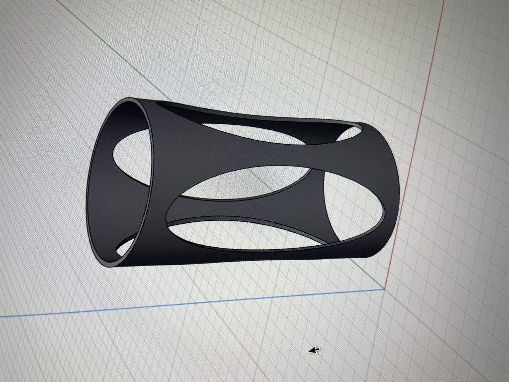
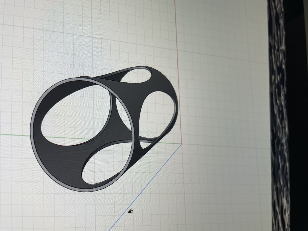
      A subtlety with my suggestion might have been missed. I am not suggesting a closed tube, I am suggesting starting with a closed tube and then milling oval shaped access holes. These holes can be quite big – as long as large webs are left top and bottom, a lot of rigidity will remain while allowing good access to the mechanism.

      Think of the steel roof trusses in your local supermarket or DIY store – commonly have large cut-away diamond or circular holes all along the centre web of the I beam, but retaining (most of) the structural strength, Now imagine that sort of thing rolled into a tube with the access slots around the side wall of the tube, blending into a full tube at the top and bottom, so it would give plenty of access but vastly improved rigidity.

      I would draw what I mean but am busy battling with a broken central heating system – during the coldest part of winter – of course !

      Edited By John Doe 2 on 07/03/2023 11:57:32

      Advert
      #636527
      SillyOldDuffer
      Moderator
        @sillyoldduffer
        Posted by John Doe 2 on 07/03/2023 11:56:29:

        A subtlety with my suggestion might have been missed. I am not suggesting a closed tube, I am suggesting starting with a closed tube and then milling oval shaped access holes. These holes can be quite big – as long as large webs are left top and bottom, a lot of rigidity will remain while allowing good access to the mechanism.

        Think of the steel roof trusses in your local supermarket or DIY store – commonly have large cut-away diamond or circular holes all along the centre web of the I beam, but retaining (most of) the structural strength, Now imagine that sort of thing rolled into a tube with the access slots around the side wall of the tube, blending into a full tube at the top and bottom, so it would give plenty of access but vastly improved rigidity.

        I would draw what I mean but am busy battling with a broken central heating system – during the coldest part of winter – of course !

        No need to draw it John, that's what I understood you to mean. I haven't dismissed the idea, because rigidity is important. The advantage of my tripod is it's easy to make, and provides lots of big gaps. The disadvantage is a tripod can't be as rigid as a tube, or cross-braced structure. Duncan suggested a Shukhov Tower in the other thread:

        These minimise material whilst maximising strength and rigidity. My problem is designing one – it depends on hyperboloid curves, and then assembling it. And it leaves no space for fingers!

        So I have to make compromises, and it's very possible I'll get them wrong. I hope someone else will have a go, because I'm getting more good ideas than I have time to try!

        Though I've not commented on every suggestion made by forum friends, they've all got my attention, and none of them have been rejected entirely. Some are incorporated in the Mk4 clock, and I've no doubt it could be improved, especially if some of my restrictions are ignored, or met by some other clever arrangement!

        Finding time is a problem, especially as I think and do practical stuff slowly, having to fix many silly mistakes as I go. So I'm trying to keep it simple, which is always hard work!

        Dave

        #636541
        John Haine
        Participant
          @johnhaine32865
          Posted by Martin Kyte on 07/03/2023 10:38:15:

          Hi John

          Could you explain a little more about your vacuum filled bellows. I can’t imagine how that works?

          regards Martin

          Think of an aneroid capsule, which is just a bellows with one or maybe 2 folds. Inside there is a vacuum or gas at low pressure. When you pull the ends apart air pressure exerts a force on each one against the pull. If there is actually a vacuum inside the amount of pull doesn't depend on the amount of movement. So except for the bellows material itself there compliance is infinite. Electron microscopes have plenty of vacuum available…

          #636544
          Martin Kyte
          Participant
            @martinkyte99762
            Posted by John Haine on 07/03/2023 14:33:33:

            Posted by Martin Kyte on 07/03/2023 10:38:15:

            Hi John

            Could you explain a little more about your vacuum filled bellows. I can’t imagine how that works?

            regards Martin

            Think of an aneroid capsule, which is just a bellows with one or maybe 2 folds. Inside there is a vacuum or gas at low pressure. When you pull the ends apart air pressure exerts a force on each one against the pull. If there is actually a vacuum inside the amount of pull doesn't depend on the amount of movement. So except for the bellows material itself there compliance is infinite. Electron microscopes have plenty of vacuum available…

            Hi John

            Yes I can see that arrangement would produce a constant force tension spring. It was you saying that the vacuum supported the microscope so I was thinking in terms of compression.
            Thanks Martin

            #636568
            SillyOldDuffer
            Moderator
              @sillyoldduffer

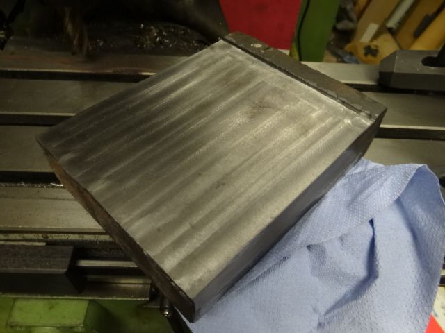
              Been out visiting and to buy food so the block is shaping up slowly. Had to go deeper than expected to get down to clean metal, but it will do.

              dsc06705.jpg

              Could stop here, except I don't often get the chance to square-off a hefty block and need the practice. HSS won't touch the scale and I think the quickest way to shift it is with an angle-grinder.

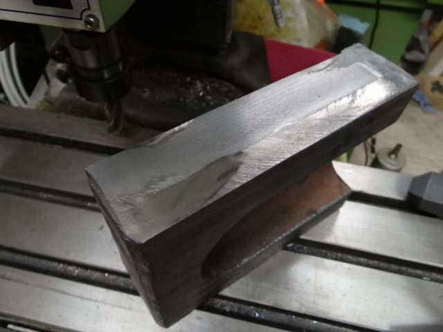
              Decided, again, that I need a bigger milling machine! No chance, unless I buy another house first. As can be seen my biggest end-mill doesn't have the length needed to tidy the edges in one pass:

              dsc06704.jpg

              Tempting to order a carbide shell mill for this but I'll see how my fly-cutter gets on first.

              The job is incredibly dirty, black dust everywhere, and the contents of my nose are extra disgusting. (Bogey photos available if anyone wants evidence!)

              Probably spend this evening exploring frames with Solid Edge.

              Dave

              #636618
              duncan webster 1
              Participant
                @duncanwebster1
                Posted by SillyOldDuffer on 07/03/2023 12:32:59:

                Posted by John Doe 2 on 07/03/2023 11:56:29:

                A subtlety with my suggestion might have been missed. I am not suggesting a closed tube, I am suggesting starting with a closed tube and then milling oval shaped access holes. These holes can be quite big – as long as large webs are left top and bottom, a lot of rigidity will remain while allowing good access to the mechanism.

                Think of the steel roof trusses in your local supermarket or DIY store – commonly have large cut-away diamond or circular holes all along the centre web of the I beam, but retaining (most of) the structural strength, Now imagine that sort of thing rolled into a tube with the access slots around the side wall of the tube, blending into a full tube at the top and bottom, so it would give plenty of access but vastly improved rigidity.

                I would draw what I mean but am busy battling with a broken central heating system – during the coldest part of winter – of course !

                No need to draw it John, that's what I understood you to mean. I haven't dismissed the idea, because rigidity is important. The advantage of my tripod is it's easy to make, and provides lots of big gaps. The disadvantage is a tripod can't be as rigid as a tube, or cross-braced structure. Duncan suggested a Shukhov Tower in the other thread:

                These minimise material whilst maximising strength and rigidity. My problem is designing one – it depends on hyperboloid curves, and then assembling it. And it leaves no space for fingers!

                So I have to make compromises, and it's very possible I'll get them wrong. I hope someone else will have a go, because I'm getting more good ideas than I have time to try!

                Though I've not commented on every suggestion made by forum friends, they've all got my attention, and none of them have been rejected entirely. Some are incorporated in the Mk4 clock, and I've no doubt it could be improved, especially if some of my restrictions are ignored, or met by some other clever arrangement!

                Finding time is a problem, especially as I think and do practical stuff slowly, having to fix many silly mistakes as I go. So I'm trying to keep it simple, which is always hard work!

                Dave

                An unexpected feature of the Shukov tower is that all the diagonal bits are in fact straight, then you just have some simple hoops going circumferential, but it wasn't a serious suggestion. Would be a good talking point tho.

                #636640
                Michael Gilligan
                Participant
                  @michaelgilligan61133

                  Posted by duncan webster on 07/03/2023 23:31:33:

                  .

                  An unexpected feature of the Shukov tower is that all the diagonal bits are in fact straight, then you just have some simple hoops going circumferential, but it wasn't a serious suggestion. Would be a good talking point tho.

                  .

                  So it’s an impressively tall structure comprising a stack of the shapes we discussed before, but with the extra feature that the top hoop of each module is smaller than the bottom.

                  https://en.wikipedia.org/wiki/Hyperboloid#/media/File:Cylinder_-_hyperboloid_-_cone.gif

                  yes MichaelG.

                  .

                  Extending the metaphors … my proposed filament-wound carbon-fibre cone would be similar to the fuselage of the Wellington bomber.

                  https://www.barneswallisfoundation.co.uk/life-and-work/geodetic-aircraft-design/

                  Edited By Michael Gilligan on 08/03/2023 08:39:55

                  #636673
                  John Doe 2
                  Participant
                    @johndoe2

                    This is what I mean – of course the images have come out sideways, and I cannot find how to rotate them but I am sure you get the drift.

                    img_1550.jpeg


                    img_1551.jpeg

                    Moderator Note:  Unfortunately only moderators can rotate photos. It's a forum quirk and turning them is my main service to the community!     Dave

                    Edited By SillyOldDuffer on 08/03/2023 11:37:32

                    #636703
                    SillyOldDuffer
                    Moderator
                      @sillyoldduffer

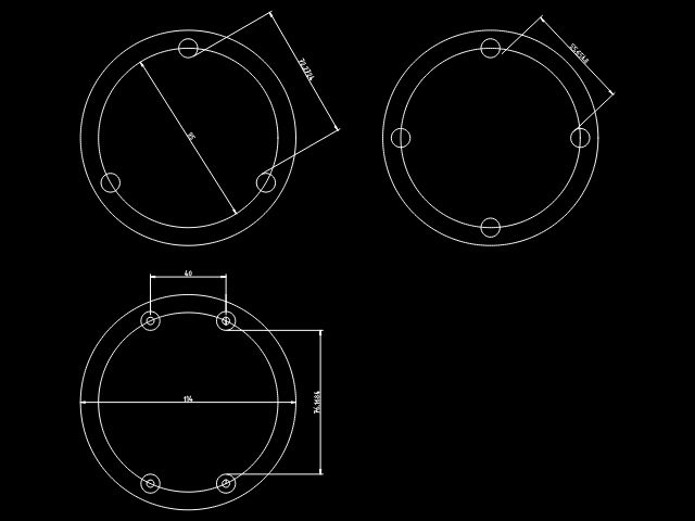
                      Played with some pillar layouts last night with 2D QCAD, which is easier to use for this job than SE:

                      pillars.jpg

                      I measured the space available for my fingers between pillars in three vertical configurations. Equalateral-tripod, square-quadripod, and rectangular-quadripod. Sorry about the blurred numbers – the tripod gives 72.3mm access, square 57.2mm, and the rectangle 70.77mm.

                      My hand: 4-fingers across = 90mm, 4 fingers + thumb = 110mm, and forefinger + thumb = 40mm.

                      The advantage of vertical pillars is space and simplicity of construction. A tilted tripod supporting a 240mm high platform would be angled at about 75°, requiring me to drill diagonally into the base and platform. Could be done, but it's harder to do and more error prone than going straight in with a milling machine. Perhaps in the Mk V!

                      The equilateral triangle both maximise stability, whilst the rectangle gives better access in exchange for less stability sideways (compared to a square.)

                      Spent this morning reading about columns with discouraging results. Apart from the maths boiling my brain, my book says things like "Great and apparently insuperable difficulties arise as soon as we attempt to obtain expressions which relate the strength of longer or more slender columns to their various dimensions."

                      It usefully explains why circular pillars are better than square or other shapes, the importance of fixing the ends, and would help if knowing the safe load was a concern. The safe load doesn't matter because my bob only weighs about 40g and even a spindly tripod will easily support it. And then the chapter on eccentric loads, which covers my case, doesn't cover dynamic loads (a moving pendulum), or say anything about rigidity, which is my chief concern!

                      I hope Solid Edge's Simulation tools will help, but frankly have to admit I barely understand the basics.

                      Going to spend an hour pondering what to do whilst de-scaling cast-iron in the snow. I guess cross-bracing a quadripod is the answer, but I'm not sure how to do it whilst allowing access. Before deciding, I need to model the chariot that carries the sensors and electromagnet. Either it fits through the gap or I have to emplace it first and then erect the scaffold around it. Hmmm.

                      Dave

                      #636730
                      Michael Gilligan
                      Participant
                        @michaelgilligan61133

                        Whatever you decide to do, Dave … please keep us informed

                        This is exciting ‘spectator sport’ devil

                        … and I would be particularly interested if you can share what Solid Edge can tell about vibration modes.

                        MichaelG.

                        #640151
                        SillyOldDuffer
                        Moderator
                          @sillyoldduffer

                          Slow progress for various reasons, but I'm getting there.

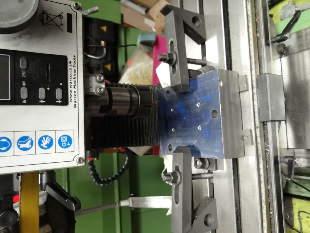
                          This is the base squared off and tapped to take the support columns:

                          dsc06727.jpg

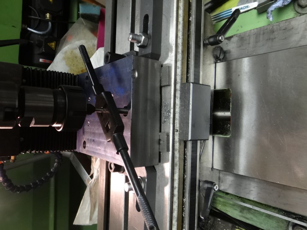
                          And here I'm tapping the holes for the M12 adjustable feet:

                          dsc06728.jpg

                          Annoyingly the Aluminium tube needed to complete the four pillars has gone walk-about and I've decided to buy more.

                          The only remaining major operation on the base is cutting the 4mm wide circular slot needed to take a 4" diameter plastic soil pipe. Not sure whether to trepan the slot in the lathe or mill it. The problem is how to hold a block of that size. May open another thread on the subject – it's work-holding and cutting rather than clock related.

                          I'm dithering about where to put the vacuum outlet too. Under the block's centre of gravity for balance, but that puts it directly under pendulum BDC, where running the pump seems most likely to disturb the bob. Dithering about the rod as well, having gone off thin carbon-fibre, so probably another question coming in the Precision Pendulum thread.

                          Applying "lessons learnt" is proving painful!

                          Dave


                          Edited By SillyOldDuffer on 04/04/2023 12:31:39

                          #640382
                          SillyOldDuffer
                          Moderator
                            @sillyoldduffer

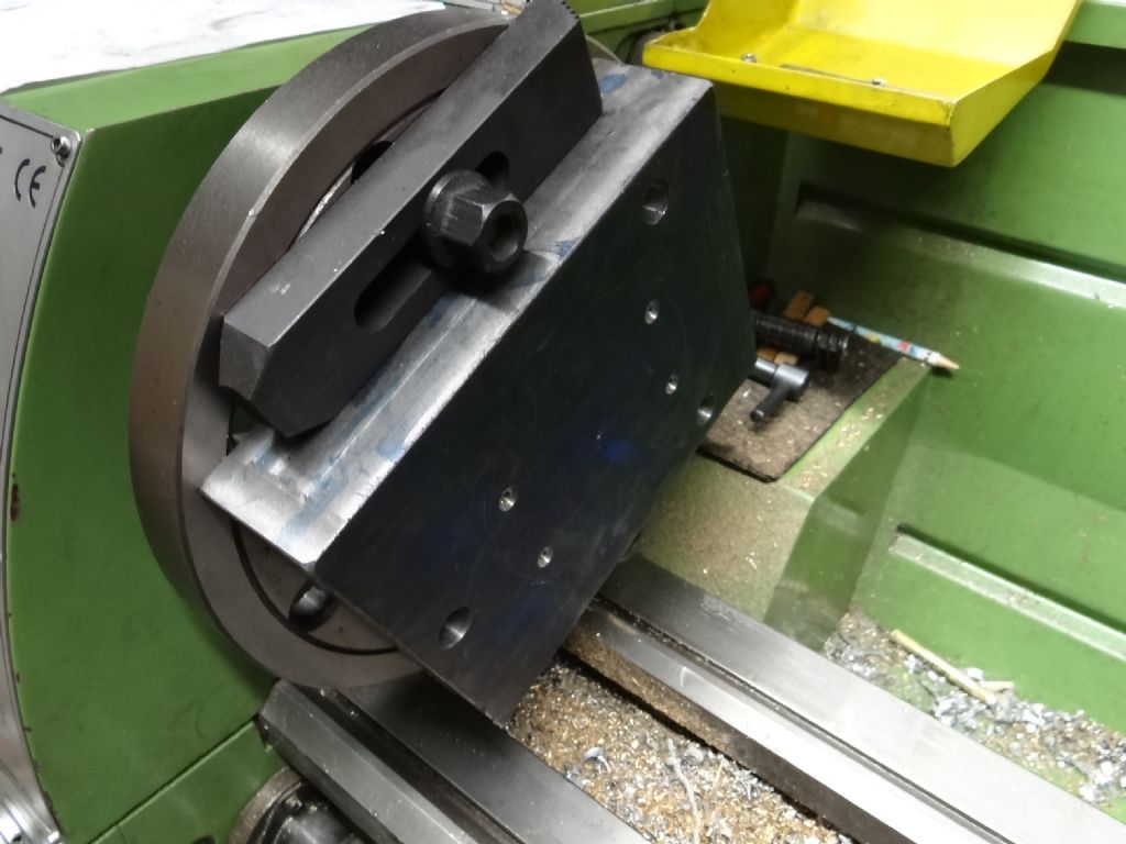
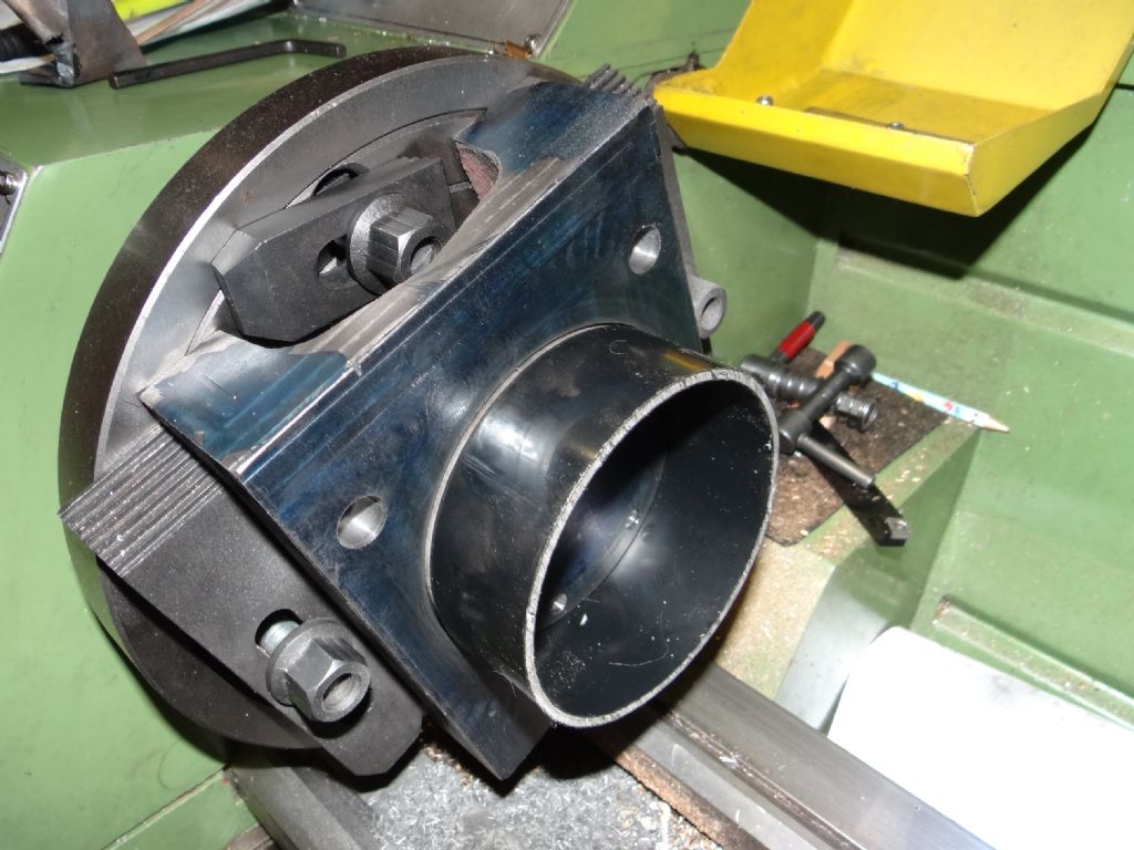
                            Decided the base block was too big for my rotary table without making some sort of platform, so I'm going to trepan it. The block clamps nicely to my 240mm diameter faceplate using its levelling screws:

                            dsc06729.jpg

                            The milling table clamp on top is for balance, not holding. There are 3 of them, and I'll find out how effective they are when the faceplate is powered up. Only about 100rpm, but it will be shake, rattle and roll if the balance is off.

                            Now all I have to do is grind a trepanning tool, and I'm infamously cack-handed. What could possibly go wrong? Fingers crossed!

                            Dave

                            #640420
                            SillyOldDuffer
                            Moderator
                              @sillyoldduffer

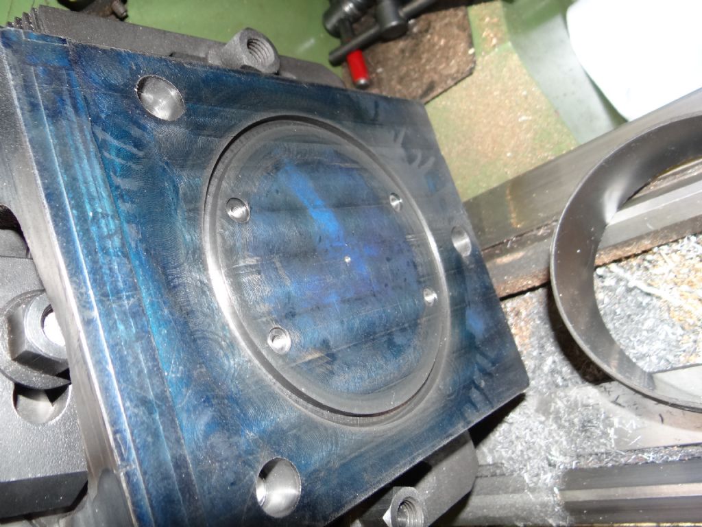
                              Worked out OK :

                              dsc06731.jpg

                              And the test section of pipe fits perfectly, phew:

                              dsc06730.jpg

                              Dave

                              Edited By SillyOldDuffer on 06/04/2023 19:48:27

                              #640422
                              Michael Gilligan
                              Participant
                                @michaelgilligan61133

                                Great progress, Dave yes

                                Presumably you will eventually be bedding the tube onto Silicone sealant or some-such

                                MichaelG.

                                #640493
                                SillyOldDuffer
                                Moderator
                                  @sillyoldduffer
                                  Posted by Michael Gilligan on 06/04/2023 19:58:10:

                                  Great progress, Dave yes

                                  Presumably you will eventually be bedding the tube onto Silicone sealant or some-such

                                  MichaelG.

                                  Yes, that's how the Mark I was attempted. Didn't work well, slow leak, but seal finish was poor and there were 4 unhelpful through holes as well. (for the pillars) This time, I'm going to try an O-ring first. However, the construction depends too much on the weight of the pipe and air-pressure to squish the ring for my liking – it isn't a proper compression fitting. So silicon goo is the odds-on favourite.

                                  Not too worried about the other end of the soil pipe. It came with a flange incorporating a neoprene seal – wrong way round – but I can glue the tight fitting top cap in as well.

                                  The vacuum design has me uneasy for other reasons. Positioning the vent already mentioned, but also how to keep it and the electrical wiring air-tight. Ideally, the pump should take the pressure down once and thereafter the container never leaks. Fat chance! Other concerns: where to put the vacuum gauge; pipe size; will an ordinary water isolation valve be good enough; and making sure running the vacuum pump doesn't shake the whole shebang.

                                  Slow progress – I'm wasting loads of time on domestics.

                                  Dave

                                  #640497
                                  Martin Kyte
                                  Participant
                                    @martinkyte99762

                                    Hi Dave

                                    A matrix of pins embedded in araldite in a flange of your choice makes for a good vacuum feedthrough although there are plenty of commercial versions available.

                                    regards Martin

                                    #640502
                                    Neil Wyatt
                                    Moderator
                                      @neilwyatt
                                      Posted by Martin Kyte on 07/03/2023 10:38:15:

                                      Hi John

                                      Could you explain a little more about your vacuum filled bellows. I can’t imagine how that works?

                                      regards Martin

                                      I was tempted to say he took all the air out, then carefully let some vacuum in

                                      Neil

                                      #640520
                                      duncan webster 1
                                      Participant
                                        @duncanwebster1
                                        Posted by Martin Kyte on 07/04/2023 15:52:38:

                                        Hi Dave

                                        A matrix of pins embedded in araldite in a flange of your choice makes for a good vacuum feedthrough although there are plenty of commercial versions available.

                                        regards Martin

                                        When I worked on gas centrifuges, which run at far higher vacuum than a clock, we used Oxley pins to get power in. Oxley Developments, Ulverston. They might send you a few as a sample if you ask them nicely. Otherwise, a ptfe disc with interference fit pins would be a close replica.

                                        #640549
                                        John Haine
                                        Participant
                                          @johnhaine32865

                                          Maybe you could avoid pins altogether? Use a "wireless power" setup (chips and coils readily available) to transfer power through the plastic pipe, put the processor inside the enclosure, Bluetooth or Wi-Fi to get the data out?

                                          #640566
                                          SillyOldDuffer
                                          Moderator
                                            @sillyoldduffer
                                            Posted by John Haine on 08/04/2023 10:14:46:

                                            Maybe you could avoid pins altogether? Use a "wireless power" setup (chips and coils readily available) to transfer power through the plastic pipe, put the processor inside the enclosure, Bluetooth or Wi-Fi to get the data out?

                                            That's a good idea. A variant would be to run a single power feed through the base and use the base itself as ground. Easier to seal one connection than four, more when a display is added.

                                            But would running normally air-cooled electronics in a vacuum cause them to overheat?

                                            Dave

                                            #640567
                                            Joseph Noci 1
                                            Participant
                                              @josephnoci1
                                              Posted by SillyOldDuffer on 08/04/2023 12:50:36:

                                              But would running normally air-cooled electronics in a vacuum cause them to overheat?

                                              Dave

                                              And then stretch your pendulum that your are trying to insulate from the environment..

                                              #640568
                                              duncan webster 1
                                              Participant
                                                @duncanwebster1

                                                As little as possible inside, then you can play around with it without breaching vacuum

                                                #640573
                                                Michael Gilligan
                                                Participant
                                                  @michaelgilligan61133
                                                  Posted by duncan webster on 08/04/2023 13:20:04:

                                                  As little as possible inside, then you can play around with it without breaching vacuum

                                                  .

                                                  +1 for that

                                                  MichaelG.

                                                  #640641
                                                  SillyOldDuffer
                                                  Moderator
                                                    @sillyoldduffer
                                                    Posted by Michael Gilligan on 08/04/2023 13:52:30:

                                                    Posted by duncan webster on 08/04/2023 13:20:04:

                                                    As little as possible inside, then you can play around with it without breaching vacuum

                                                    .

                                                    +1 for that

                                                    MichaelG.

                                                    I can consider encapsulating because my rather complicated clock & logging electronics are already designed for remote operation, running over WiFi. Done so I can modify the software without going near the physical clock, but it could all be installed inside the pipe.

                                                    Mechanical adjustments are the main reason for opening the case, and they shouldn't be necessary once the beam break sensor is positioned. Not much reason to open up once the pendulum is swinging because rate, temperature and pressure are all compensated in software.

                                                    The main problem with the suggestion, I think, is keeping the electronics cool inside a vacuum. A vacuum is an excellent insulator and there's no point spinning a fan in one!

                                                    On balance, I feel it's easier to make an air-tight connector for 3 or four wires. Araldite should do it!

                                                    Dave

                                                    #640663
                                                    duncan webster 1
                                                    Participant
                                                      @duncanwebster1

                                                      With a Fedchenko type drive you could mount everything outside the vacuum containment with a non magnetic diaphragm to isolate the pendulum. A second hall effect sensor would monitor amplitude.

                                                      You could even do this with a tee shaped pendulum, have the end of the tee running in a tunnel with the drive coil external.

                                                    Viewing 25 posts - 26 through 50 (of 210 total)
                                                    • Please log in to reply to this topic. Registering is free and easy using the links on the menu at the top of this page.

                                                    Advert

                                                    Latest Replies

                                                    Viewing 25 topics - 1 through 25 (of 25 total)
                                                    Viewing 25 topics - 1 through 25 (of 25 total)

                                                    View full reply list.

                                                    Advert

                                                    Newsletter Sign-up