I have a computer, I need a simple oscilloscope

Advert

I have a computer, I need a simple oscilloscope

Home Forums Electronics in the Workshop I have a computer, I need a simple oscilloscope

Viewing 11 posts - 26 through 36 (of 36 total)
  • Author
    Posts
  • #614853
    Robert Atkinson 2
    Participant
      @robertatkinson2

      Maurice,

      Any of the current picoscope will do the job. The lowest perfomance model is DC to 5MHz bandwidth, two channel and has a built in signal generator as a bonus, The one I have to lend is a 2203 with that specification. New they are around £100 (currently the lowest spec model for sale is the 2204 10MHz version due to the chip shortage. It's £115 including two probes. Beware ebay "resellers" who are charging up to 3 times this!
      I've been using Pico Technology products for over 20 years both personally and professionally and have never had any issue with the product or their support.

      Robert G8RPI.

      Advert
      #614878
      SillyOldDuffer
      Moderator
        @sillyoldduffer
        Posted by DC31k on 24/09/2022 18:09:39:

        Posted by SillyOldDuffer on 24/09/2022 17:46:55:

        Operation: set the wiper to ground…

        And that is the flaw in the plan. It relies on the knob-twiddler performing his duty with 100% reliability every single time without fail after every change to the input conditions.

        If you could show something with a kind of dead-man's control on it that absolutely cannot put anything into the sound card input without positive human action, that would be the beginning of a way forward.

        If you can incorporate something in it that will prevent overvoltage altogether (perhaps caused by an involuntary jerk due to sneezing when adjusting the pot), that would increase the reliability of the system.

        I'm all in favour of risk managed approaches, and thought for Tim's investigations a pot would be sufficient. However, as this was a good excuse to get out of urgent house-work, I tried the experiment.

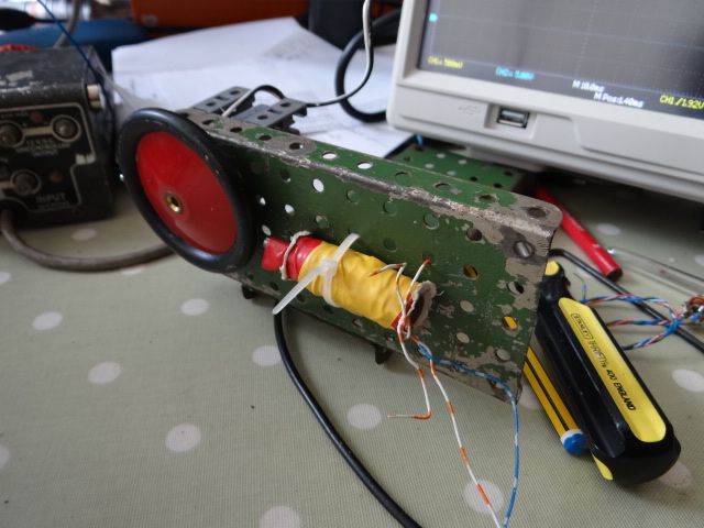
        Apparatus: A meccano lash-up with motor and wheel that spins a small super-magnet past a sawn-off nail with a few hundred turns of magnet wire coiled around it. The magnet is the shiny dot on the opposite side of the wheel to the nail and coil:

        dsc06643.jpg

        A Siglent SDS1102 CML oscilloscope

        Method:

        Oscilloscope was connected to the coil on the 5V / graduation range and the wheel turned slowly by hand. This showed a pulse of about ±0.15V so the oscilloscope' sensitivity was increased to 200mV per graduation and the motor powered up with a 1.2V AA cell.

        Results.

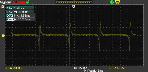
        magmeasure1.jpg

        The oscilloscope registers almost exactly 10Hz so the motor is revolving at 600rpm

        The voltage spike is larger than I expected, at 760mV roughly double the turned by hand voltage

        Conclusion

        I knew but forgot that the voltage generated when a magnet passes a coil is proportional to the speed of transit. Thus, connecting this circuit directly to a sound-card is riskier than I expected! At 600rpm my experimental set-up wouldn't damage a sound-card, but higher rpm exceeds the limit. (At 4000rpm the set-up produces 2.75V pulses.)

        My pot circuit is too simple to protect the sound-card if the rpm varies.

        ————-

        I think Tim is looking for a display like this:

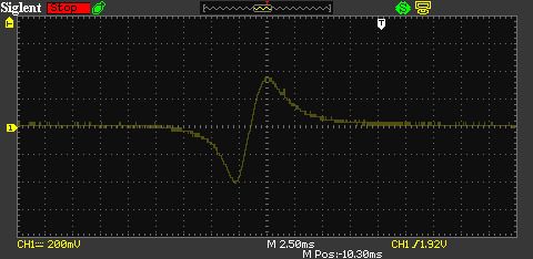
        magmeasure2.jpg

        The voltage swings ever more negative as the magnet approaches the coil, then flips to positive as the magnet passes TDC, and and falls as the magnet moves out of range. (Reversing the magnet would cause the pulse to go positive then negative.) Anyway, if I've remembered correctly, the voltage is proportional to the rate of change when the coil flips from negative to positive, which depends on how fast the magnet is moving – RPM.

        Dave

        #614900
        duncan webster 1
        Participant
          @duncanwebster1

          Using a hall effect probe would make voltage in dependant of speed, and unidirectional.

          If the OP's computer has a bidirectional parallel port I can provide an old pico scope unit, no use to me, but too good to chuck

          #614912
          DC31k
          Participant
            @dc31k
            Posted by SillyOldDuffer on 25/09/2022 12:14:58:

            The voltage swings ever more negative as the magnet approaches the coil, then flips to positive as the magnet passes TDC

            Thankyou for your efforts. It is interesting stuff.

            On the trace, where exactly is TDC? Is it at the point of maximum negative voltage, at the zero crossing point or at the maximum positive voltage?

            How many degrees of rotation does it represent from peak to peak? How many degrees from leaving the zero line to crossing it from below to meeting it again from above? The curve looks slightly asymmetric. Any speculation why?

            Thanks again.

            #614916
            Robert Atkinson 2
            Participant
              @robertatkinson2
              Posted by SillyOldDuffer on 25/09/2022 12:14:58:

              Posted by DC31k on 24/09/2022 18:09:39:

              Posted by SillyOldDuffer on 24/09/2022 17:46:55:

              Operation: set the wiper to ground…

              And that is the flaw in the plan. It relies on the knob-twiddler performing his duty with 100% reliability every single time without fail after every change to the input conditions.

              If you could show something with a kind of dead-man's control on it that absolutely cannot put anything into the sound card input without positive human action, that would be the beginning of a way forward.

              If you can incorporate something in it that will prevent overvoltage altogether (perhaps caused by an involuntary jerk due to sneezing when adjusting the pot), that would increase the reliability of the system.

              I'm all in favour of risk managed approaches, and thought for Tim's investigations a pot would be sufficient. However, as this was a good excuse to get out of urgent house-work, I tried the experiment.

              Apparatus: A meccano lash-up with motor and wheel that spins a small super-magnet past a sawn-off nail with a few hundred turns of magnet wire coiled around it. The magnet is the shiny dot on the opposite side of the wheel to the nail and coil:

              dsc06643.jpg

              A Siglent SDS1102 CML oscilloscope

              Method:

              Oscilloscope was connected to the coil on the 5V / graduation range and the wheel turned slowly by hand. This showed a pulse of about ±0.15V so the oscilloscope' sensitivity was increased to 200mV per graduation and the motor powered up with a 1.2V AA cell.

              Results.

              magmeasure1.jpg

              The oscilloscope registers almost exactly 10Hz so the motor is revolving at 600rpm

              The voltage spike is larger than I expected, at 760mV roughly double the turned by hand voltage

              Conclusion

              I knew but forgot that the voltage generated when a magnet passes a coil is proportional to the speed of transit. Thus, connecting this circuit directly to a sound-card is riskier than I expected! At 600rpm my experimental set-up wouldn't damage a sound-card, but higher rpm exceeds the limit. (At 4000rpm the set-up produces 2.75V pulses.)

              My pot circuit is too simple to protect the sound-card if the rpm varies.

              ————-

              I think Tim is looking for a display like this:

              magmeasure2.jpg

              The voltage swings ever more negative as the magnet approaches the coil, then flips to positive as the magnet passes TDC, and and falls as the magnet moves out of range. (Reversing the magnet would cause the pulse to go positive then negative.) Anyway, if I've remembered correctly, the voltage is proportional to the rate of change when the coil flips from negative to positive, which depends on how fast the magnet is moving – RPM.

              Dave

              It would be interesting to see what your test setup produces with a soundcard 'scop software you proposed. Have to tried it?

              #614930
              Tim Stevens
              Participant
                @timstevens64731

                Hello again
                Dave (s-o-d) has got it about right.
                The engine needs a spark at a progessively earlier time before TDC as the speed rises. In the past this was done by a centrifugally advancing cam in the contact breaker.
                The ignition device needs to be set to 'open the theoretical points' when the output from the trigger coil gets to a set voltage. As the rotation speeds up, the whole wave increases in size, and therefore reaches a given voltage earlier. The system does not rely on a slotted disc, or a Hall sensor – they were a later development in vehicle use.

                What I hope to do is to be able to tweak the shape and size of the voltage curve so that the advance produced can be matched (by road testing) to a given engine and given settings. The system I have already made as a first try does seem to work fairly well, and this is a fortunate accident rather than cleverness. What I seek the to change, for example, the radius of the rotor, the distance to the magnet, the strength of the magnet, the shape of any pole piece on the magnet, etc, to vary the advance curve in known ways at low, or high, revs, so the the original set-up can be improved. Or by changing things, to show that the original guess was jolly nearly right anyway and best left as it is.

                Hope this helps

                Cheers, Tim

                #614938
                Maurice Taylor
                Participant
                  @mauricetaylor82093
                  Posted by Robert Atkinson 2 on 25/09/2022 10:25:35:

                  Maurice,

                  Any of the current picoscope will do the job. The lowest perfomance model is DC to 5MHz bandwidth, two channel and has a built in signal generator as a bonus, The one I have to lend is a 2203 with that specification. New they are around £100 (currently the lowest spec model for sale is the 2204 10MHz version due to the chip shortage. It's £115 including two probes. Beware ebay "resellers" who are charging up to 3 times this!
                  I've been using Pico Technology products for over 20 years both personally and professionally and have never had any issue with the product or their support.

                  Robert G8RPI.

                  Hi, Thank you for your reply

                  Maurice

                  #614958
                  duncan webster 1
                  Participant
                    @duncanwebster1

                    If you use a processor you could have the trigger way early, then create the spark after a time delay dependant on rpm and inlet vacuum. I seem to remember old fashioned distributors had a connection to the inlet manifold. You can also have any relationship between the various parameters just by altering the code.

                    #615019
                    Robert Atkinson 2
                    Participant
                      @robertatkinson2

                      One thing to consider is the location of the magnet. The "obvious" and common place to put it is on the rotating part. This can however make shaping the pole pieces to adjust the waveform difficult. Another location that works is to put the magnet on the end of the core the coil is wound on furthest from the rotating part. This assumes of course that the rotating part is made from magnetic material. This allows more freedom in shaping both fixed and moving pole pieces.

                      Robert.

                      #615028
                      SillyOldDuffer
                      Moderator
                        @sillyoldduffer
                        Posted by Robert Atkinson 2 on 25/09/2022 16:28:38:

                        Posted by SillyOldDuffer on 25/09/2022 12:14:58:

                        Posted by DC31k on 24/09/2022 18:09:39:

                        Posted by SillyOldDuffer on 24/09/2022 17:46:55:

                        …:

                        Results.

                        magmeasure1.jpg

                        The oscilloscope registers almost exactly 10Hz so the motor is revolving at 600rpm

                        ….

                        Dave

                        It would be interesting to see what your test setup produces with a soundcard 'scop software you proposed. Have to tried it?

                        I have now, downloaded from here:

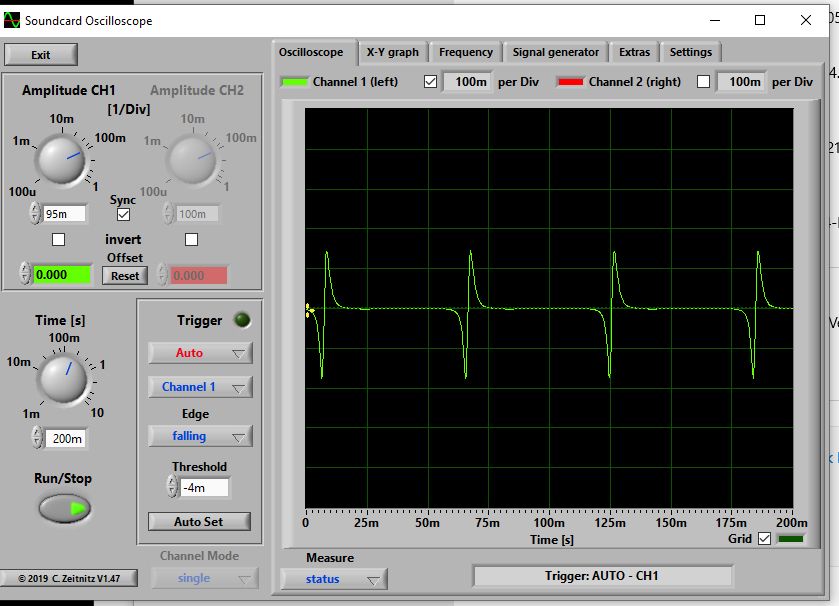
                        soundcard.jpg

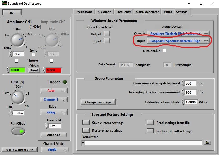
                        Slightly fussy getting it to recognise the input. My windows 10 PC has a Line-In (coded pink) socket on the front panel. Plugging in woke up the Realtek Audio mixer and I had to select Line-In. The scope still didn't work until I opened its settings tab (far right) and changed the input from Lookback to Line-In.

                        soundcardio.jpg

                        As I was certain my lash up powered by a 1.2V battery wouldn't over-volt the computer input, I connected directly. Might try a pair of back to back diodes later.

                        The waveform is in close agreement with the Siglent so concerns about soundcards only having an AC input are put to rest in this case.

                        Won't have a chance to think about Robert's questions until later this afternoon, but they're interesting too.

                        Dave

                        #615083
                        Robert Atkinson 2
                        Participant
                          @robertatkinson2

                          Thanks for that Dave,
                          Looks like good waveform fidelity. Amplitude is quite a bit off though. I wonder if the software has a calibration routine? One advantage of this application is the input signal is isolated so no ground loops.

                          Robert.

                        Viewing 11 posts - 26 through 36 (of 36 total)
                        • Please log in to reply to this topic. Registering is free and easy using the links on the menu at the top of this page.

                        Advert

                        Latest Replies

                        Viewing 25 topics - 1 through 25 (of 25 total)
                        Viewing 25 topics - 1 through 25 (of 25 total)

                        View full reply list.

                        Advert

                        Newsletter Sign-up