Hudswell Clarke D604

Advert

Hudswell Clarke D604

Home Forums Locomotives Hudswell Clarke D604

Viewing 3 posts - 1 through 3 (of 3 total)
  • Author
    Posts
  • #77216
    Sub Mandrel
    Participant
      @submandrel
      Answers to my first set of queries convinced me a 3 1/2″ gauge model of this sad old diesel shunter was a working proposition.
       
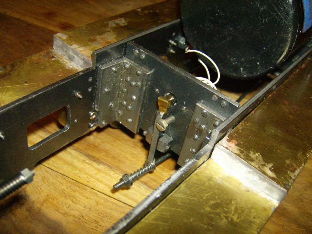
      I have made a basic start on the frames and drag beams:
       

      I won’t show you the rivets from the back!
       
      I’ve cadged alot of hints about 3 1/2″ gauge dimensions from the Roedean series, knowing my daughter’s height at around the time of the photos I have has helped me with scaling from them! Luckily two photos off the web were much better and revealed important detail – like rivits on the front drag beam, but not on the back!
       
      Can anyone give advice on the correct size and material for making the draw hook and three-link chain? It seems these shunters had plain chain.
       
      Another question are 7 1/16″ rivets strong enough for fixing those angles? Should I ad a couple of bigger countersunk screws or rivets?
       
      Thanks for ideas and encouragement!
       
      Neil

      Advert
      #1045
      Sub Mandrel
      Participant
        @submandrel
        #87600
        Sub Mandrel
        Participant
          @submandrel

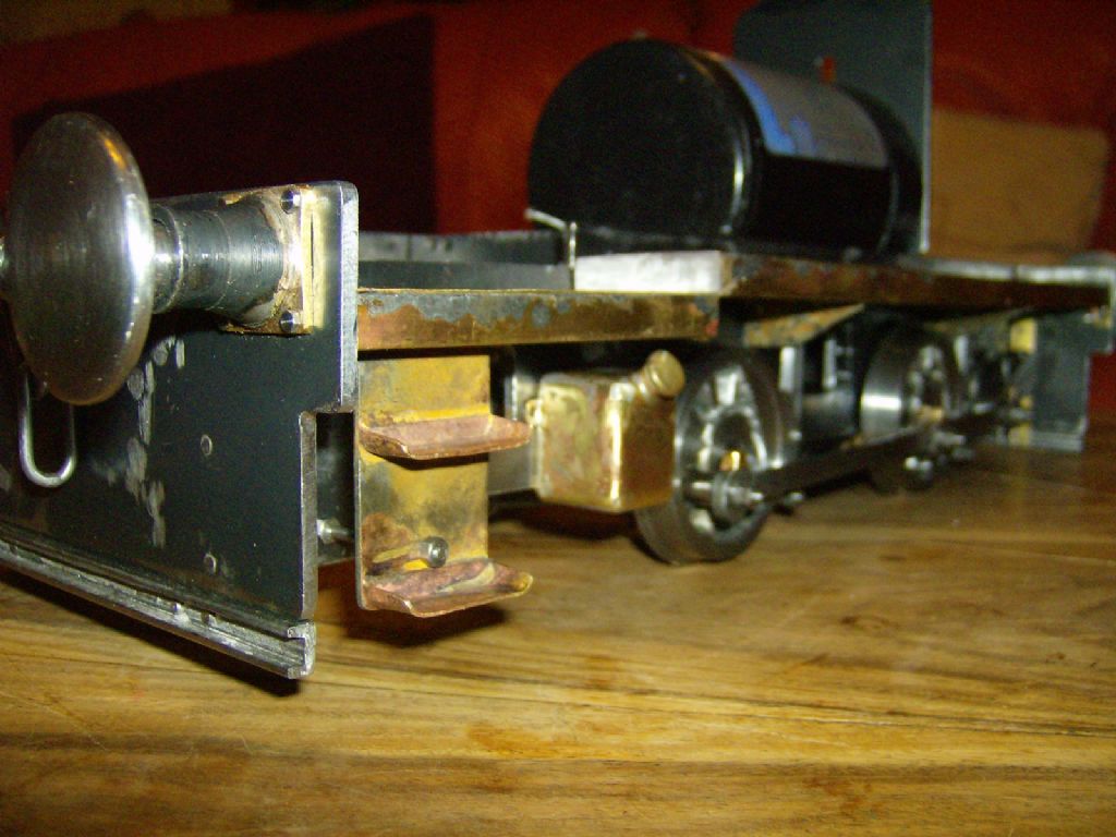
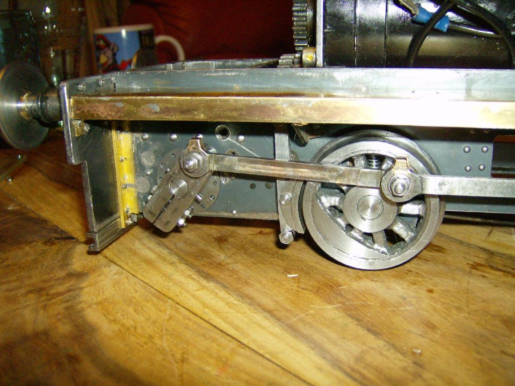
          From such small beginnings… not quite a might oak, but I now have a virtually complete chassis. I tweaked the connecting rods a bit (ok, I made two eccentric bushes to correct slight length errors). I haven't fitted the strong springs yet, as I don't yet know final weight. I need to rethink the brake gear as the front cross bar fouls one of the drive gears!

          A general view from the front:

          other bits

          And from the back (I like the steps, with their support rod and the sand tank from sheet brass):

          Back

          This is a detail of the crank, with dummy rivets around the 'hydraulic gearbox' – still some countersunk screws missing and to be filled. The running board has a frame from brass angle and steel brackets silver soldered up, and is the bit I struggled to solder a flat plate on top of:

          Chassis 3

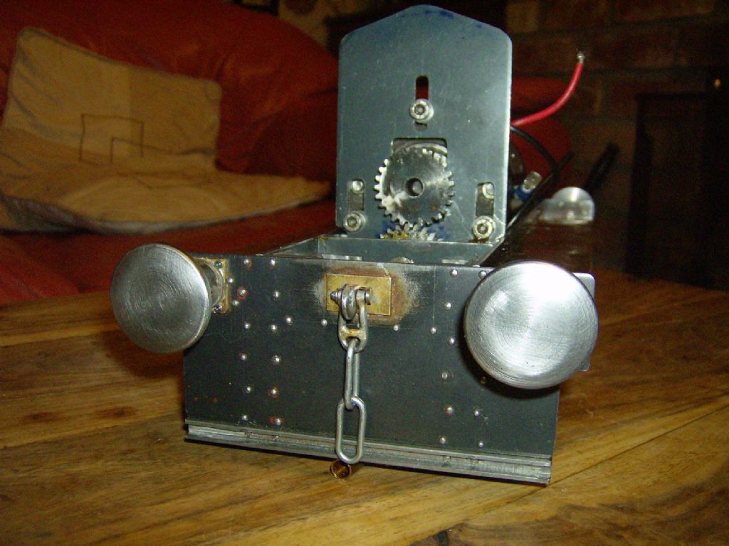
          This is the front – I had to remake the plate in the previous picture, it was too narrow:

          Front

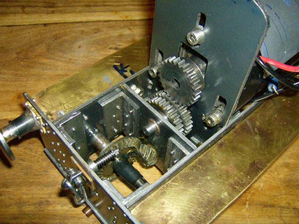
          This is the gearbox, with four home cut gears and bevels from a burnt out angle grinder. Note the slotted motor mount so I can change the gear ratio if it is over geared.

          Gearbox

          And this is the solenoid for the brakes. It will just pull them on gently at the same time as a relay shorts the motor for back-emf braking:

          Brake solenoid

          Neil

        Viewing 3 posts - 1 through 3 (of 3 total)
        • Please log in to reply to this topic. Registering is free and easy using the links on the menu at the top of this page.

        Advert

        Latest Replies

        Home Forums Locomotives Topics

        Viewing 25 topics - 1 through 25 (of 25 total)
        Viewing 25 topics - 1 through 25 (of 25 total)

        View full reply list.

        Advert

        Newsletter Sign-up