How Would I Machine this CAD designed Ratchet

Advert

How Would I Machine this CAD designed Ratchet

Home Forums CAD – Technical drawing & design How Would I Machine this CAD designed Ratchet

Viewing 17 posts - 51 through 67 (of 67 total)
  • Author
    Posts
  • #785861
    peter1972
    Participant
      @peter1972
      On JasonB Said:

      Any reason why the pawl can’t be rotated 90deg and act on teeth on the side of the wheel?

      Yes, that would be mechanically very much better but you would need a light spring instead of relying on gravity (assuming the axis of the wheel is gong to be vertical). It would avoid the end of the pawl having to slide on the wheel as it pushes.

      Advert
      #785864
      Nigel Graham 2
      Participant
        @nigelgraham2

        Just a daft question….

        Do the teeth really need be that shape? Would something like gear-teeth with straight flanks work?

        If so and the number is even you can simply cut the gullets straight across the diameter and add the core as a separate piece, or use a slot-drill if semicircular ends into the central boss don’t matter.

        What made me ask?

        The shaping-machine!

        The feed-ratchet on my Drummond hand-shaper resembles a pinion, but seems to have straight-flank teeth. The pawl is a rigid rod that reciprocates within a guide oscillating about the feed-screw axis. The tip is profiled to ramp it out of the gullet.

        So for your crown-wheel pattern, could the pawl be L-shaped with an appropriate asymmetrical bevel, reciprocating in a block restrained by a rotary spring, but which swings to let the pawl climb on the return stroke?

        No fancy teeth-shape, no unusual cutters or complicated machine setting; though if end-milled, I am not sure if offsets are needed for making the flanks chordal rather than radial.

        #785964
        Tomfilery
        Participant
          @tomfilery

          Ok Dave,

          I’m going to be slightly controversial here.  As you have managed to draw the item in 3D, why don’t you have it 3D printed in stainless steel (316 IIRC).  I reckon it will cost you about £40 (for a one off) of which about £25 will be postage (from China via DHL).  Visit the CraftCloud website.  I had some 16mm scale railway bogie side frames printed and it cost me £85 for 21 of them (they were roughly 75 x 20 x 10mm).

          For those who don’t know, you simply upload your 3D file, tell them how many you want and you get a list of around 100 different materials and prices for each one.  You can change quantities and materials until you get the best mix of cost/material to suit your pocket.  Once you’ve selected material and what finish you want, you hit the “go” button and pay.  Parts usually arrive within a week!  Absolute magic.  I’m a happy customer only and have no connection with the companies involved.

          Regards Tom

          #785974
          Michael Gilligan
          Participant
            @michaelgilligan61133

            It appears that Dave’s design  was inspired by Odometer mechanisms

            So those trying to assist might find these documents of interest:

            https://www.astro.unige.ch/~wildif/cars/docs/Smith-jaeger_speedo_repair.pdf

            http://www.wdbsa.nl/Jaeger-Chronometric-Overhaul.pdf

            MichaelG.

            #785977
            JasonB
            Moderator
              @jasonb

              A quick flick through that and all the ratchet wheels I can see have the teeth on the OD, as I suggested yesterday.

              Maybe Dave can show us some with the end face ratchet.

              #785983
              JasonB
              Moderator
                @jasonb
                On SillyOldDuffer Said:
                On JasonB Said:

                Dave, if you used the 26 ratchet teeth that you say you want rather than about half that,then you won’t get the big flat pie shaped top pieces.

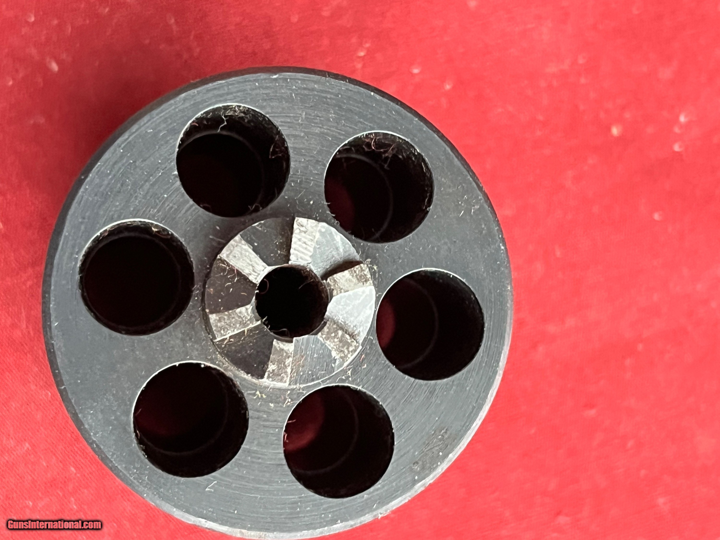
                Ah but remember I like to solve the general problem, not just one-offs.   Although my example calls for 26 teeth, if there is an answer, it should cover any number of teeth.   There’s an Enigma machine that only does digits, which would need a 10-toothed ratchet.  And a revolver needs 6.  The Germans dodged the problem on Enigma with a mechanism that doesn’t need a ratchet of the form I designed.  Might be because they looked at the geometry I’m asking about and decided it was too difficult to make.

                In which case, I might well be going back to the drawing board.

                Dave, I suggest you go to your first model in the openimng post and increase the cicular pattern to 26, it will make quite a difference and you will likely have to modify shape of the “cut”

                #786017
                SillyOldDuffer
                Moderator
                  @sillyoldduffer
                  On peter1972 Said:
                  On JasonB Said:

                  Any reason why the pawl can’t be rotated 90deg and act on teeth on the side of the wheel?

                  Yes, that would be mechanically very much better but you would need a light spring instead of relying on gravity (assuming the axis of the wheel is gong to be vertical). It would avoid the end of the pawl having to slide on the wheel as it pushes.

                  There is in the context of the much more complex machine of which this would be a part (see Enigma thread).   The arrangement of other parts make it easier to apply the pawl flat as shown in my opening post.   So although, it’s possible to turn the pawl through 90°, limited access means several other components have to be tweaked.

                  A number of comments that suggest changing the design assume Duffer is bonkers for wanting to do it this way.  Not so, the geometry works, and the configuration fits my use case.  My problem is how to cut the part in my humble workshop – lathe, milling machine, rotary table.

                  Another problem is the assumption that my example mechanism is complete.  It’s not!  To keep it simple, I show the pawl as being gravity operated.   The real one would have a spring, not least because the wheel operates sideways, and the pawl feeds from below, just above the machines base-plate.  Problem is a correspondent might  assume the absence of a spring is part of the problem, when it isn’t.    Providing a fully developed design is more work than I care to do, and with respect, is as likely to confuse as clarify:  more rabbit holes for people to explore, instead of tackling the exam question.

                  Keep it coming though, I#m getting plenty of value from this.   Notably, that, so far, no-one has explained how the gear might be cut.   (The form can be made with additive methods like 3D-printing, but apart from brazing my workshop can’t do that in metal.)

                  Off to the doctor now, perhaps my GP can help!

                  🙂

                  Dave

                  #786105
                  SillyOldDuffer
                  Moderator
                    @sillyoldduffer
                    On JasonB Said:
                    On SillyOldDuffer Said:
                    On JasonB Said:

                    Dave, if you used the 26 ratchet teeth that you say you want rather than about half that,then you won’t get the big flat pie shaped top pieces.

                    Ah but remember I like to solve the general problem, not just one-offs.   Although my example calls for 26 teeth, if there is an answer, it should cover any number of teeth.   There’s an Enigma machine that only does digits, which would need a 10-toothed ratchet.  And a revolver needs 6.  The Germans dodged the problem on Enigma with a mechanism that doesn’t need a ratchet of the form I designed.  Might be because they looked at the geometry I’m asking about and decided it was too difficult to make.

                    In which case, I might well be going back to the drawing board.

                    Dave, I suggest you go to your first model in the openimng post and increase the cicular pattern to 26, it will make quite a difference and you will likely have to modify shape of the “cut”

                    But that doesn’t cover my requirement  “ if there is an answer, it should cover any number of teeth.”  Did you miss that?

                    Also, I see no point in “Maybe Dave can show us some with the end face ratchet.”   Is the idea that failing to show ‘proves’ what I’m exploring is fundamentally wrong?   If so, that’s an unhelpful misunderstanding.

                    I’ve said it 3 or 4 times already, but the mechanism as presented in my opening post works.   The active part of the ratchet geometry is ‘good enough’.  But, exactly as you explained, the way the profile is generated creates a hard to cut double curve.  I already knew that!   My primary question is how to cut that double curve, not ‘is there another approach or bodge that gets a one-off done’.   If the answer is “it’s impossible”, then the alternatives become valuable.

                    And please don’t get hung up on odometers!   My opening post describes the requirement as “odometer-like”, and, in researching odometers for inspiration, I found similar examples.  That many odometers don’t have “flat ratchets” is irrelevant.   And as I said, the nearest example is the revolver,  isn’t that good enough?

                    Here’s the revolver example again:

                    Supplemented by this drawing of a Colt pinched off the web.  In it, part 4 carries a flat ratchet similar to mine, and it clocks cylinder 3 when pushed by pawl 17, which is attached to hammer 13.   The arrangement is no doubt decided by the needs of the rest of the gun’s mechanism.  Therefore the tool-room have to meet the design need, not question it, or suggest alternatives that allow part 4 to be made easily but require everything else to change.   I expect Samuel Colt sat down with his craftsmen and had a long discussion about this , and then the craftsmen came up with a way!

                    colt

                    Other examples have been mentioned by Michael and others: notably in clockmaking. Michael noted the earlier Verge topic failed to answer a similar question, so this is a difficult one.

                    Can I ask everyone to concentrate on the ‘how to cut it’ question first, rather than denying the need, or altering the use-case to suit a different approach?  Please accept that this gear form exists in the real-world, so how was it made?   Different approach may well be necessary, but not I’m not there yet.

                    I’ve tried two CAD methods to solve it.  One results in an easy to cut ratchet-like gear that doesn’t meet the requirement well, though it could be tweaked.  The other produces a gear that performs, but is hard to cut, maybe impossible.   Could be I’ve missed something in  Solid Edge that would produce a cut-able form that does meet all the requirements.   If it exists I haven’t found it yet!

                    I own a book that probably explain the geometry, but it’s a heavy theoretical read.  I was hoping someone in the team had experience, perhaps a tool-room guy involved in making moulds/jigs/fixtures for gas-meters or similar.   Or possibly a clockmaker or gun-maker.

                    Ta.

                    Dave

                    #786108
                    Michael Gilligan
                    Participant
                      @michaelgilligan61133
                      #786111
                      SillyOldDuffer
                      Moderator
                        @sillyoldduffer
                        On Tomfilery Said:

                        Ok Dave,

                        I’m going to be slightly controversial here.  As you have managed to draw the item in 3D, why don’t you have it 3D printed in stainless steel (316 IIRC).  I reckon it will cost you about £40 (for a one off) of which about £25 will be postage (from China via DHL).  Visit the CraftCloud website.  I had some 16mm scale railway bogie side frames printed and it cost me £85 for 21 of them (they were roughly 75 x 20 x 10mm).

                        For those who don’t know, you simply upload your 3D file, tell them how many you want and you get a list of around 100 different materials and prices for each one.  You can change quantities and materials until you get the best mix of cost/material to suit your pocket.  Once you’ve selected material and what finish you want, you hit the “go” button and pay.  Parts usually arrive within a week!  Absolute magic.  I’m a happy customer only and have no connection with the companies involved.

                        Regards Tom

                        Not at all Tom!  I spotted early on that an additive process could do the job, and that the model could be sent off.  You’ve added much value by identifying a supplier and the likely cost!  At the moment I’m still pursuing the ‘can I cut it at home’ route, and the educational value.   But your numbers suggest a better answer is to do the design, accept that an additive process is needed and affordable, and have it made elsewhere.  I don’t have to worry about form cutters etc.

                        We live in an interesting world.  In 1948, marvellous things were done with little more than a Myford and basic hand-tools applied skilfully. Now I could CAD model an entire LBSC loco and have all the parts made professionally, not too expensive, and very quick compared with my slow workshop.   But making things myself is fun…

                        Thanks,
                        Dave

                        #786123
                        SillyOldDuffer
                        Moderator
                          @sillyoldduffer
                          On Nigel Graham 2 Said:

                          Just a daft question….

                          Do the teeth really need be that shape? Would something like gear-teeth with straight flanks work?

                          Not daft at all.  But so far no-one has identified ‘something like gear-teeth with straight flanks‘ that meet the requirement.  The geometty is problematic, either easy to cut, but not the right shape, or close to the right shape, but made with a hard to cut double curve.   I’ve not found a way of eliminating the double curve!

                          What made me ask?

                          The shaping-machine!

                          Yup, I don’t own one but my lathe could be set-up to replicate.

                          The feed-ratchet on my Drummond hand-shaper resembles a pinion, but seems to have straight-flank teeth. The pawl is a rigid rod that reciprocates within a guide oscillating about the feed-screw axis. The tip is profiled to ramp it out of the gullet.

                          A photo would be most welcome pretty please!

                          So for your crown-wheel pattern, could the pawl be L-shaped with an appropriate asymmetrical bevel, reciprocating in a block restrained by a rotary spring, but which swings to let the pawl climb on the return stroke?

                          Yes, except the existing design constrains what can be done.   A number of suggestions fail because they assume I’m able to change everything else!   I could, but the pawl/wheel arrangement I’m asking about avoids the need to re-engineer several other interrelated components.   Also, to keep it simple, my partial example, implies the pawl is gravity operated.   The real one is sideways on compared with my example, and would have a spring.

                          No fancy teeth-shape, no unusual cutters or complicated machine setting; though if end-milled, I am not sure if offsets are needed for making the flanks chordal rather than radial.

                          Hopefully yes, but I don’t know how to do that in practice, though some good compromises have been suggested.   If you fancy a change from your Steam Wagon, have a go in Alibre.  I’d be delighted to see a tooth form that’s easy to cut AND close to the requirement.

                          State of play this morning, is, if this had to be made in my workshop now, I’d have to accept a compromise.   But I’m not convinced that something along the lines you suggest is impossible, if only I understood the geometry better…

                          Dave

                          #786141
                          peter1972
                          Participant
                            @peter1972

                            Instead of cutting teeth, cut a narrow zigzag channel around one side of the wheel using CNC with 26 ‘zigs’. Put a pin on the end of the actuator which engages with the channel in a similar way to a push-push or push-latch mechanism.

                            #786161
                            JasonB
                            Moderator
                              @jasonb

                              If you are going the CNC route then you may as well just machine the compound curve, it’s only a 3D surface. But it will require small fillets in the internal corners of each cutout.

                              Dave if you want to put the full 26 teeth onto your original and send it to me as a STEP file I’ll show how close it can be got in my workshop.

                              The revolver looks to have “flat” ramps which are easy enough to do. Two I did earlierone with the mill one with a file.

                              DSC00943

                              DSC00185

                              #786172
                              Michael Gilligan
                              Participant
                                @michaelgilligan61133

                                It’s maybe worth having a look at:

                                https://worldwide.espacenet.com/patent/search?q=pn%3DGB189515453A

                                MichaelG.

                                .

                                IMG_0638

                                #786188
                                Michael Gilligan
                                Participant
                                  @michaelgilligan61133

                                  … and something much more recent, with excellent line-drawings, here:

                                  https://worldwide.espacenet.com/patent/search?q=pn%3DUS2011083351A1

                                  MichaelG.

                                  #786194
                                  Michael Gilligan
                                  Participant
                                    @michaelgilligan61133

                                    Seven minutes into this shows the ratchet pretty well:

                                    https://youtu.be/ETHTCr6HAUs?feature=shared

                                    … and lots more towards the end

                                    … but of course still doesn’t show how to make it 🙁

                                    MichaelG.

                                    .

                                    #786205
                                    JasonB
                                    Moderator
                                      @jasonb

                                      Well this is as close as I could machine to Dave’s original sketch on the CNC with a long neck 2mm ball nose cutter. I don’t know the radius of curved slope “A” so just put something in but it does reduce as it gets closer to the ctr of the wheel. This is 50mm diameter and depth of tooth proportioned to what was shown

                                      I could send you the G-code Dave, then you could convert it into a series of co-ordinates which could be done on your manual machine.

                                      Angles and tooth depth change a lot for the same given diameter when the number of teeth are doubled to 26 which will affect teh size and action of the pawl.

                                      daves ratchet

                                    Viewing 17 posts - 51 through 67 (of 67 total)
                                    • Please log in to reply to this topic. Registering is free and easy using the links on the menu at the top of this page.

                                    Advert

                                    Latest Replies

                                    Viewing 25 topics - 1 through 25 (of 25 total)
                                    Viewing 25 topics - 1 through 25 (of 25 total)

                                    View full reply list.

                                    Advert

                                    Newsletter Sign-up