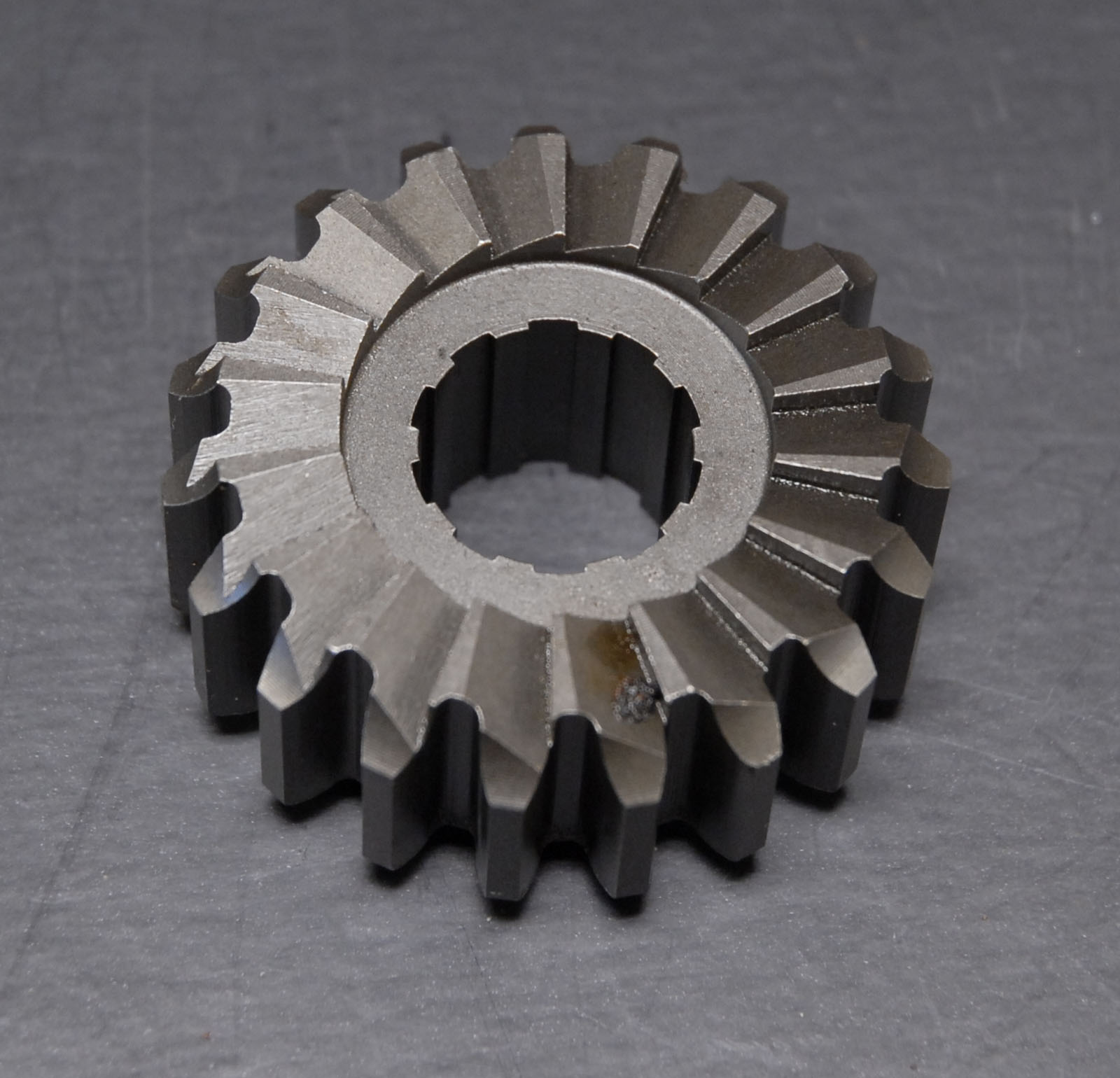
Only interrupted 4 times, though the work is taking longer than expected.
First off, made a blank with a big hole in the middle, as suggested, and added a tangent plane. (In addition to the usual XY, XZ, and YZ planes, CAD allows tangent and angled planes as well.)

The 2D sketch representing the cutter is drawn on the tangent plane and can be projected into the blank in various ways. I experimented with straight cutting at 90° and then with projecting the sketch onto the curved blank and letting the software cut at a diverging angle to an edge on the Z-axis.
Straight cut with a 45° form tool (as typical in a milling machine) produces:

And repeating it with a rotary table would give:

Though easy to make, the result is no good. Tilting the job (or mill head) to 26°and going deeper, looks better:

but it’s another fail. On the outer edge the pawl has to climb over 12mm, whilst only 5 on the inside. Not ideal – the pawl should climb roughly the same height wherever happens to be.
Next I tried altering the cutter form, in this example to a round rather that straight 45° V. This could be done with a shaped grinding wheel. There’s no advantage in the yellow curves and the flat triangular tops spoil the pawl’s action.

Next, the V is projected on to the cylinder, changing shape, and doesn’t cut from the tangent at 90°.

The top is flat, hurrah, and cutting deeper narrows the top to the desired nearly parallel edged form, shown in red below. The pawl rises and drops consistently:

But the yellow face is hard to cut because it’s profile curves right-left and in-out simultaneously. That seems to require a cutter that changes shape and angle depending where is it. Spark erosion or a laser.
Need to explore further, cos I don’t understand this properly, but it feels like the best answer is one of: 3D-printing a mould and casting it; 3D-printing it in plastic and hoping it’s strong enough; sending the file off to a 3D metal printer and having them make it; or sending it to a CNC shop who does sparks, lasers, and tiny cutters. So far no sign of a way of doing this in metal with the equipment I have.
Oh, and as a few correspondents have pointed out, the pawl’s profile should match the ratchet.
Back to the drawing board is still an option, and I’m not convinced I’ve investigated Peter’s suggestion sufficiently.
Dave
 JasonB.


 more like the animal you are looking for. This one would, I think, work with the starting position of the push faces square, and moving right from there.


