How to test a Myford ML7 spindle?

Advert

How to test a Myford ML7 spindle?

Home Forums Manual machine tools How to test a Myford ML7 spindle?

Viewing 16 posts - 1 through 16 (of 16 total)
  • Author
    Posts
  • #616160
    Jon Halland
    Participant
      @jonhalland84811

      I have now finished cleaning up the ML7 and starting to put it back together. Currently its final placement is not decided, so this is just standing on the workbench. This is my first lathe and I'm trying to learn how to test and set this oldie up.

      Testing the bed: I've measured the width of the front bed that the carriage align to. Left from 0'' to 12'' in 1'' steps, all measurements using a 2'' micrometer are in the range 1.748''-1.749''. So max 0.001'' difference/wear, I guess that is fine?

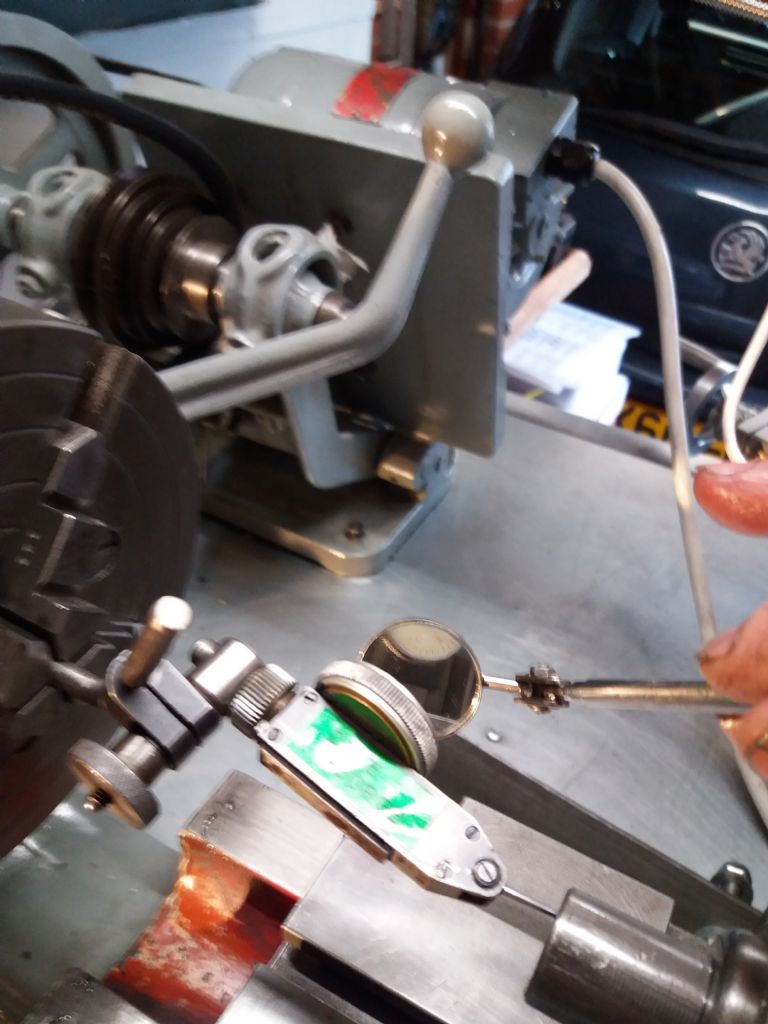
      Headstock Alignment: I got a new MT2 test bar (spec 0.001'' ) to do headstock alignment, mounted the carriage/apron tightly but still movable, using a dial indicator (0.0005'' resolution) I adjusted the headstock and tightened it down. With 0 and the start of the test bar I got 0.0015'' at 6''. But when turning the spindle I got 0.007'' run out – not good!

      Test bar test: I marked the spindle and test bar and noted the spindle position, then moved the carriage with the dial indicator so I could turn the test bar 180 deg and repeat the test. Result 0.0075'' run out with the spindle in the same position. So the test bar is straight and within spec, which indicate the headstock spindle/bearings has 0.007'' run out.

      I've shimmed and tightened the bearings to snug but turnable by hand.

      How do I progress and test the spindle and bearings?


      Edited By Jon Halland on 05/10/2022 23:20:23

      Advert
      #14672
      Jon Halland
      Participant
        @jonhalland84811
        #616162
        Anonymous

          Posted by Jon Halland on 05/10/2022 23:19:30:

          …which indicate the headstock spindle/bearings has 0.007'' run out.

          Could be that the spindle is fine but the test bar is not seating properly in the headstock taper.

          Andrew

          #616164
          peak4
          Participant
            @peak4
            Posted by Andrew Johnston on 05/10/2022 23:26:14:

            Posted by Jon Halland on 05/10/2022 23:19:30:

            …which indicate the headstock spindle/bearings has 0.007'' run out.

            Could be that the spindle is fine but the test bar is not seating properly in the headstock taper.

            Andrew

            Not that I'm any expert, but it would be my first point to check.
            Do you have any blue, the greasy stuff, not layout blue.
            At a pinch you could try a tiny bit of lipstick.

            Bill

            #616204
            Hopper
            Participant
              @hopper
              Posted by Jon Halland on 05/10/2022 23:19:30:

              Testing the bed: I've measured the width of the front bed that the carriage align to. Left from 0'' to 12'' in 1'' steps, all measurements using a 2'' micrometer are in the range 1.748''-1.749''. So max 0.001'' difference/wear, I guess that is fine?

              Headstock Alignment: I got a new MT2 test bar (spec 0.001'' ) to do headstock alignment, mounted the carriage/apron tightly but still movable, using a dial indicator (0.0005'' resolution) I adjusted the headstock and tightened it down. With 0 and the start of the test bar I got 0.0015'' at 6''. But when turning the spindle I got 0.007'' run out – not good!

              Test bar test: I marked the spindle and test bar and noted the spindle position, then moved the carriage with the dial indicator so I could turn the test bar 180 deg and repeat the test. Result 0.0075'' run out with the spindle in the same position. So the test bar is straight and within spec, which indicate the headstock spindle/bearings has 0.007'' run out.

              I've shimmed and tightened the bearings to snug but turnable by hand.

              How do I progress and test the spindle and bearings?

              Edited By Jon Halland on 05/10/2022 23:20:23

              The first thing you need to do is wait until 30 minutes or more after sunset when it is good and dark. Stand outside your workshop door and lick you finger and hold it up to determine which way the wind is blowing. Then throw that bloody test bar as hard and far in that direction as you can. Those things cause more problems than they solve, particularly in the sweaty hands of beginners.

              And you need to separate headstock alignment from spindle runout. Two different things. Alignment is setting the lathe headstock and spindle in line with the lathe bed's central axis. Runout is the reading you get with a dial indicator when rotating something. If it is running eccentrically, you have runout.

              A Myford headstock never needs realigning with the bed, under normal circumstances. It is done at the factory by trained fitters who set it up metal to metal, scraped to align it. No shims used.. If you return your headstock to its original position with the jacking bolts so the headstock metal is pressed up against the bed metal, it's aligned.

              Now, if you want to set your lathe up to turn parallel (without a tailstock centre), do what we all do when all else fails: read the instructions. The Myford ML7 Users Manual gives a thorough run through on how to shim or adjust the lathe bed to bench mounting points to twist the bed slightly to make it turn parallel. You don't need to use a fancy level, and especially not a fancy test bar. It is done by taking test cuts over a piece of 1" diameter x 4" long steel bar and measuring the diameter at each end. You then shim or adjust the lathe bed feet at the tailstock end to make it turn parallel. Simple as anything. The ML7 User Manual is widely available for free download on the internet. It has all you need to know about aligning your headstock spindle to the bed.

              On your million-year-old lathe, the internal Morse taper in the headstock spindle is almost certainly scarred up, butchered, abused or othewise out of whack enough to make it run out of true. And the spindle can even have developed a slight bend over the countless eons since is left Beeston. Mounting a fancy test bar in there tells you nothing, as you have found out.

              Re your bed measurements, you are on the right track there, if you lathe is a pre-1972 narrow guide model that uses both vertical sides of the front way to guide the carriage. One thou of wear is very good. Three thou is Myford's recommended limit before regrinding. The thickness of that front way measured vertically is allowed a couple of thou more as it is less critical.

              BUT, if your ML7 is post-1972 or has been converted to wide-guide configuration, it uses the front of the front way and the rear of the rear way, so you need a 4" micrometer to measure that overall distance to get a true reading of wear.

              I thought I had a pic of that manual page on alignment to post but don't seem to be able to find it. But you can fiund the manual all over the net.EG the Myford lathes group on groups.io in the Files section.

              #616210
              Hopper
              Participant
                @hopper

                Here is what the User Manual says on setting up your Myford to turn parallel. That's all you need to do.

                d5cdc7ad-1ea0-479c-9c51-1bec74a0687f.jpeg

                33c91336-9d94-4b20-9f51-1df6010bf205.jpeg

                .

                #616219
                Brian Wood
                Participant
                  @brianwood45127

                  Well said Hopper, good and to the point

                  Brian

                  #616221
                  Jon Halland
                  Participant
                    @jonhalland84811

                    Thanks for your great replies, specially to Hopper for the very thorough reply and manual pics.

                    I was in the workshop this morning and can confirm your suspicion that the MT2 fit is the first to work on. When looking closer at female MT2 on the spindle I can see lots of wear marks and with a nail feel nicks on the edge. So I took a fine emery cloth and just cleaned up the edge a bit and repeated the runout test at 6'' with the test bar at 0, 90, 180, 270 deg. The runout was reduced to 4 thou and always with the spindle in the same position, so there is a high spot to be removed. I can also see very fine scratches on the polished male taper on the test bar on the last 10mm (fat end) that connects the to the spindle. The spindle taper could do with a clean up, its an old non hardend type. I have fine emery cloth, 1200 and 2000 vet and dry paper and Autosol, is this OK to try with or a no-go? Or is it possible to get a male MT2 shaped polishing thing to use by hand? I do not have a MT2 reamer and would not be confident to use one on the spindle until after the lathe is proper setup and tailstock aligned.

                    #616222
                    duncan webster 1
                    Participant
                      @duncanwebster1

                      Unless you want to use MT collects in the spindle the runout of the taper doesn't matter. As long as it grips you can skim and indeed should skim the taper in situ every time you use it. I wouldn't go attacking it with abrasives, not localised enough

                      #616307
                      Jon Halland
                      Participant
                        @jonhalland84811

                        Duncan: I do have a set of collets and a milling slide with a T slot plate, so just need some end flute cutting bits……

                        Hopper: just read some of your older posts on cleaning up tapers – thank you for your many knowable replies.

                        #616440
                        Howard Lewis
                        Participant
                          @howardlewis46836

                          Have you checked that the test bar is not bent>?

                          Set it between centres and run the DTi along it (This assumes that the gibs on the saddle are set to give minimum clearance. No point in doing any checks if they are not )

                          If the bar is bent, the DTI reading will may well increase and then decrease as it approaches, crests and then passes the bend.

                          Might be worth carrying out this check with the bar rotated by 90 degrees relative to the first check.

                          Having established that the bar is acceptably straight , < 0.0005", CAREFULLY clean up the tapers, internal and external. To be sure, use marking blue, (Not layout blue ), to confirm optimum contact between bar and spindle bore.

                          When this satisfactory, the straight alignment bar can be used to adjust the Headstock so that the spindle bore is parallel to the axis of the bed ways.

                          Once this has been done, the the b lathe can be used to remove twist from the bed, as per the Myford manual.

                          Once all seems to be in order, the Alignment bar can be fitted between centres and used to align the tailstock..

                          This post reads like a cautionary tale..

                          Hopefully, anyone reading this thread and tempted to take apart their lathe,may like to consider if they have the knowledge, skill, and equipment to take on such an exercise..

                          It is far too easy to strip a reasonably accurate machine and make it into a very costly doorstop!.

                          Stripping and reassembling a lathe or any machine tool is not a task for the overconfident and under skilled!

                          There are many skilled and time served Engineers who would think very seriously before taking on such a task!

                          Howard

                          #616633
                          David George 1
                          Participant
                            @davidgeorge1

                            I set up my lathes with a 25mm piece of silver steel. I mount it in the four jaw chuck to run true at the chuck end and then tap the other end till it runns true as well. I then repeat til both ends run true. You can set a disk indicator on center height and run it back and forward to check bed true to spindle without wondering if spindle taper is damaged or run ing true. Repeat along top of bar to check height true running. Adjust bed clamps to adjust to run true. I then Mont a dial indicator on a stem in the chuck and allow the tip to run in the inside of the Morse taper of the tailstock and rotate the chuck to see if it is centred and adjust as nessesary.

                            clock up bar.jpg

                            clock up bar 2.jpg

                            clock taper 3.jpg

                            I always get a true parallel cut and drill on center.

                            David

                            #617185
                            Jon Halland
                            Participant
                              @jonhalland84811

                              I did a gentle clean of the spindle taper with fine emery cloth and a straight round plastic pencil to hold it down. I slowly turned the spindle 5-6 revs and lightly moving the pencil back and forward on the taper. After two treatments the runout was down to just under 2 thou at 6''. A third go did not improve the result. I will test with micrometer blue when I have found some pictures online as a reference of poor/good fit. Measurements of runout at 0-8'' in 1'' step were: 0.5 / 0.6 / 0.9 / 1.2 /1.5 / 1.6 / 1.8 / 2 / 2.2 thou, readings on a 0.0005'' resolution DTI. The taper could probably do with a reamer clean up.

                              Howard, thanks for the good points to be aware of.

                              The gib screw are set fairly tightly for these tests, when I use two hands and try to twist the saddle in the horizontal plane I get just under 0.5 thou movement.

                              To test if the test bar is bent I have run the DTI along it mounted in the spindle MT2 and the 4 jaw chuck. I have not seen increase/decrease/increase pattern on the dial, only a steady increase, so along with the consistent increasing runout measurements, my take is that the bar is fairly straight.

                              David, thanks for your reply, I'm still playing around with the 4 jaw chuck. I will get back when I'm happy with my measurements. Great pics, thanks. Do you know if the swivel clamp that connects the 2 rods on the last pic of the DTI has a specific name?

                              Jon

                              #617358
                              David George 1
                              Participant
                                @davidgeorge1

                                Hi John I was always told it was a knuckle union. They come in various sizes to match what you are holding and supporting with. The one in the picture is a 6mm to 6mm one.

                                This could be used

                                https://www.chronos.ltd.uk/product/imperial-dial-test-indicator-with-adjustable-holder/

                                David

                                #617403
                                peak4
                                Participant
                                  @peak4

                                  Jon, I don't know if you've read this thread on the subject of test bars, but it's worth perusing, as is the link Ketan provided to a previous thread as well
                                  https://www.model-engineer.co.uk/forums/postings.asp?th=183626

                                  Bill

                                  #617979
                                  Jon Halland
                                  Participant
                                    @jonhalland84811

                                    Sorry for the late reply… the spell of decent weather prompted a garden and shed clean up, but today is proper miserable, so I'm doing a bit in the workshop.

                                    I made a blue test on the spindle taper using the test bar, see pic. The big blob is a very accurate impression of the dent in the spindle taper and also show that there is still some high rim to be polished out. I will post another pic when I get it sorted.

                                    Dave: thanks for your reply, knuckle union gave a lot of references to some trash metal band and implements to connect to someone's ribs. Knuckle Clamp is a more peace full term. smiley

                                    I have a DI and a DTI and 2 old Eclipse magnetic stands the one is 1/2'' to 1/4'' and the other 12mm to 10mm (but with a 9.5mm bar, so not a great fit that twists a bit when tightened). The DTI has it's own knuckle clamp 11/32'' to 1/4''. It would be nice to have just one setup with interchange ability – future project!

                                    peak4: great thread, thanks for bringing it to my attention.

                                    pxl_20221020_110347688.jpg

                                  Viewing 16 posts - 1 through 16 (of 16 total)
                                  • Please log in to reply to this topic. Registering is free and easy using the links on the menu at the top of this page.

                                  Advert

                                  Latest Replies

                                  Home Forums Manual machine tools Topics

                                  Viewing 25 topics - 1 through 25 (of 25 total)
                                  Viewing 25 topics - 1 through 25 (of 25 total)

                                  View full reply list.

                                  Advert

                                  Newsletter Sign-up