How to strip a Centec 2A Vertical Milling Head

Advert

How to strip a Centec 2A Vertical Milling Head

Home Forums Workshop Tools and Tooling How to strip a Centec 2A Vertical Milling Head

Viewing 15 posts - 26 through 40 (of 40 total)
  • Author
    Posts
  • #473282
    Simon Williams 3
    Participant
      @simonwilliams3

      OOPS!

      Think I've got my lefty-loosies in a tangle. My apologies.

      Bill's put it straight – thank you.

      <2/10, could do better>

      Simon

      Advert
      #473284
      Avon
      Participant
        @avon

        Gentlemen,

        Firstly, many thanks for all your efforts, information and advice. It has all been useful and the photos of the drawbar arrangement will inform my manufacture of a replacement.

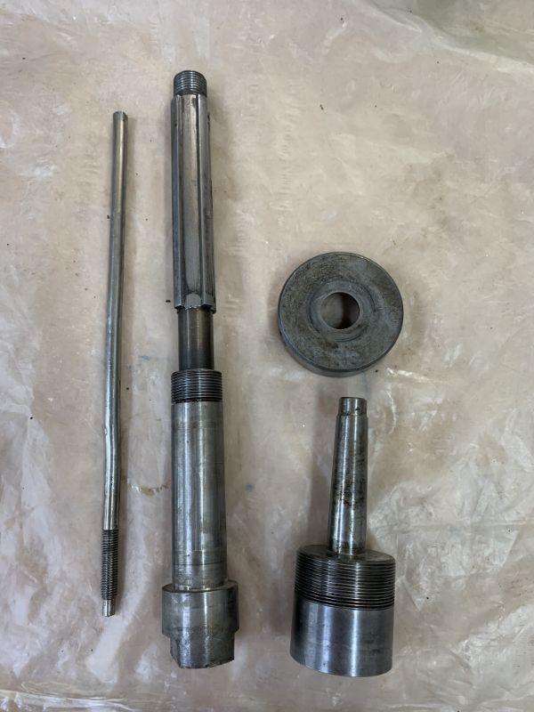
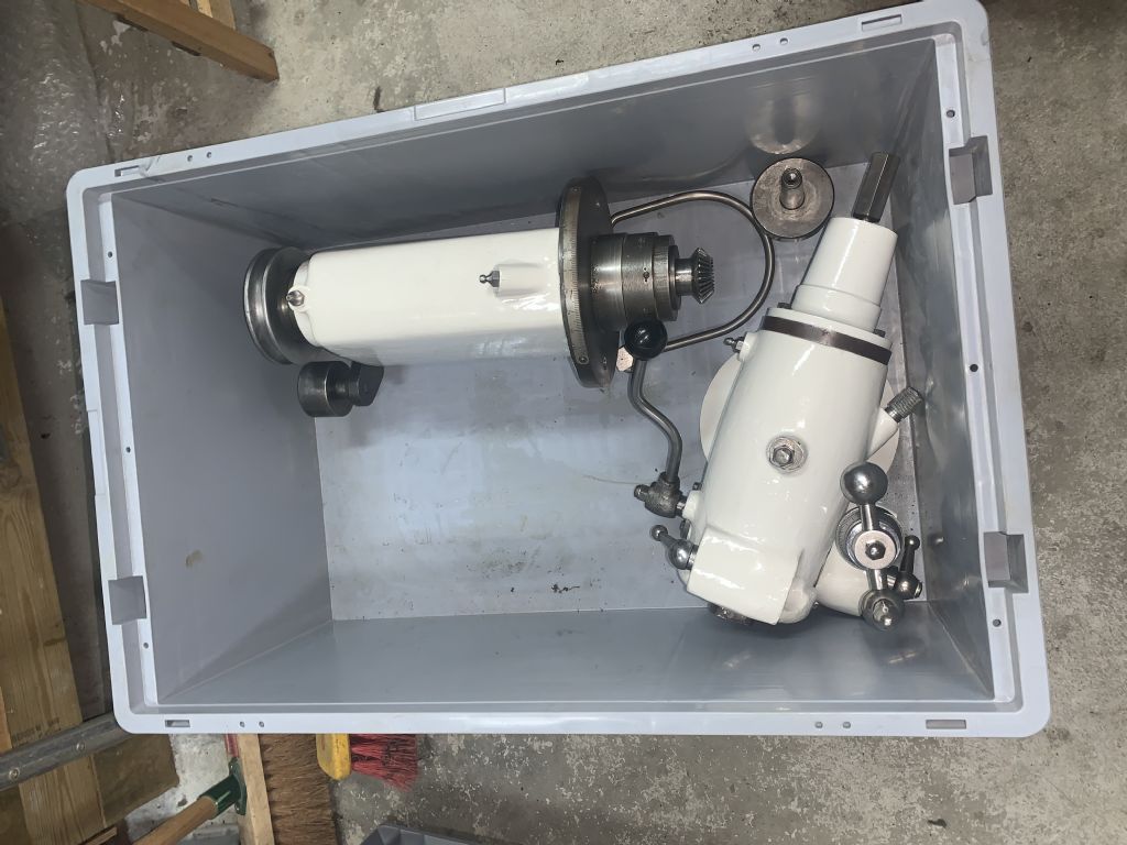
        Below is a photo of the thing apart.

        In the end I took it to an agricultural repair shop as the chap is frequently called on to renovate/repair machinery that has been hard used and unloved. It transpired that the ring/snugging nut was almost certainly in contact with the rear face of the chuck, so I was unable to gain further clearance between it and the end of the spindle which I is what I'd tried to achieve in the earlier photos. So we turned in as shown in Peak4's photo until it bore against the bottom of the spindle – it took a considerable effort to move the nut and a man sized spanner stopping the spindle moving which was clamped in jaws of a large Colchester lathe. We then tried heating it, but it made no difference. So back in the lathe and with some more enthusiastic hammering on the spanner until it finally came apart.

        The snugging nut is a nice clean thread so I'm sure it was just very tight up on the body of the chuck. The drawbar takes a meandering path from one end to the other, no wonder it wasn't very useful. The taper on the chuck seems to be nice and clean, but that in the quill has clearly had swarf and other inappropriate things in it. I'll have to get an MT2 taper reamer to clean it up.

        Gents, again thank your for you help – it gave me confidence in what we were doing and a successful outcome.apart.jpg

        PS. Why is it so difficult to work out a lefthand thread when we understand a righthand without thought!

        #473285
        Avon
        Participant
          @avon

          Gentlemen,

          Firstly, many thanks for all your efforts, information and advice. It has all been useful and the photos of the drawbar arrangement will inform my manufacture of a replacement.

          Below is a photo of the thing apart.

          In the end I took it to an agricultural repair shop as the chap is frequently called on to renovate/repair machinery that has been hard used and unloved. It transpired that the ring/snugging nut was almost certainly in contact with the rear face of the chuck, so I was unable to gain further clearance between it and the end of the spindle which I is what I'd tried to achieve in the earlier photos. So we turned in as shown in Peak4's photo until it bore against the bottom of the spindle – it took a considerable effort to move the nut and a man sized spanner stopping the spindle moving which was clamped in jaws of a large Colchester lathe. We then tried heating it, but it made no difference. So back in the lathe and with some more enthusiastic hammering on the spanner until it finally came apart.

          The snugging nut is a nice clean thread so I'm sure it was just very tight up on the body of the chuck. The drawbar takes a meandering path from one end to the other, no wonder it wasn't very useful. The taper on the chuck seems to be nice and clean, but that in the quill has clearly had swarf and other inappropriate things in it. I'll have to get an MT2 taper reamer to clean it up.

          Gents, again thank your for you help – it gave me confidence in what we were doing and a successful outcome.apart.jpg

          PS. Why is it so difficult to work out a lefthand thread when we understand a righthand without thought!

          #473333
          old mart
          Participant
            @oldmart

            Congratulations, it is such a relief to have it dismantled at last. The male taper looks ok, a little rust was expected. The drawbar thread looks a bit odd, I was expecting a 3/8 Whitworth and yours looks finer. You may have to make three drawbars, that mystery thread, a 3/8 W and a 10mm, to suit whatever tooling is fitted.

            #473339
            duncan webster 1
            Participant
              @duncanwebster1

              This might be a very bad idea, so give it a lot of thought before attempting! The drawbar is 3/8" BSW, you can still get tooling to fit, but M10 is a lot easier. I'm told that 10mm wont go down the hole in the spindle, but it's only 0.019" bigger. Could it be opened up? As I say this might weaken it so don't jump in. And of course your Autolock won't then fit

              #473341
              old mart
              Participant
                @oldmart

                The bore of these spindles varies but very probably a length of 10mm studding would go down a tight one as the threads usually measure a little smaller than nominal.

                When I modified the Tom Senior from MT2 to R8, I used the top half of the original spindle. The bore was over 10mm, but not quite 7/16" which is 11.1mm. Fortunately, I managed to ream it to 7/16" after silver soldering an extension onto the reamer.

                There looks like there is plenty of meat in the smallest diameter of that Centec spindle to make the bore a bit bigger if it is a tight one.

                I would give the MT2 taper reamer a miss, if I was you, that taper must be pretty good to have been such a pig to separate. 

                Edited By old mart on 20/05/2020 18:33:08

                Edited By old mart on 20/05/2020 18:36:16

                #473344
                Steviegtr
                Participant
                  @steviegtr

                  Hi Avon, glad you got it done. I have been following this thread as I have the same autolock with the MT2 stabiliser ring. yes

                  Steve.

                  #473361
                  not done it yet
                  Participant
                    @notdoneityet

                    My drawbars are all threaded rod. May need four (or more) for the Centec.🙂. There are eight different ones in my workshop. Could be ten if I ever need the smallest MT in the Centec and an imperial one for the lathe (very doubtful).☹️
                     

                    As scribe, or similar, run in the visible threads is a good way to check if you are not sure…

                    Edited By not done it yet on 20/05/2020 19:26:38

                    #473427
                    peak4
                    Participant
                      @peak4

                      I've not got around to this mod for the Centec drawbar yet, so this is just a proposal.

                      My other mill is a Dore Westbury with a thinner drawbar. That one is a length of 8mm rod with a 1/4 BSW section on the end. Most of my MT2 tooling is tapped 3/8 BSW. I then use a small slug externally threaded 3/8" and internally 1/4", which allows enough wall thickness for strength.

                      The newer/cheaper tooling is M10, so I just use a different slug in the end of the taper to adapt to the 1/4" BSW drawbar thread.

                      The intention is to make up a new self ejecting drawbar of of something like EN8 with a 14" BSW stud in the end to adapt to each of my MT2 chucks, cutters. etc.
                      Hence no need to have multiple drawbars for the Centec, just an adaptor in the MT2 tooling.
                      The only thing you would need to watch out for with the arrangement, is the tooling unscrewing from the adaptor, rather than the drawbar unscrewing from it.

                      Not a problem with the Centec, as the bore is big enough for 3/8", but a pain with the Westbury with the smaller bore. If M10 doesn't fit the Centec bore, then a screwdriver slot in the tooling end of the adaptors might be a good idea, as unlike the Westbury, the drawbar on the Centec can't be dropped down due to the self eject collar.


                      Bill

                      Edited By peak4 on 20/05/2020 23:28:03

                      #477746
                      Avon
                      Participant
                        @avon

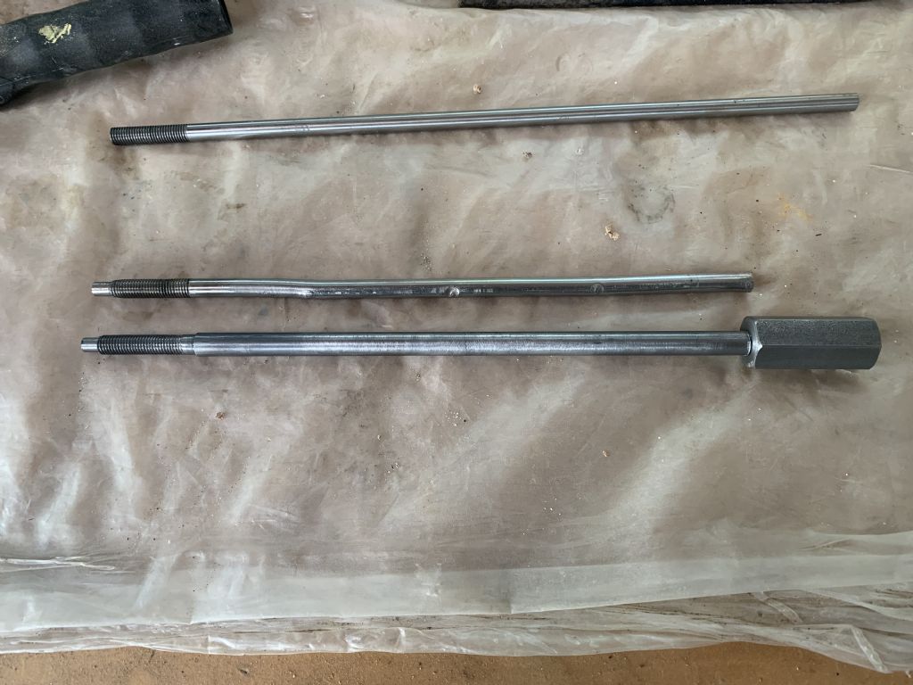
                        Finally produced a new drawbar. Turns out the thread on the original was 5/16 BSF (22tpi). So I've turned down a length of 3/8 and threaded it. I've added a length of Hex bar to the top with a 3/8BSF (20tpi) and will also drill and pin it when I can. The 3/8 rod is a firm fit in the quill, but I can turn it fairly easily with fingers so don't think it will cause any problems and should transmit any stout taps without too much flexing.

                        Its not at all sophisticated, but I think it will suffice and if I need to make another at least I now know how.

                        Many thanks for all your help and ideas.photo 05-06-2020, 17 08 50.jpg

                        #477776
                        old mart
                        Participant
                          @oldmart

                          As long as plenty of thread goes into the end of the tooling, it will withstand the shock of breaking the taper very well. If you later decide to reduce the diameter by a few thousandths of an inch, it could best be done in three or four stages in the lathe. Start by putting a centre in the hex end for tailstock support and it won't matter if the overlaps show.

                           Steel for drawbars can be made from en16t or en24t they both machine quite well.

                          Edited By old mart on 05/06/2020 20:20:50

                          #487874
                          duncan webster 1
                          Participant
                            @duncanwebster1

                            Avon,

                            If you haven't already got it back together, could you count the teeth on the 2 bevel gears for me. I'm trying to establish the ratio between the horizontal drive shaft in the vertical head and the spindle

                            #487883
                            Avon
                            Participant
                              @avon

                              Hi Duncan,

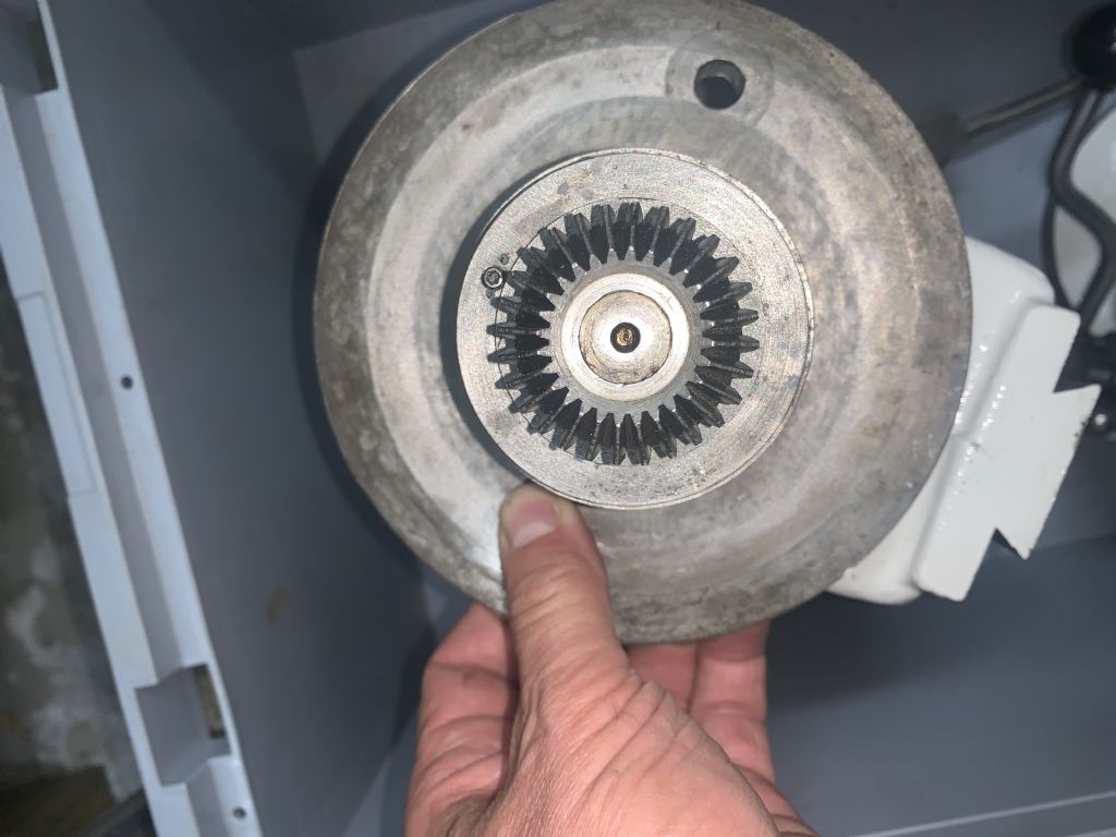
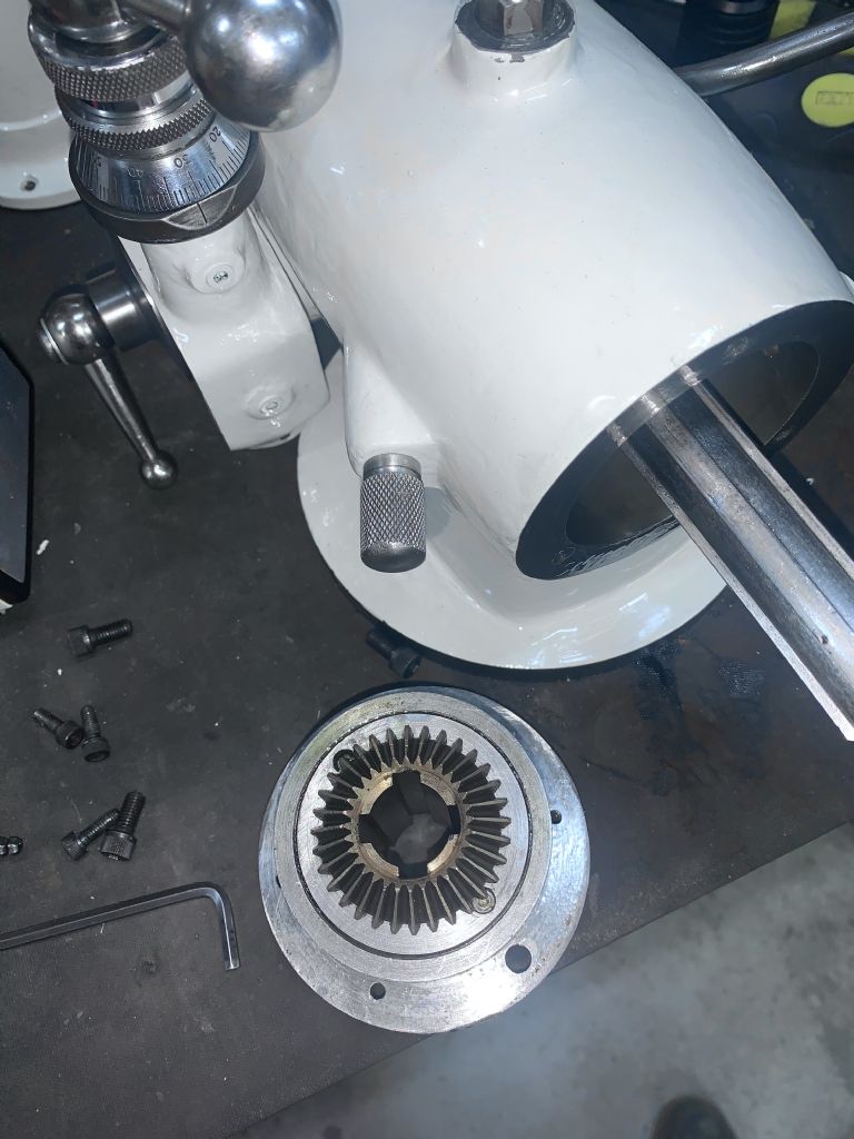
                              I counted 28 on the driving shaft and 32 on the driven. By my calcs that gives approx 15% reduction in speed of 1600 input shaft and 1400 at the quill. Photos below:

                              Hope that helps.

                              photo 27-07-2020, 22 04 07.jpg

                              photo 27-07-2020, 22 07 09.jpg

                              photo 27-07-2020, 22 03 33.jpg

                              Edited By Avon on 27/07/2020 22:38:24

                              #487953
                              duncan webster 1
                              Participant
                                @duncanwebster1

                                Excellent thanks, Using my tacho I'd got the ratio to be 0.8759, whereas it is 0.875. This is probably down to error in the resonator speed of the Arduino and or the xtal in the other tacho I used for calibration) (~0.1% that will do for me)

                                Edited By duncan webster on 28/07/2020 12:00:40

                                #642250
                                Ben atkinson
                                Participant
                                  @benatkinson85809
                                  Posted by not done it yet on 17/05/2020 19:59:16:

                                  Avon,

                                  Use a couple of wedges to part the holder from the quill. I do it a lot of the time, on mine, if the taper is tighter than a tap (with a softer-than-steel) mallet to free it. I very much doubt that soaking it, with anything, is likely to loosen it.

                                  Absolutely brilliant! I made a couple of hardened steel wedges grading from 0.13" to 0.17" and started tapping. I had to grind bits off the business ends as I went along and re-harden. Took about 2 hours. Over the last 4/5 years I have probably spent at least 100 hours on trying to sort this.

                                Viewing 15 posts - 26 through 40 (of 40 total)
                                • Please log in to reply to this topic. Registering is free and easy using the links on the menu at the top of this page.

                                Advert

                                Latest Replies

                                Viewing 25 topics - 1 through 25 (of 25 total)
                                Viewing 25 topics - 1 through 25 (of 25 total)

                                View full reply list.

                                Advert

                                Newsletter Sign-up