Hi – 
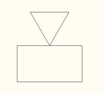
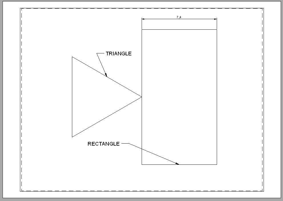
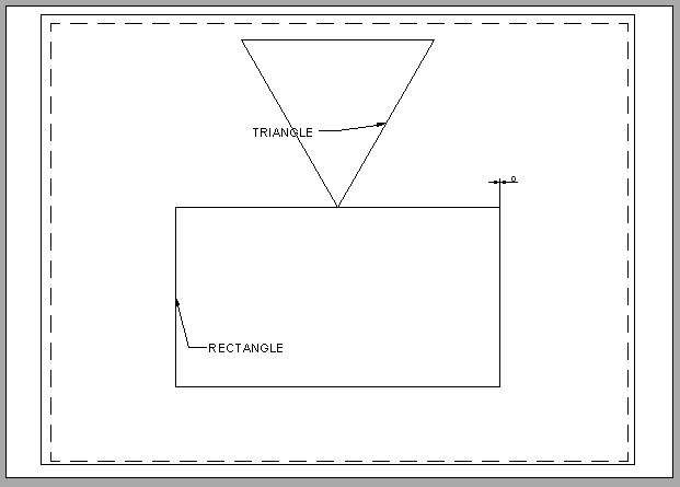
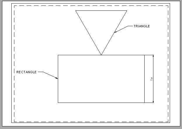
 I have attached copies of the piece part as drawn in the vertical position and another showing the same drawing being selected and then rotated through 90 deg with the bottom LH corner of the border chosen as the base point. As can be seen, the piece part and its dimensions have been successfully rotated but the text fields and the outer border have not.
Looking at Greensand’s two examples, seems to me AutoCAD has rotated the drawing and text correctly in the sense computer graphics understand rotation.
Possibly Greensands is expecting a mix of rotations and moves, that AutoCAD can’t do in one step. I suspect he wants the graphics to rotate, whilst text is moved as a human would move it to look good. If so, that’s a mix of two different transforms, move and rotate, and AutoCAD doesn’t know what the result should be.
What should the result look like? Comparing it to the original would show if the the job can be done simply by rotating the whole drawing, or if the text can be fixed with a second tool, or if the text has to be repositioned manually.
When a 3D-CAD package generates 2D-drawings, it’s usual for the operator to add and position text, balloons, notes and dimensions himself. Necessary because 2D drawings are read by humans, who benefit greatly from careful presentation. The CAM equivalent of a 2D-plan, such as an STL file, makes perfect sense to another machine, but is almost incomprehensible to people. It’s easier to generate G-code than output excellent 2D-drawings, because humans need more help! In future, AI may be able to automate 2D, but at the moment the best solution is to have the computer do the projections, after which a human adds the notes he needs.
Dave
 Martin Connelly.

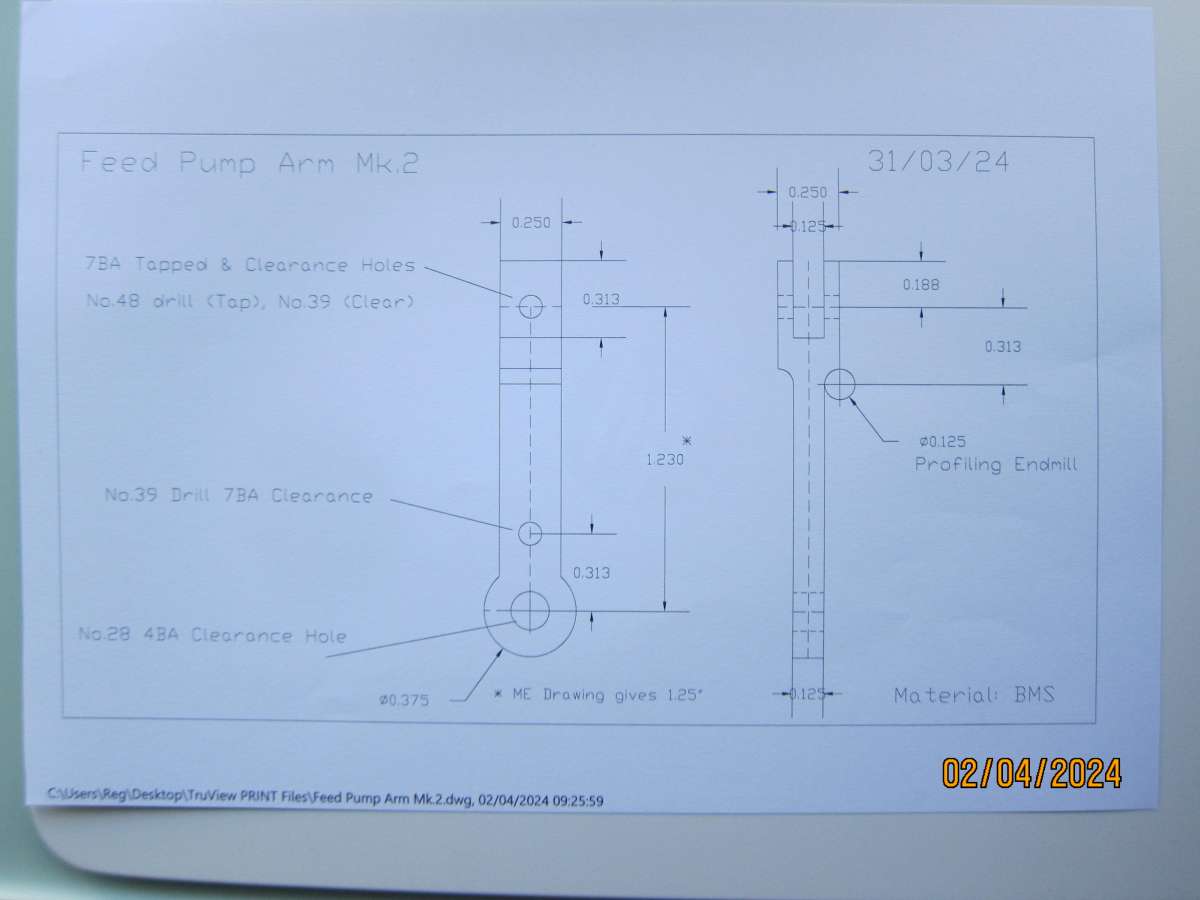
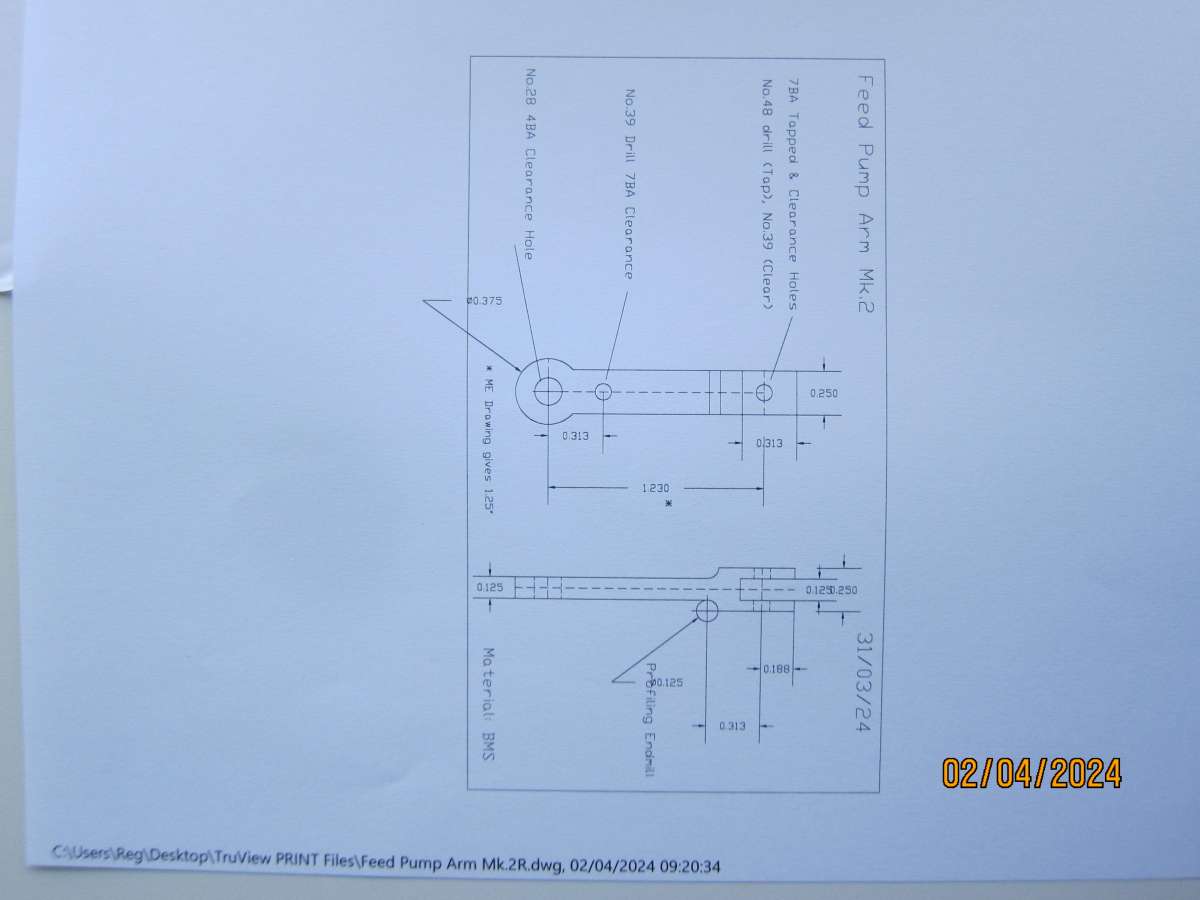 I have attached copies of the piece part as drawn in the vertical position and another showing the same drawing being selected and then rotated through 90 deg with the bottom LH corner of the border chosen as the base point. As can be seen, the piece part and its dimensions have been successfully rotated but the text fields and the outer border have not.