How to machine a flywheel ?

Advert

How to machine a flywheel ?

Home Forums Stationary engines How to machine a flywheel ?

Viewing 25 posts - 26 through 50 (of 123 total)
  • Author
    Posts
  • #157169
    Brian John
    Participant
      @brianjohn93961

      On the castings I have , the flywheel has a gradual slope from the centre of the outside surface down to the sides. I think that this is called the ''crown'' ? Should this be retained when machining the flywheel ? Does it serve any purpose other than for appearance ?

      Advert
      #157174
      roy entwistle
      Participant
        @royentwistle24699

        Brian It's to keep the leather belt on when driving machinery etc

        Roy

        #157175
        JasonB
        Moderator
          @jasonb

          What you have on the raw casting is the draught angle from the pattern which is needed to allow it to be with drawn from the casting sand.

          Depending on the intended engine you can either machine it flat or put a crown on it, either way it will need to be machined to get it smooth and concentric to the bore.

          If the engine has a separate pully to take the drive or its say on a Cameron feed pump etc then the flywheel would have a flat surface and it would be painted. If on the otherhand the flywheel is on a traction engine, portable or some stationary engines then it would need to be crowned as Roy says to keep a drive belt running on the rim. This is actually a radiused surface not a slope.

          J

          #157182
          Brian John
          Participant
            @brianjohn93961

            Is it tricky to machine the crown ? I do not really need it on my flywheels but it might be worth trying.

            #157191
            JasonB
            Moderator
              @jasonb

              I thought that might be the next questionwink 2

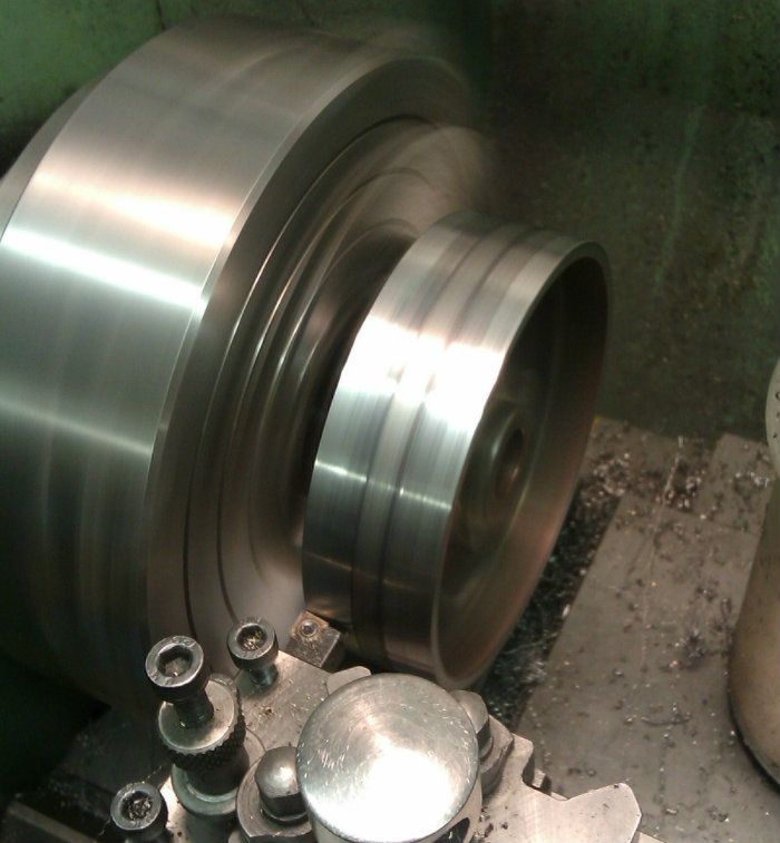
              As shown below from left to right

              1. Turn the sides and face of the flywheel to clean them up

              2. roughly divide the face of teh flywheel into 3 and then by setting teh topslide a degree or two either way turn a shallow taper on teh outer two segments

              3. With care while the lathe is running use a file to blend in the areas where the tapers meet the central section, then finish with Emery cloth backed by a bit of flat wood.

              crowning.jpg

              On larger flywheels and pullies you sometimes have to use 5 facets not three, you should just be able to see the changes in the metal surface where this pully had the 5 facets done

              And the finish after filing and finishing

              #157205
              Ian S C
              Participant
                @iansc

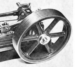
                As well as flat and crowned flywheels, they may be made with rope grooves, like this. This is a Stuart Turner S9 Ian S C

                375339 (640x353).jpg

                #167624
                Brian John
                Participant
                  @brianjohn93961

                  How do you find the exact centre of the hub on the flywheel in order to drill the hole for the axle ?

                  Edited By Brian John on 25/10/2014 05:09:11

                  #167628
                  JasonB
                  Moderator
                    @jasonb

                    Usual way is to set the casting up on the lathe either on a faceplate or using a chuck and adjust its position until yhe inside edge of the rim runs as true as you can get it. Once this is done a facing cut can be taken accross the edge of the hub and then a spotting or centre drill held in the tailstock chuck is used to start the hole, followed buy opening up the hole in stages with drills and finish by boring and or reaming.

                    The outside is machined at the same setting so this ensures that the rim is running true to the bore.

                    J

                    #167642
                    Ennech
                    Participant
                      @ennech

                      There is a section on this page **LINK** showing a regular contributor to the forum machining a flywheel

                      #172857
                      Brian John
                      Participant
                        @brianjohn93961

                        Should flywheels be painted first prior to machining ? I have read a few articles where the machinist did it this way as it saves having to mask off areas you do not want painted . It sounds like an excellent idea but are there any disadvantages to this method ?

                        Edited By Brian John on 18/12/2014 03:52:59

                        #172859
                        JasonB
                        Moderator
                          @jasonb

                          As you often need to hold the flywheel by the spokes or inside the rim you run the risk of damaging the paint.

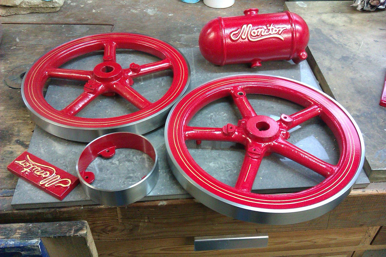
                          I tend to just mask the outside face of the rim and the bore to keep the worst of the paint of any bare metal then when its dry mount the flywheel in a mandrel and just take any paint of the rim with some abrasive ( cover the lathe bed with a board)

                          Finish turned flywheels masked for painting

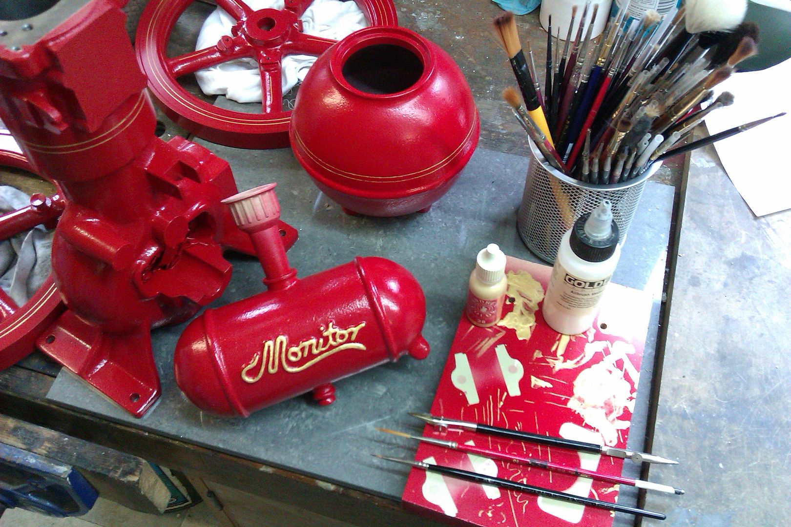
                          Add the pinstriping

                          Cleaned up to 400g which gives the satin finish I prefer to a blingy polished one

                          Edited By JasonB on 18/12/2014 07:34:42

                          #172893
                          Brian John
                          Participant
                            @brianjohn93961

                            Nicely done : how did you do the pinstriping ?

                            #172895
                            JasonB
                            Moderator
                              @jasonb

                              Mostly with just a ruling pen held against a suitable guide, in the case case of teh one above it was a french curve.

                              For rings around the flywheel I use the same ruling pen but steady may hand on the lathe toolpost as I rotate the flywheel by hand

                              You will probably have to thin the paint a little, the one above is Humbrol so just used their thinners. The one below was a gold acrylic so used some airbrush medium that I had.

                              #184904
                              Brian John
                              Participant
                                @brianjohn93961

                                When drilling the hole for the axle, should I drill a small hole first and get progressively larger ? Or just go straight to the 6.2mm drill bit and later finish with a 1/4 inch reamer ?

                                #184907
                                JasonB
                                Moderator
                                  @jasonb

                                  The 6.2mm drill could cut oversize and as you will be using a small machine I would say

                                  Face end of hub so drill won't wander

                                  Spot drill (centre drill if you wish)

                                  Drill 5mm, preferably a stub drill

                                  Drill 6.2

                                  Ream

                                  Given the choice and a suitable boring bar I would drill about 5.5mm and then bore it out to a nice fit on the shaft as the reamer may give a fractionally larger hole than the actual size of your shaft.

                                  Edited By JasonB on 30/03/2015 07:59:29

                                  #185079
                                  duncan webster 1
                                  Participant
                                    @duncanwebster1

                                    I just gripped it in the 4 jaw using external jaws, face, bore for crank. then bore a register into the rim and take a skim as far as you can on OD. Turn round and grip using register, clock to skimmed OD, turn OD and face other side. trying to do it off a mandrel is hard work, chatter and ringing as the rim is not well supported

                                    #198685
                                    Brian John
                                    Participant
                                      @brianjohn93961

                                      How about this method that I have read on the internet which does not use a face plate but the flywheel must be small enough to be held fully within the jaws of the lathe chuck :

                                      1. Hold flywheel ( 3.5 or 4 inch) in the lathe chuck by the outer rim ( They recommend a 4 jaw chuck but I am not sure why ?)

                                      2. face the hub and the rim on one side.

                                      3. Spot drill with 6mm spot drill bit

                                      4. ream out to correct size. (I have been thinking of using 6mm axles instead of 1/4 inch)

                                      5. take flywheel out of chuck and fit mandrel

                                      5. place mandrel in lathe and face the other side

                                      6. finish by facing the main outer surface of the flywheel

                                      I have been looking at mandrels from Arceuro : straight shank expanding mandrels (5.5mm to 7mm)

                                      **LINK**

                                      #198689
                                      JasonB
                                      Moderator
                                        @jasonb

                                        It works for small flywheels, larger can start to chatter but I don't think I would want to do a 4" flywheel on a 6mm mandrel, nice as the ARC ones are you could make your own which would be a lot shorter and therefore less prone to flex/vibration.

                                        4-jaw is because casting will not be perfectly round so needs adjusting to turn as true as possible hence the adjustment of the jaws

                                        #198695
                                        Steve Withnell
                                        Participant
                                          @stevewithnell34426

                                          Before you ream to size, I'd try a test on some similar material, the last one I did, I wasn't 100% happy with the fit, it felt a little loose so tend to bore to a fit now, but that's with 3/8th axles, might be less of an issue with 6mm.

                                          MIght have been the reamer or my reaming technique though! One thing to check for is that you drill to the correct size before reaming – the reamer mustn't have too much work to do or too little.

                                          I can't see any issue with using 6mm instead of 1/4inch. The thing I like about building these small engines is that you can vary things to suit and try out your ideas in the build. There tends to be only a few critical dimensions to watch for.

                                          Steve

                                          #198719
                                          Neil Wyatt
                                          Moderator
                                            @neilwyatt

                                            Trouble with reamers is the usual ones we get are H6 and they are a wee bit too loose to ensure something as wide in relation to its thickness as a flywheel is accurately aligned.

                                            Worst is in cast iron, where the freshly machined part is a snug fit and two days latter its become a tad loose as the dust shakes out

                                            Neil

                                            #198725
                                            Brian John
                                            Participant
                                              @brianjohn93961

                                              Jason : I do not have a slit saw.

                                              Steve : I would not use a reamer unless I had to.

                                              #198729
                                              JasonB
                                              Moderator
                                                @jasonb

                                                Brian you don't need a slitting saw, your junior hacksaw will do the job, infact you can make one without a saw.

                                                #198730
                                                Michael Gilligan
                                                Participant
                                                  @michaelgilligan61133
                                                  Posted by Brian John on 01/08/2015 11:11:38:

                                                  I would not use a reamer unless I had to.

                                                  .

                                                  ?

                                                  Are you planning to just drill it then?

                                                  … or will you be boring 6mm on your new lathe?

                                                  MichaelG.

                                                  .

                                                  P.S. … a 'D-bit' is probably the best tool to use.


                                                  Edited By Michael Gilligan on 01/08/2015 12:13:56

                                                  #198732
                                                  KWIL
                                                  Participant
                                                    @kwil

                                                    First pass with a pencil, can be used to show where the maximum runouts are. Just move towards the part in question, slowly until a single (or more) touches show.

                                                    #198751
                                                    Dinosaur Engineer
                                                    Participant
                                                      @dinosaurengineer
                                                      Posted by Neil Wyatt on 01/08/2015 10:33:53:

                                                      Trouble with reamers is the usual ones we get are H6 and they are a wee bit too loose to ensure something as wide in relation to its thickness as a flywheel is accurately aligned.

                                                      Worst is in cast iron, where the freshly machined part is a snug fit and two days latter its become a tad loose as the dust shakes out

                                                      Neil

                                                      The normal "cheap" reamers are H7 . The tighter tolerance more expensive H6 grade are not stocked by the some of the modeller's stockists. It is possible to stone a reamer to cut a little smaller.

                                                    Viewing 25 posts - 26 through 50 (of 123 total)
                                                    • Please log in to reply to this topic. Registering is free and easy using the links on the menu at the top of this page.

                                                    Advert

                                                    Latest Replies

                                                    Home Forums Stationary engines Topics

                                                    Viewing 25 topics - 1 through 25 (of 25 total)
                                                    Viewing 25 topics - 1 through 25 (of 25 total)

                                                    View full reply list.

                                                    Advert

                                                    Newsletter Sign-up